ECE 301: MATLAB and VHDL Assignment - Signal Processing and Filtering
VerifiedAdded on 2023/04/21
|10
|1010
|50
Homework Assignment
AI Summary
This assignment solution demonstrates the application of MATLAB and VHDL in digital signal processing and circuit design. The assignment involves generating and analyzing a signal composed of multiple sinusoidal components with added noise, designing a bandpass filter using MATLAB's FDAtool to recover the original signal, and implementing a full adder in Verilog. The solution includes MATLAB code for filter design, analysis, and plotting, along with Verilog code for a half adder, a full adder, and a 5-bit full adder. The document also provides figures illustrating the filter's performance and a bibliography of relevant references.

MATLAB AND VHDL 1
MATLAB AND VHDL
By Name
Course
Instructor
Institution
Location
Date
MATLAB AND VHDL
By Name
Course
Instructor
Institution
Location
Date
Paraphrase This Document
Need a fresh take? Get an instant paraphrase of this document with our AI Paraphraser
MATLAB AND VHDL 2
QUESTION 1
Part a
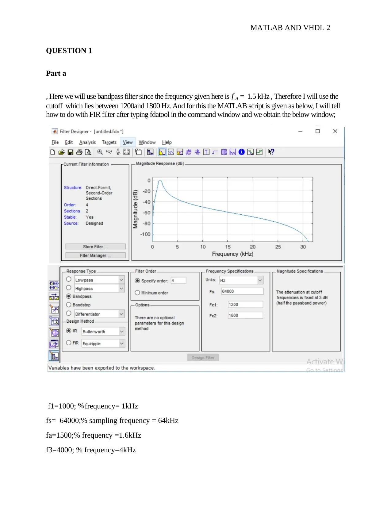
, Here we will use bandpass filter since the frequency given here is f A = 1.5 kHz , Therefore I will use the
cutoff which lies between 1200and 1800 Hz. And for this the MATLAB script is given as below, I will tell
how to do with FIR filter after typing fdatool in the command window and we obtain the below window;
f1=1000; %frequency= 1kHz
fs= 64000;% sampling frequency = 64kHz
fa=1500;% frequency =1.6kHz
f3=4000; % frequency=4kHz
MATLAB AND VHDL 3
t=0:1/fs:5/f1;
x=0.1.*sin(2*pi*f1*t)+1*sin(2*pi*fa.*t)+0.1*sin(2*f3.*t)+0.05.*randn(1, length(t));% adding
three signal with noise %% filter design from FDATOOL ( command:fdatool)
% Design a suitable bandpass filter having cutoff frequency 1200Hz and 1800Hz
% Hz sample frequency of 64000Hz with an order of 10 (Butterworth Model)
% type fdatool in command window,
Part b
[b a ] =sos2tf(SOS,G);
y= filter (b,a,x);
Plot(y)
%%%%%%%%%%%%%%%%%%%%%%%%%%%%%%%%%%%%%%%%%%%%%
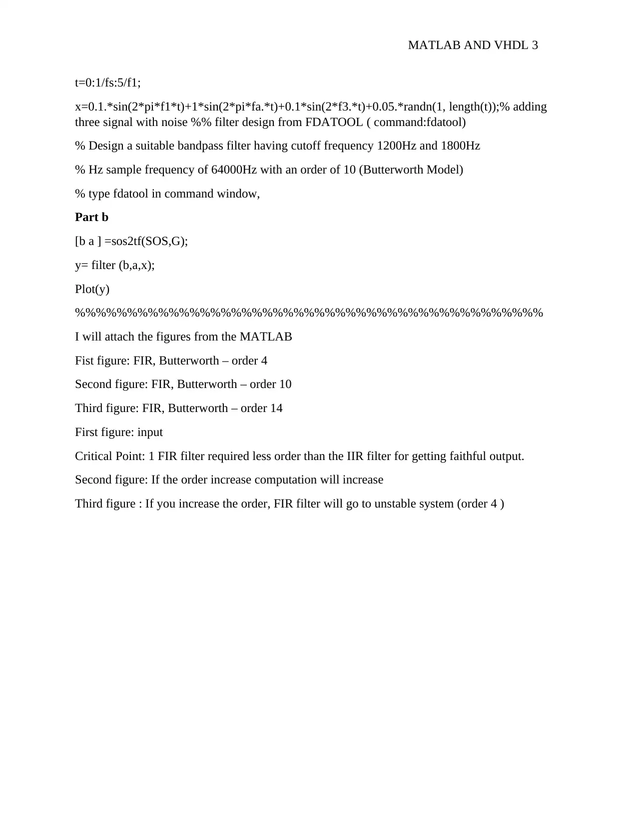
I will attach the figures from the MATLAB
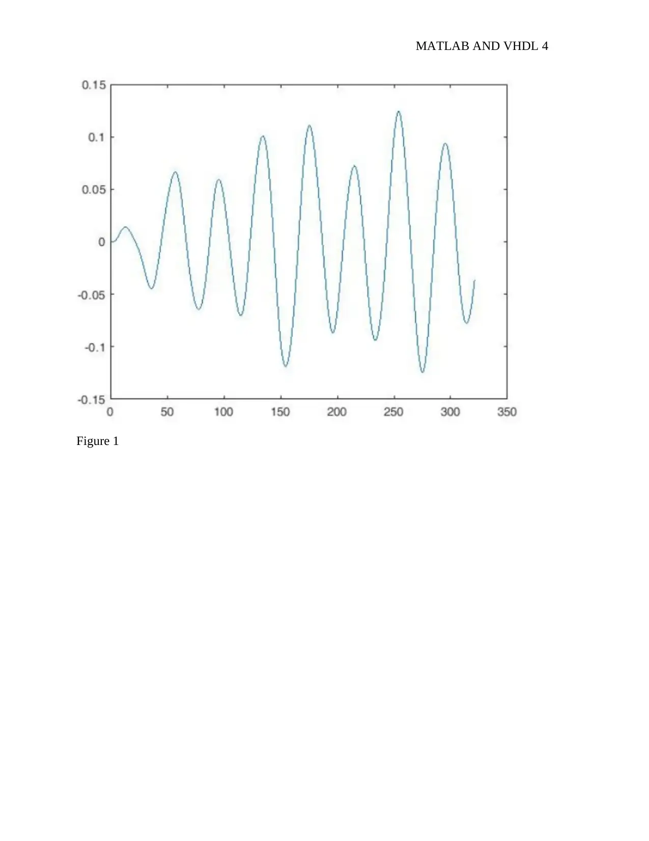
Fist figure: FIR, Butterworth – order 4
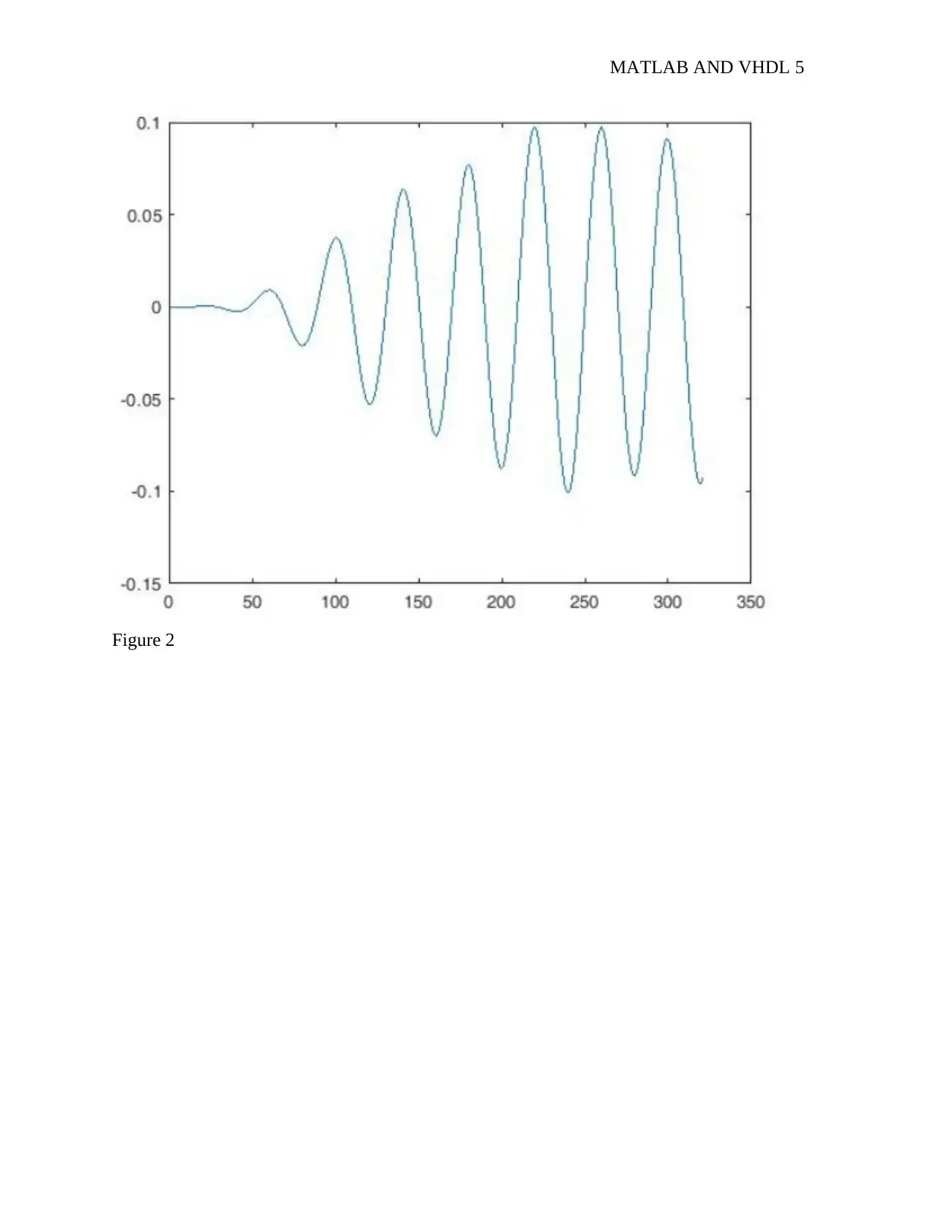
Second figure: FIR, Butterworth – order 10
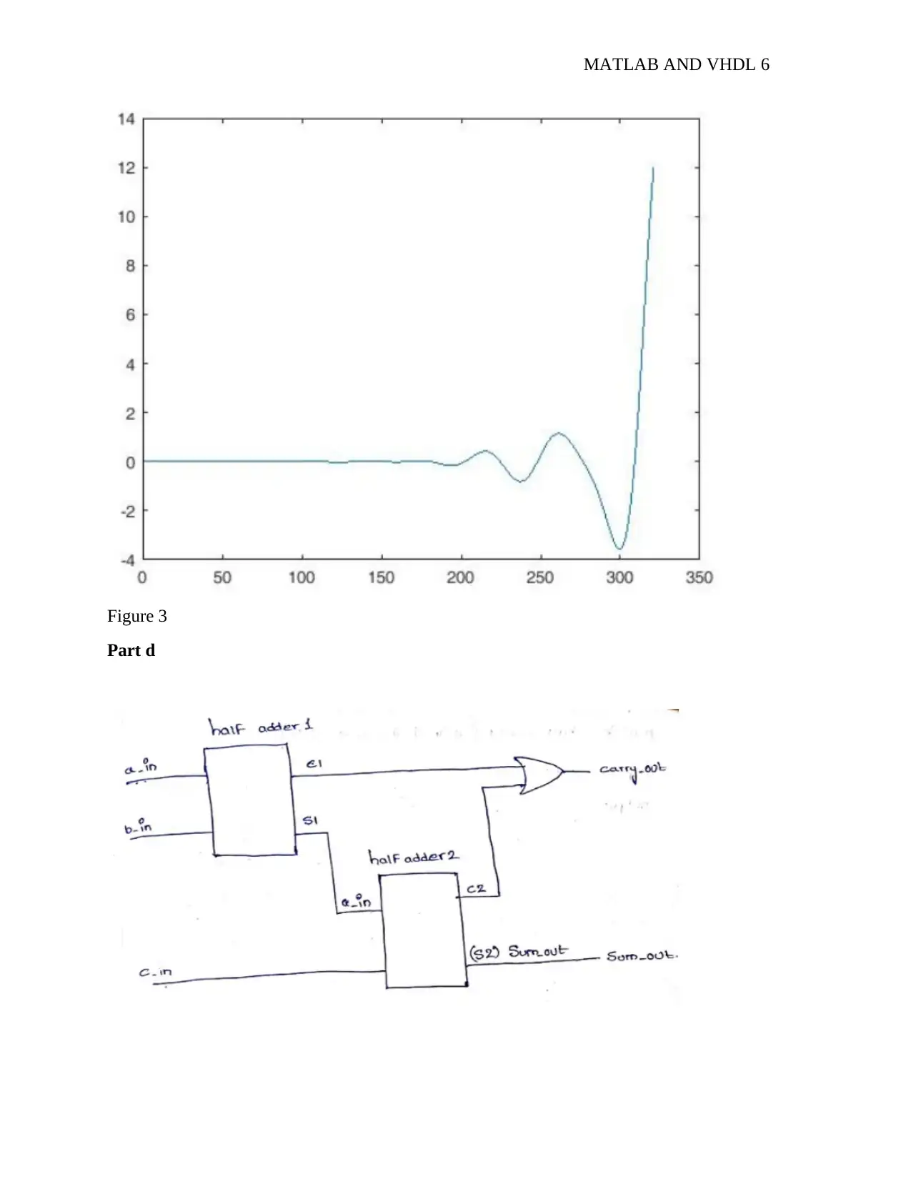
Third figure: FIR, Butterworth – order 14
First figure: input
Critical Point: 1 FIR filter required less order than the IIR filter for getting faithful output.
Second figure: If the order increase computation will increase
Third figure : If you increase the order, FIR filter will go to unstable system (order 4 )
⊘ This is a preview!⊘
Do you want full access?
Subscribe today to unlock all pages.

Trusted by 1+ million students worldwide
MATLAB AND VHDL 4
Figure 1
Figure 1
Paraphrase This Document
Need a fresh take? Get an instant paraphrase of this document with our AI Paraphraser
MATLAB AND VHDL 5
Figure 2
Figure 2
MATLAB AND VHDL 6
Figure 3
Part d
Figure 3
Part d
⊘ This is a preview!⊘
Do you want full access?
Subscribe today to unlock all pages.

Trusted by 1+ million students worldwide
MATLAB AND VHDL 7
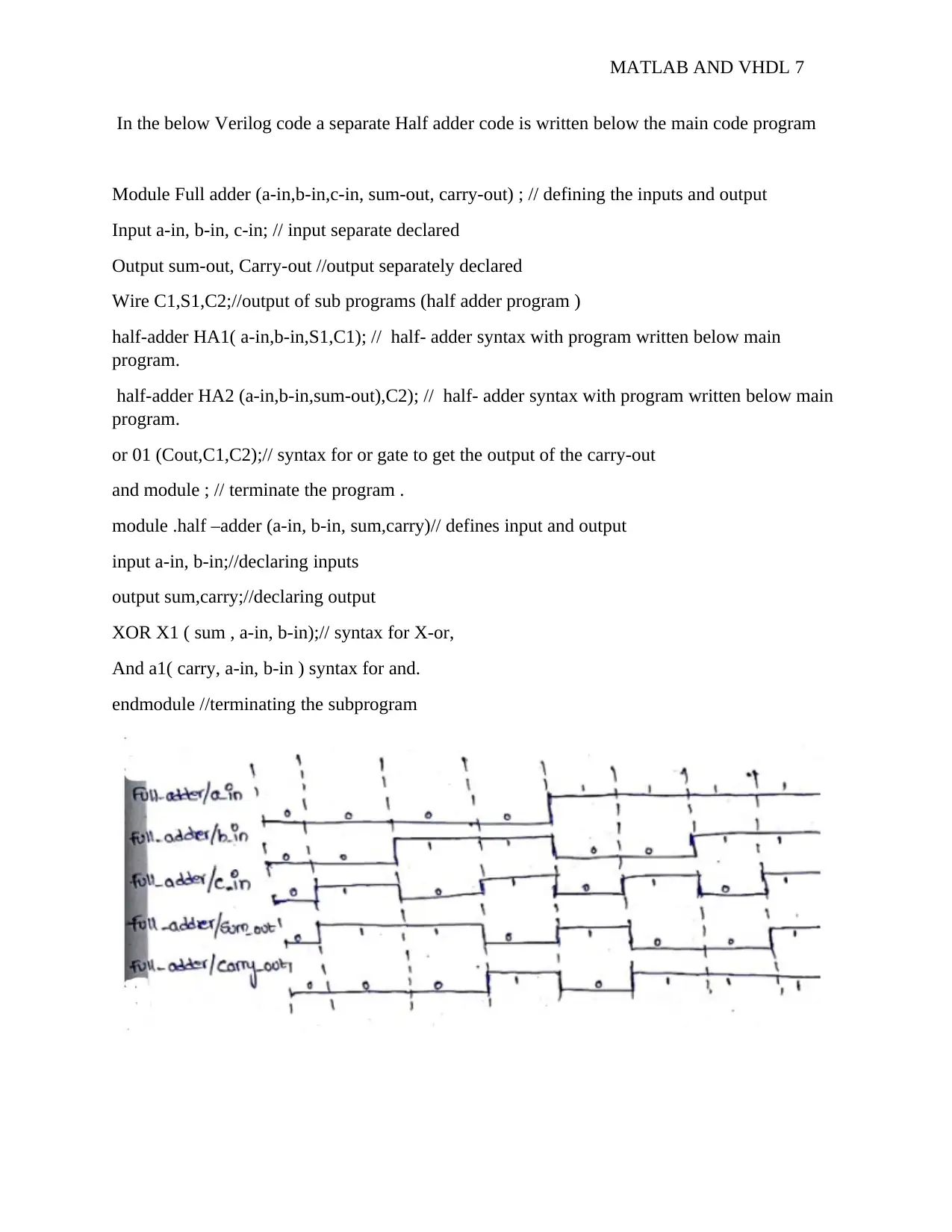
In the below Verilog code a separate Half adder code is written below the main code program
Module Full adder (a-in,b-in,c-in, sum-out, carry-out) ; // defining the inputs and output
Input a-in, b-in, c-in; // input separate declared
Output sum-out, Carry-out //output separately declared
Wire C1,S1,C2;//output of sub programs (half adder program )
half-adder HA1( a-in,b-in,S1,C1); // half- adder syntax with program written below main
program.
half-adder HA2 (a-in,b-in,sum-out),C2); // half- adder syntax with program written below main
program.
or 01 (Cout,C1,C2);// syntax for or gate to get the output of the carry-out
and module ; // terminate the program .
module .half –adder (a-in, b-in, sum,carry)// defines input and output
input a-in, b-in;//declaring inputs
output sum,carry;//declaring output
XOR X1 ( sum , a-in, b-in);// syntax for X-or,
And a1( carry, a-in, b-in ) syntax for and.
endmodule //terminating the subprogram
Paraphrase This Document
Need a fresh take? Get an instant paraphrase of this document with our AI Paraphraser
MATLAB AND VHDL 8
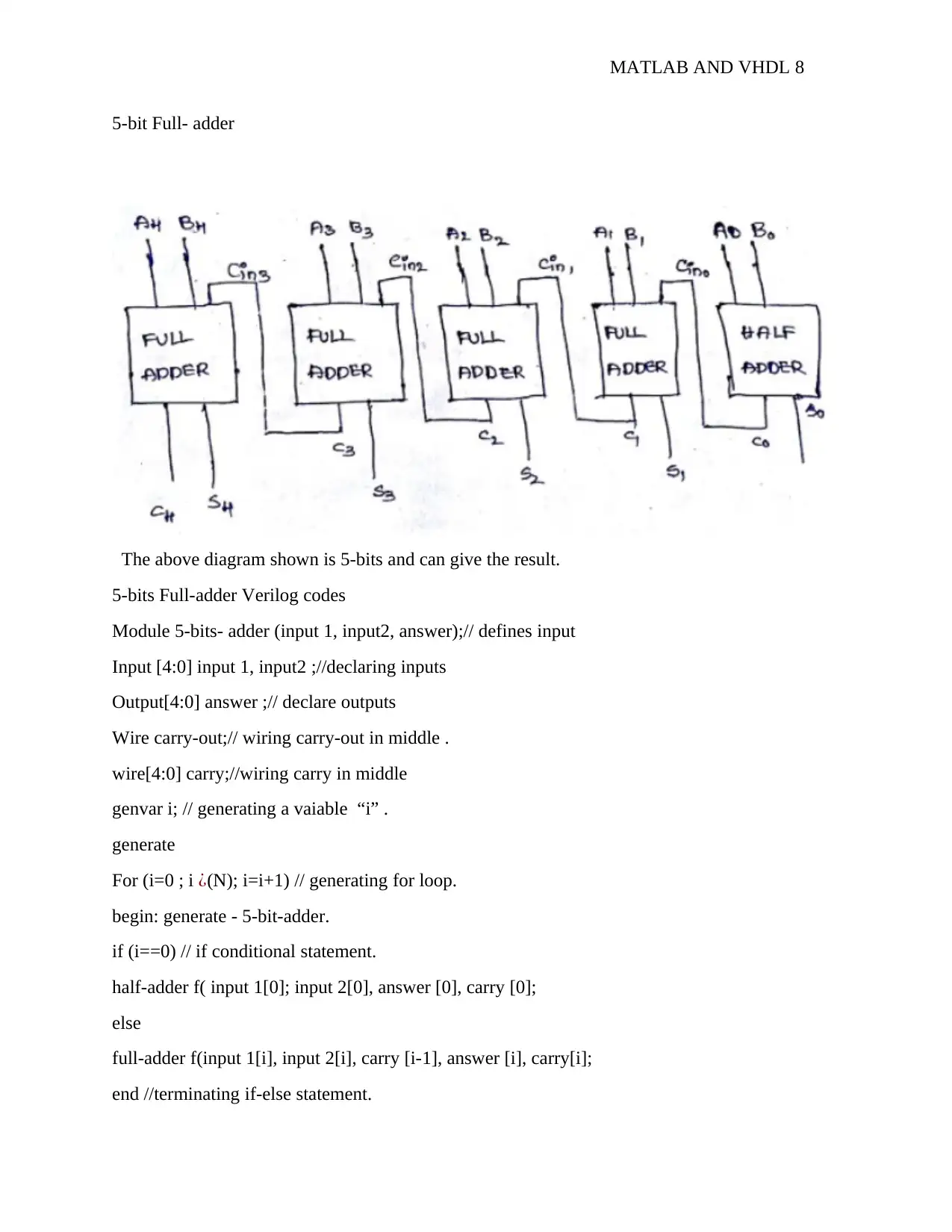
5-bit Full- adder
The above diagram shown is 5-bits and can give the result.
5-bits Full-adder Verilog codes
Module 5-bits- adder (input 1, input2, answer);// defines input
Input [4:0] input 1, input2 ;//declaring inputs
Output[4:0] answer ;// declare outputs
Wire carry-out;// wiring carry-out in middle .
wire[4:0] carry;//wiring carry in middle
genvar i; // generating a vaiable “i” .
generate
For (i=0 ; i ¿(N); i=i+1) // generating for loop.
begin: generate - 5-bit-adder.
if (i==0) // if conditional statement.
half-adder f( input 1[0]; input 2[0], answer [0], carry [0];
else
full-adder f(input 1[i], input 2[i], carry [i-1], answer [i], carry[i];
end //terminating if-else statement.
MATLAB AND VHDL 9
assign carry-out = carry[4]; // assigning carry- out is equal to carry .
end generate // terminating for loop.
end module // terminating main program
module half-adder(x,y,s,c); // define input &outputs
input x,y; // declaring inputs
outputs s,c;//declaring outputs
assign s= x*y ; // assigning sum = X+Y
assign c=xε1y; // assigning carry =x.y
endmodule// terminating sub- programing.
Module full-adder (x,y,c-in,s,c-out); //declare input and output
Input x,y,c-in; define inputs.
Output s,cout ; // define outputs
Assign s=(x*y) ,c-in ; // assigning s=(x+y)+C-ins
Assign C-out =(y&C-in ) ( x &y ) ( x&C-in); // assigning carry=y.cin +x.y+c.c-in .
⊘ This is a preview!⊘
Do you want full access?
Subscribe today to unlock all pages.

Trusted by 1+ million students worldwide

MATLAB AND VHDL 10
Bibliography
Furber, S., 2013. Principles of Asynchronous Circuit Design: A Systems Perspective. 4th ed.
Chicago: Springer Science & Business Media.
Pedroni, V. A., 2014. Circuit Design with VHDL. 2nd ed. Hull: MIT Press.
Bibliography
Furber, S., 2013. Principles of Asynchronous Circuit Design: A Systems Perspective. 4th ed.
Chicago: Springer Science & Business Media.
Pedroni, V. A., 2014. Circuit Design with VHDL. 2nd ed. Hull: MIT Press.
1 out of 10
Your All-in-One AI-Powered Toolkit for Academic Success.
+13062052269
info@desklib.com
Available 24*7 on WhatsApp / Email
![[object Object]](/_next/static/media/star-bottom.7253800d.svg)
Unlock your academic potential
Copyright © 2020–2026 A2Z Services. All Rights Reserved. Developed and managed by ZUCOL.