Industrial Systems (Unit 45) Assignment 3: Measuring Systems Report
VerifiedAdded on 2021/02/22
|9
|1741
|441
Report
AI Summary
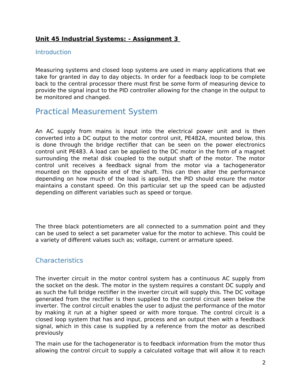
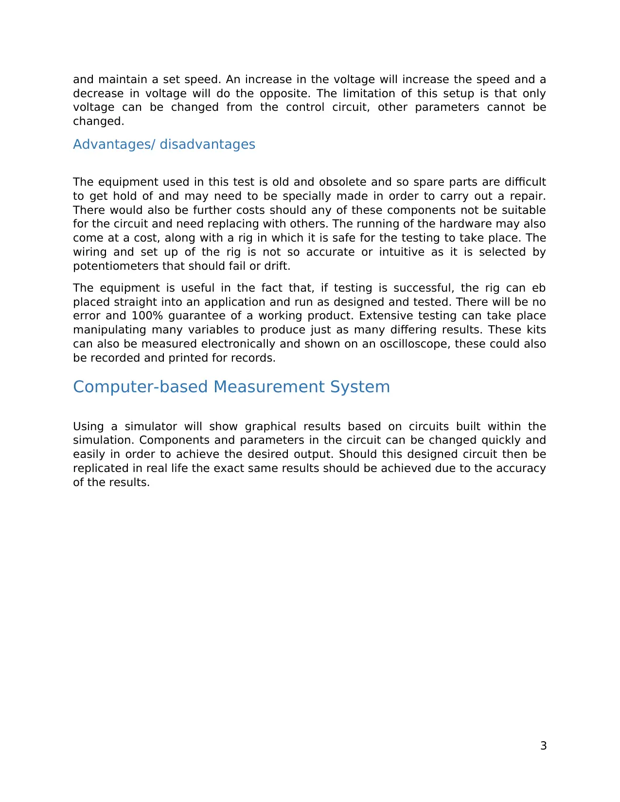
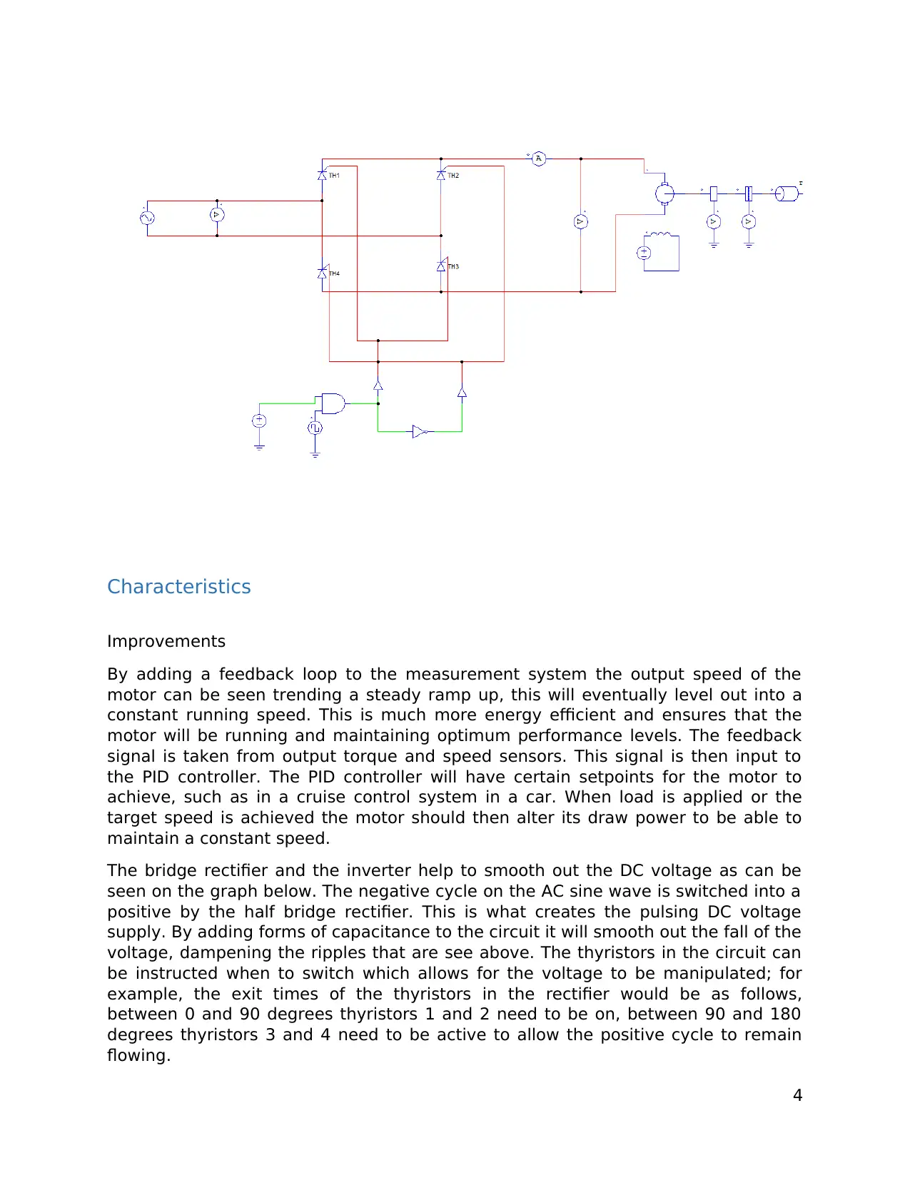
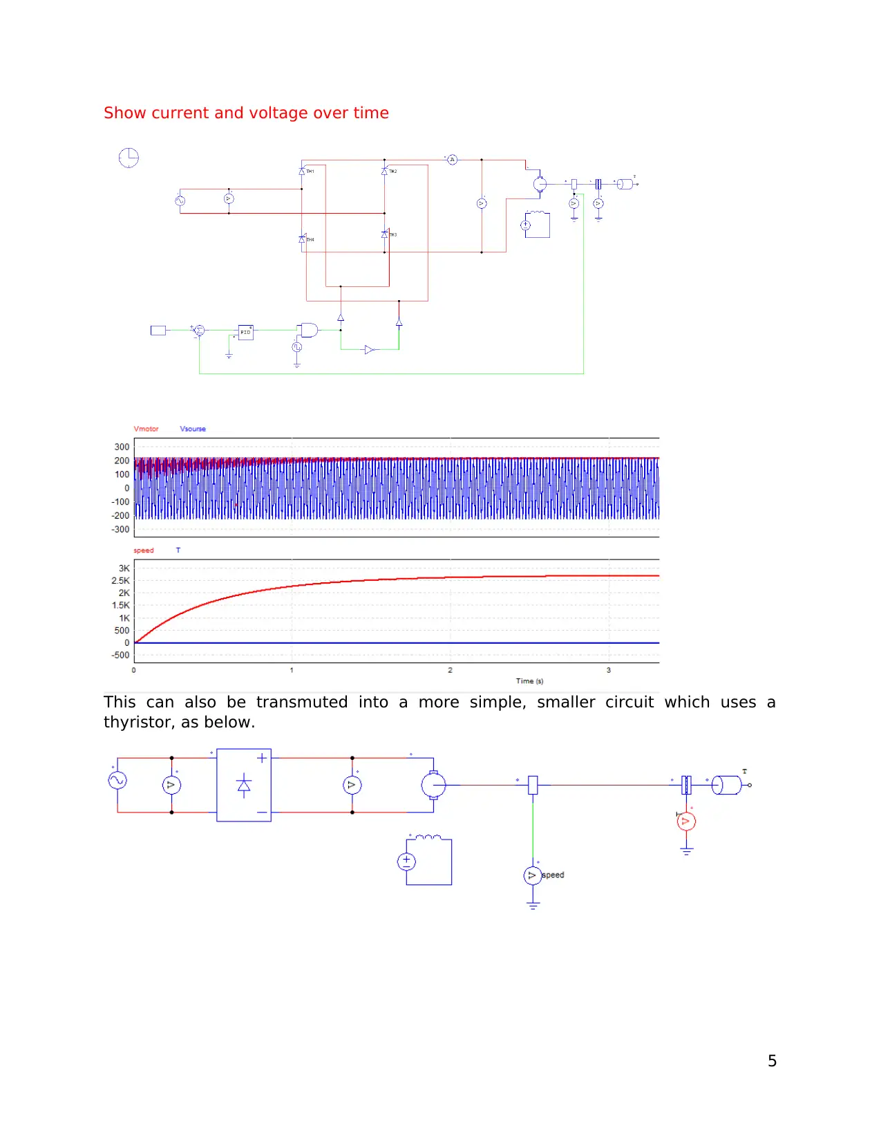
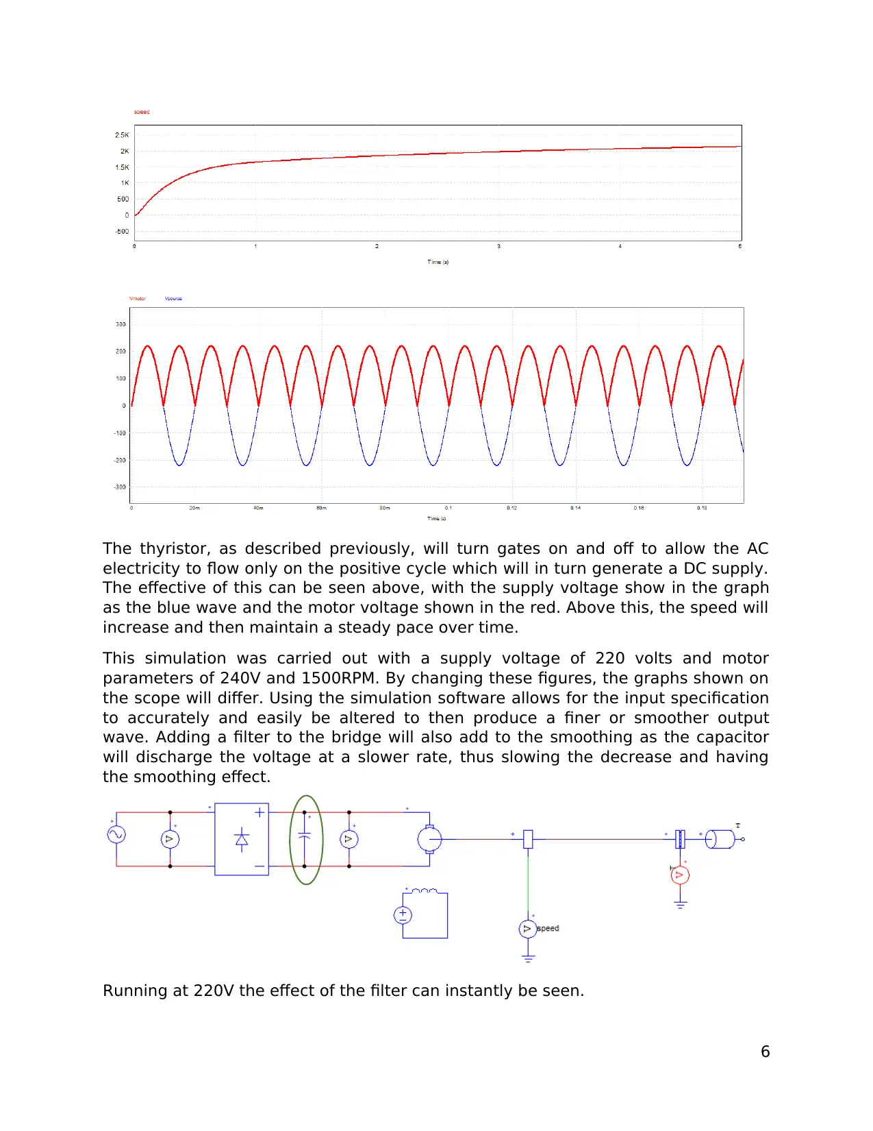
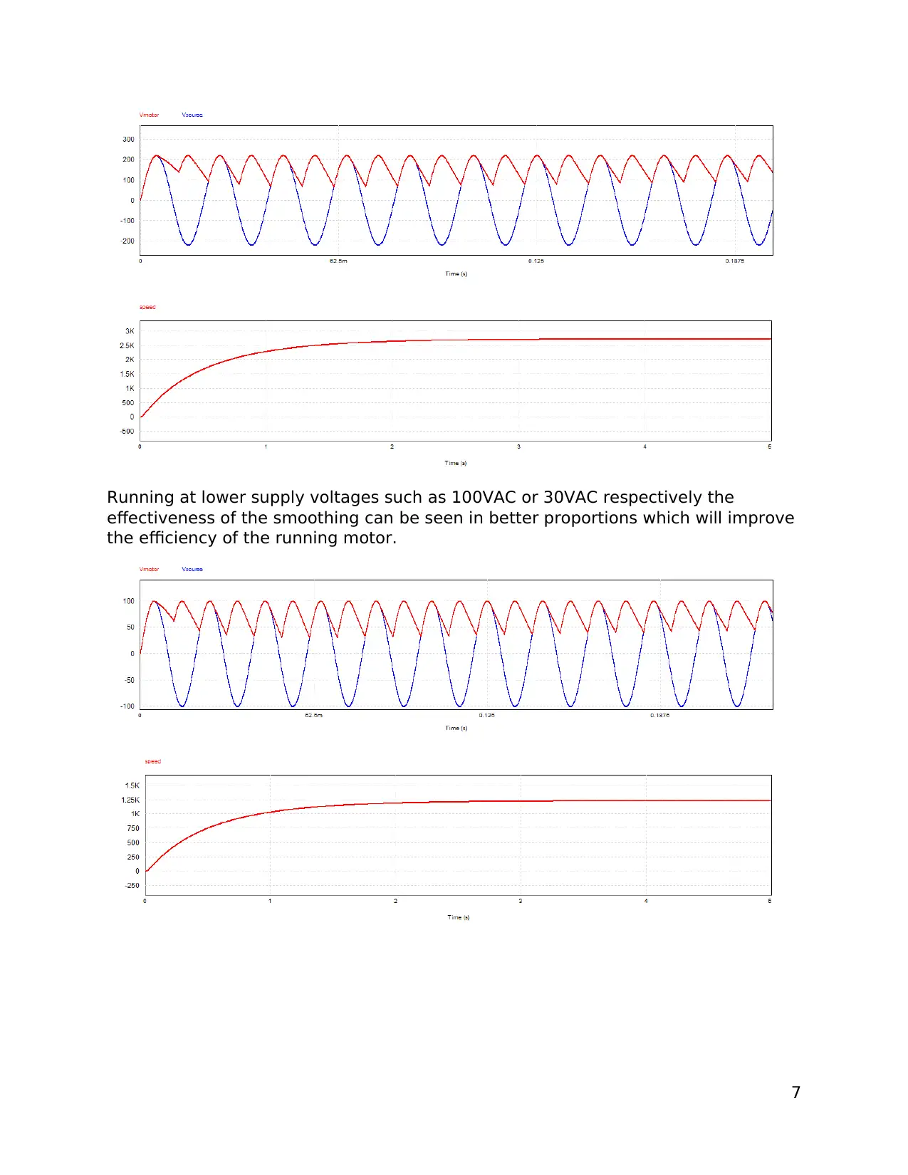
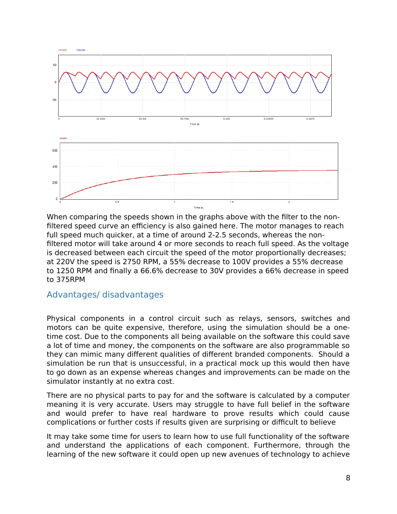
This report examines industrial measuring systems and closed-loop systems, crucial components in many applications. It delves into practical measurement systems, detailing an AC-to-DC conversion setup with a motor control unit, a tachogenerator for feedback, and the role of a PID controller in maintaining constant speed. The report also explores the characteristics, advantages, and disadvantages of this physical setup, including the obsolescence of the equipment and the limitations in parameter adjustments. Furthermore, it investigates computer-based measurement systems using simulation software, highlighting the benefits of quickly changing components and parameters to achieve desired outputs. The report discusses improvements through feedback loops, the role of bridge rectifiers and inverters in smoothing DC voltage, and the use of thyristors for voltage manipulation. It also provides comparisons between filtered and non-filtered circuits, showcasing the advantages of simulation in terms of cost-effectiveness, accuracy, and the ability to optimize system performance before implementation. The report concludes with an evaluation of the accuracy of measurement systems with feedback loops and the benefits of using simulation software in designing and optimizing industrial circuits.


1 out of 9
Related Documents


Your All-in-One AI-Powered Toolkit for Academic Success.
+13062052269
info@desklib.com
Available 24*7 on WhatsApp / Email
![[object Object]](/_next/static/media/star-bottom.7253800d.svg)
Copyright © 2020–2026 A2Z Services. All Rights Reserved. Developed and managed by ZUCOL.