MEC 301: Manufacturing Processes Homework Solution - Abu Dhabi Uni

Verified

Added on  2023/06/13

|3
|1002
|54
Homework Assignment
AI Summary
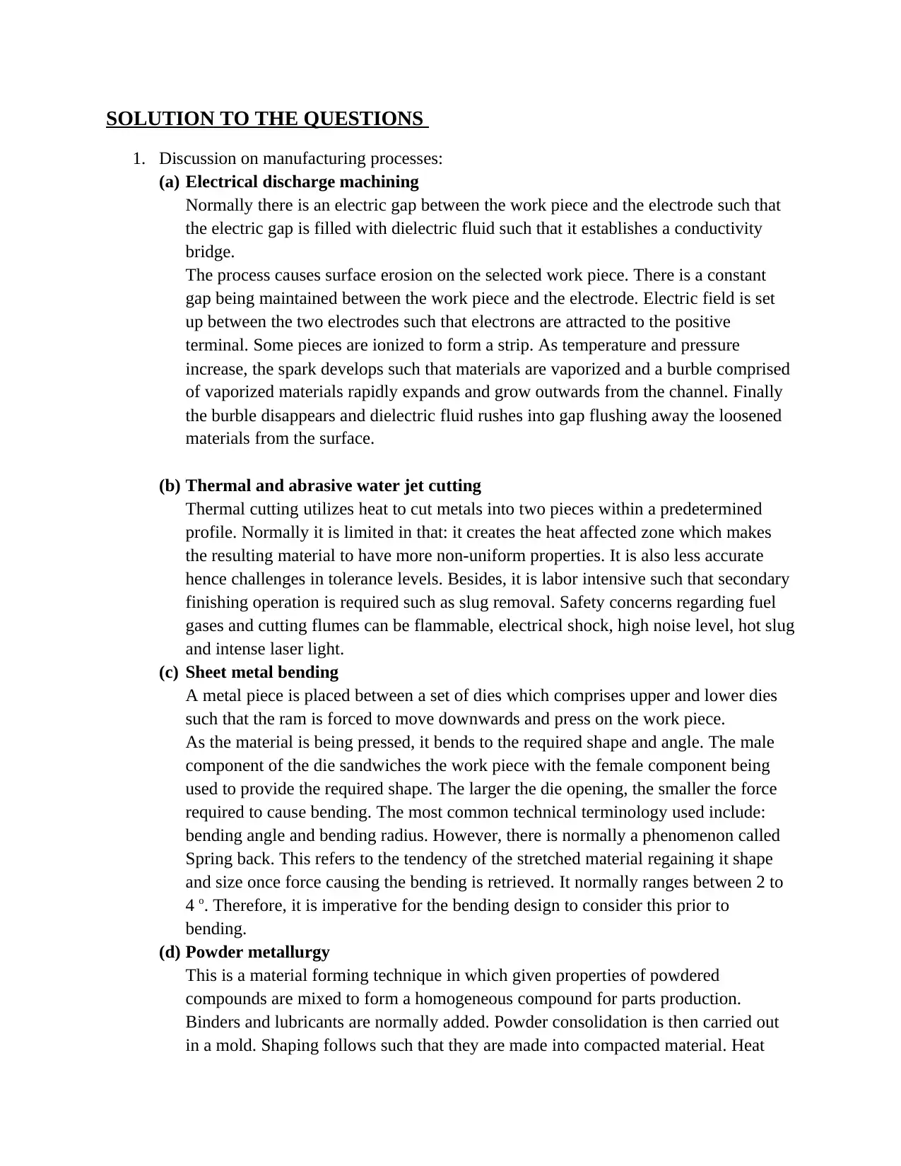
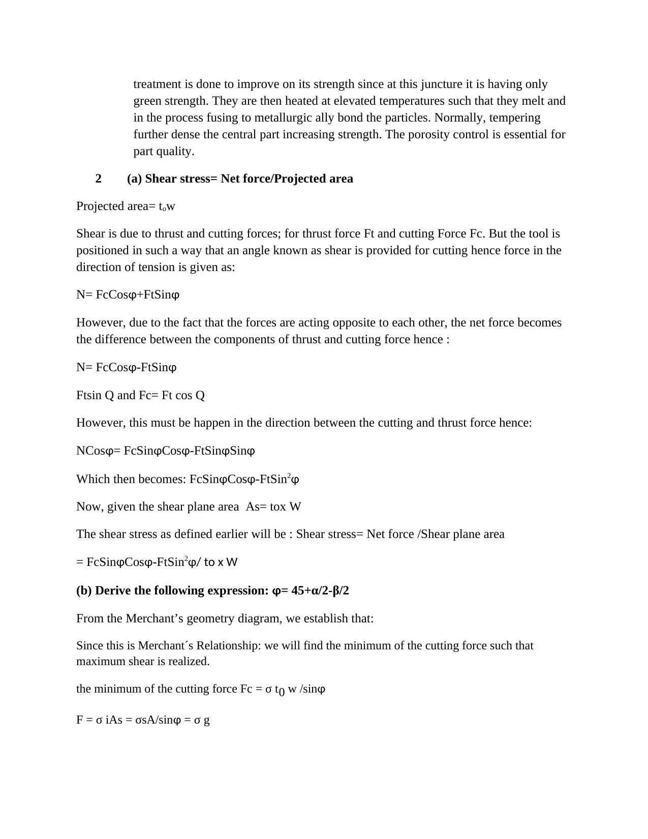
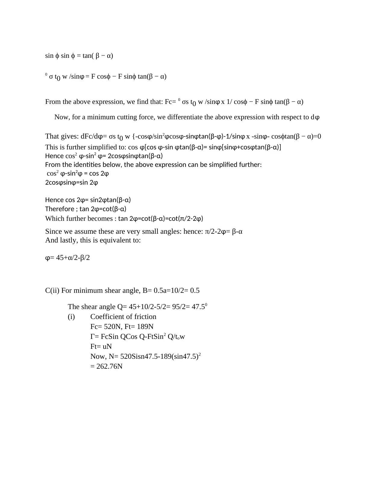
This document presents a solution to a manufacturing processes homework assignment, covering topics such as electrical discharge machining (EDM), thermal and abrasive water jet cutting, sheet metal bending, and powder metallurgy. It includes a discussion of each process, addressing principles, advantages, and limitations. The solution also verifies an expression for shear stress in orthogonal cutting and derives a relationship between shear angle, friction angle, and rake angle. Furthermore, it details the process of creating a toy or keychain using injection molding with Autodesk Moldflow, including design creation, simulation, parameter settings, and result analysis. This comprehensive solution provides valuable insights into various manufacturing techniques and their practical applications.
Document Page
SOLUTION TO THE QUESTIONS
1. Discussion on manufacturing processes:
(a) Electrical discharge machining
Normally there is an electric gap between the work piece and the electrode such that
the electric gap is filled with dielectric fluid such that it establishes a conductivity
bridge.
The process causes surface erosion on the selected work piece. There is a constant
gap being maintained between the work piece and the electrode. Electric field is set
up between the two electrodes such that electrons are attracted to the positive
terminal. Some pieces are ionized to form a strip. As temperature and pressure
increase, the spark develops such that materials are vaporized and a burble comprised
of vaporized materials rapidly expands and grow outwards from the channel. Finally
the burble disappears and dielectric fluid rushes into gap flushing away the loosened
materials from the surface.
(b) Thermal and abrasive water jet cutting
Thermal cutting utilizes heat to cut metals into two pieces within a predetermined
profile. Normally it is limited in that: it creates the heat affected zone which makes
the resulting material to have more non-uniform properties. It is also less accurate
hence challenges in tolerance levels. Besides, it is labor intensive such that secondary
finishing operation is required such as slug removal. Safety concerns regarding fuel
gases and cutting flumes can be flammable, electrical shock, high noise level, hot slug
and intense laser light.
(c) Sheet metal bending
A metal piece is placed between a set of dies which comprises upper and lower dies
such that the ram is forced to move downwards and press on the work piece.
As the material is being pressed, it bends to the required shape and angle. The male
component of the die sandwiches the work piece with the female component being
used to provide the required shape. The larger the die opening, the smaller the force
required to cause bending. The most common technical terminology used include:
bending angle and bending radius. However, there is normally a phenomenon called
Spring back. This refers to the tendency of the stretched material regaining it shape
and size once force causing the bending is retrieved. It normally ranges between 2 to
4 o. Therefore, it is imperative for the bending design to consider this prior to
bending.
(d) Powder metallurgy
This is a material forming technique in which given properties of powdered
compounds are mixed to form a homogeneous compound for parts production.
Binders and lubricants are normally added. Powder consolidation is then carried out
in a mold. Shaping follows such that they are made into compacted material. Heat
tabler-icon-diamond-filled.svg

Secure Best Marks with AI Grader

Need help grading? Try our AI Grader for instant feedback on your assignments.
Document Page
treatment is done to improve on its strength since at this juncture it is having only
green strength. They are then heated at elevated temperatures such that they melt and
in the process fusing to metallurgic ally bond the particles. Normally, tempering
further dense the central part increasing strength. The porosity control is essential for
part quality.
2 (a) Shear stress= Net force/Projected area
Projected area= tow
Shear is due to thrust and cutting forces; for thrust force Ft and cutting Force Fc. But the tool is
positioned in such a way that an angle known as shear is provided for cutting hence force in the
direction of tension is given as:
N= FcCosɸ+FtSinɸ
However, due to the fact that the forces are acting opposite to each other, the net force becomes
the difference between the components of thrust and cutting force hence :
N= FcCosɸ-FtSinɸ
Ftsin Q and Fc= Ft cos Q
However, this must be happen in the direction between the cutting and thrust force hence:
NCosɸ= FcSinɸCosɸ-FtSinɸSinɸ
Which then becomes: FcSinɸCosɸ-FtSin2ɸ
Now, given the shear plane area As= tox W
The shear stress as defined earlier will be : Shear stress= Net force /Shear plane area
= FcSinɸCosɸ-FtSin2ɸ/ to x W
(b) Derive the following expression: ɸ= 45+α/2-β/2
From the Merchant’s geometry diagram, we establish that:
Since this is Merchant´s Relationship: we will find the minimum of the cutting force such that
maximum shear is realized.
the minimum of the cutting force Fc = σ t0 w /sinɸ
F = σ iAs = σsA/sinɸ = σ g
Document Page
sin ϕ sin ϕ = tan( β − α)
0 σ t0 w /sinɸ = F cosϕ − F sinϕ tan(β − α)
From the above expression, we find that: Fc= 0 σs t0 w /sinɸ x 1/ cosϕ − F sinϕ tan(β − α)
Now, for a minimum cutting force, we differentiate the above expression with respect to dɸ
That gives: dFc/dɸ= σs t0 w {-cosɸ/sin2ɸcosɸ-sinɸtan(β-ɸ)-1/sinɸ x -sinɸ- cosϕtan(β − α)=0
This is further simplified to: cos ɸ[cos ɸ-sin ɸtan(β-α)= sinɸ[sinɸ+cosɸtan(β-α)]
Hence cos2 ɸ-sin2 ɸ= 2cosɸsinɸtan(β-α)
From the identities below, the above expression can be simplified further:
cos2 ɸ-sin2ɸ = cos 2ɸ
2cosɸsinɸ=sin 2ɸ
Hence cos 2ɸ= sin2ɸtan(β-α)
Therefore ; tan 2ɸ=cot(β-α)
Which further becomes : tan 2ɸ=cot(β-α)=cot(π/2-2ɸ)
Since we assume these are very small angles: hence: π/2-2ɸ= β-α
And lastly, this is equivalent to:
ɸ= 45+α/2-β/2
C(ii) For minimum shear angle, B= 0.5a=10/2= 0.5
The shear angle Q= 45+10/2-5/2= 95/2= 47.50
(i) Coefficient of friction
Fc= 520N, Ft= 189N
Г= FcSin QCos Q-FtSin2 Q/tow
Ft= uN
Now, N= 520Sisn47.5-189(sin47.5)2
= 262.76N
chevron_up_icon
1 out of 3
circle_padding
hide_on_mobile
zoom_out_icon
logo.png

Your All-in-One AI-Powered Toolkit for Academic Success.

Available 24*7 on WhatsApp / Email

[object Object]