University MEC3102: Fluid Mechanics Assignment 2 Solutions
VerifiedAdded on 2022/11/13
|7
|1637
|342
Homework Assignment
AI Summary
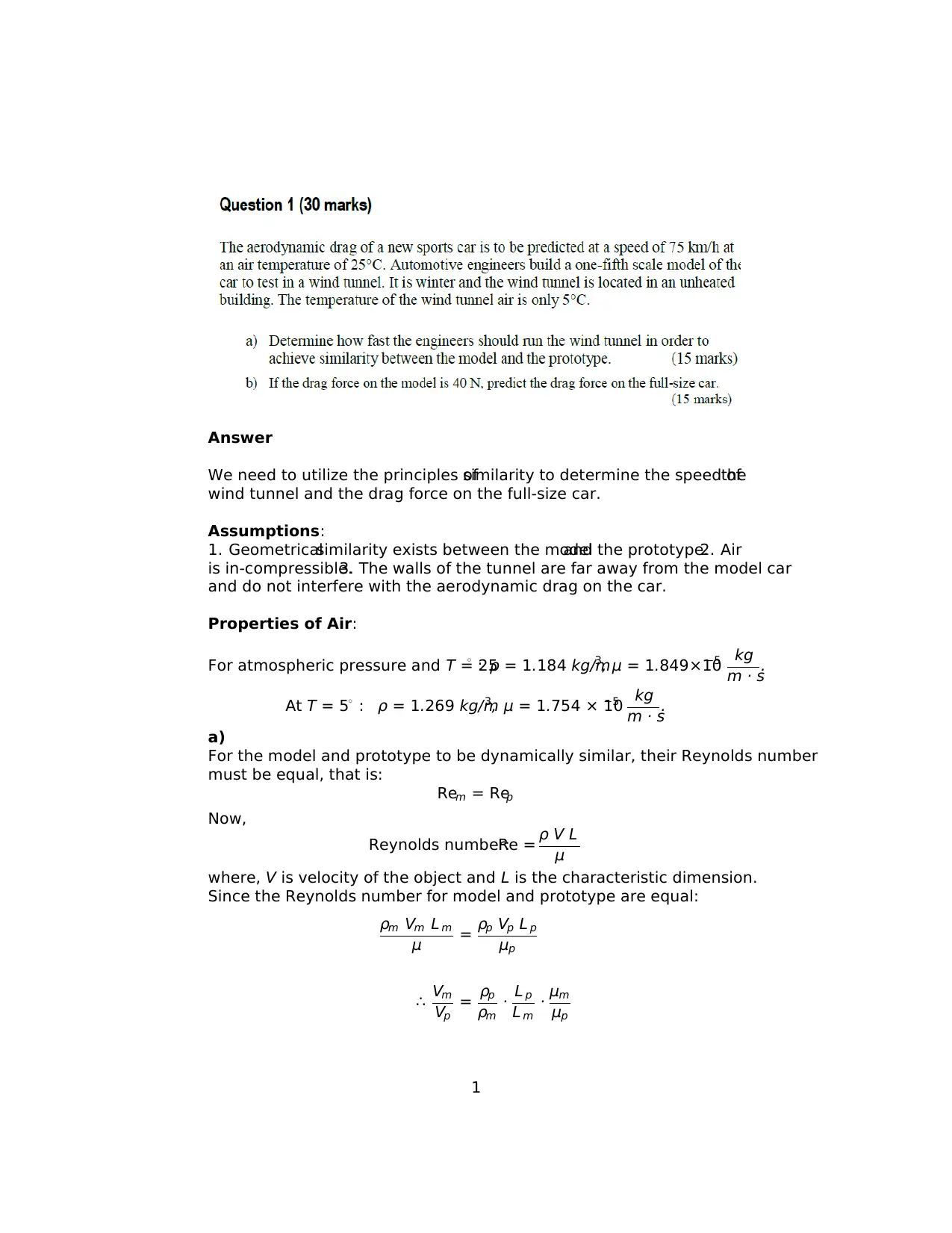
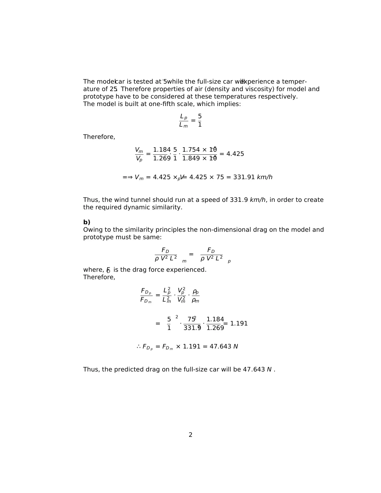
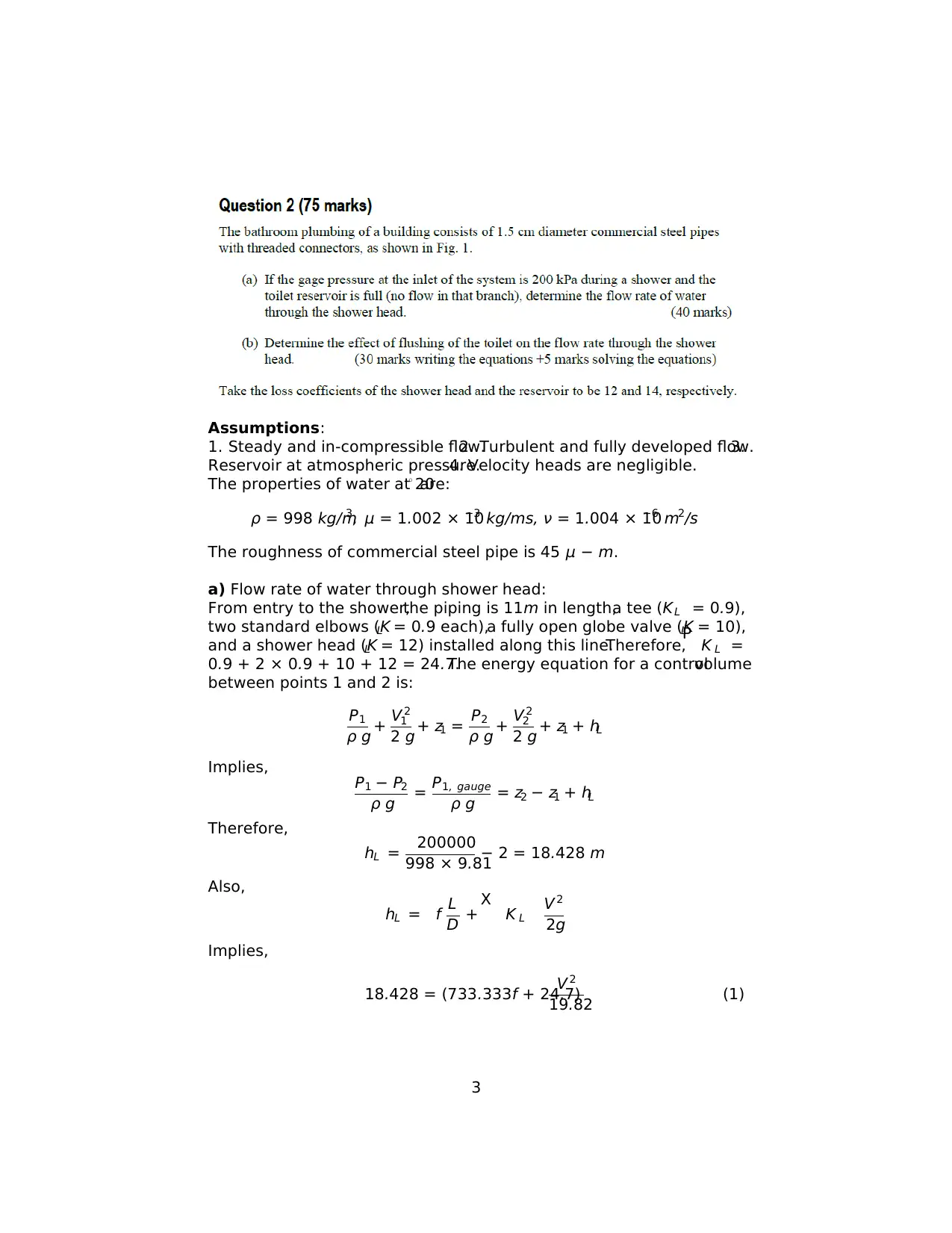
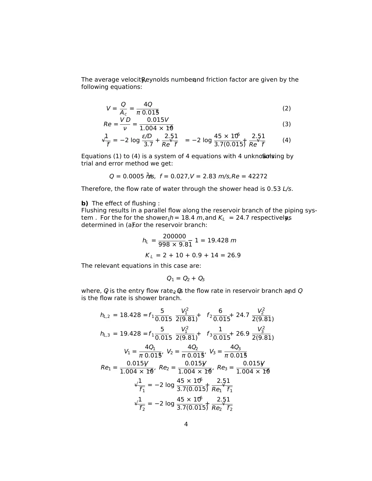
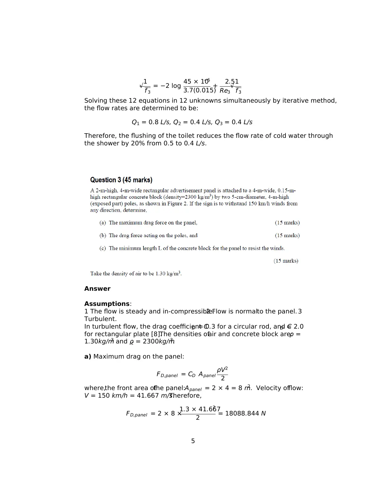
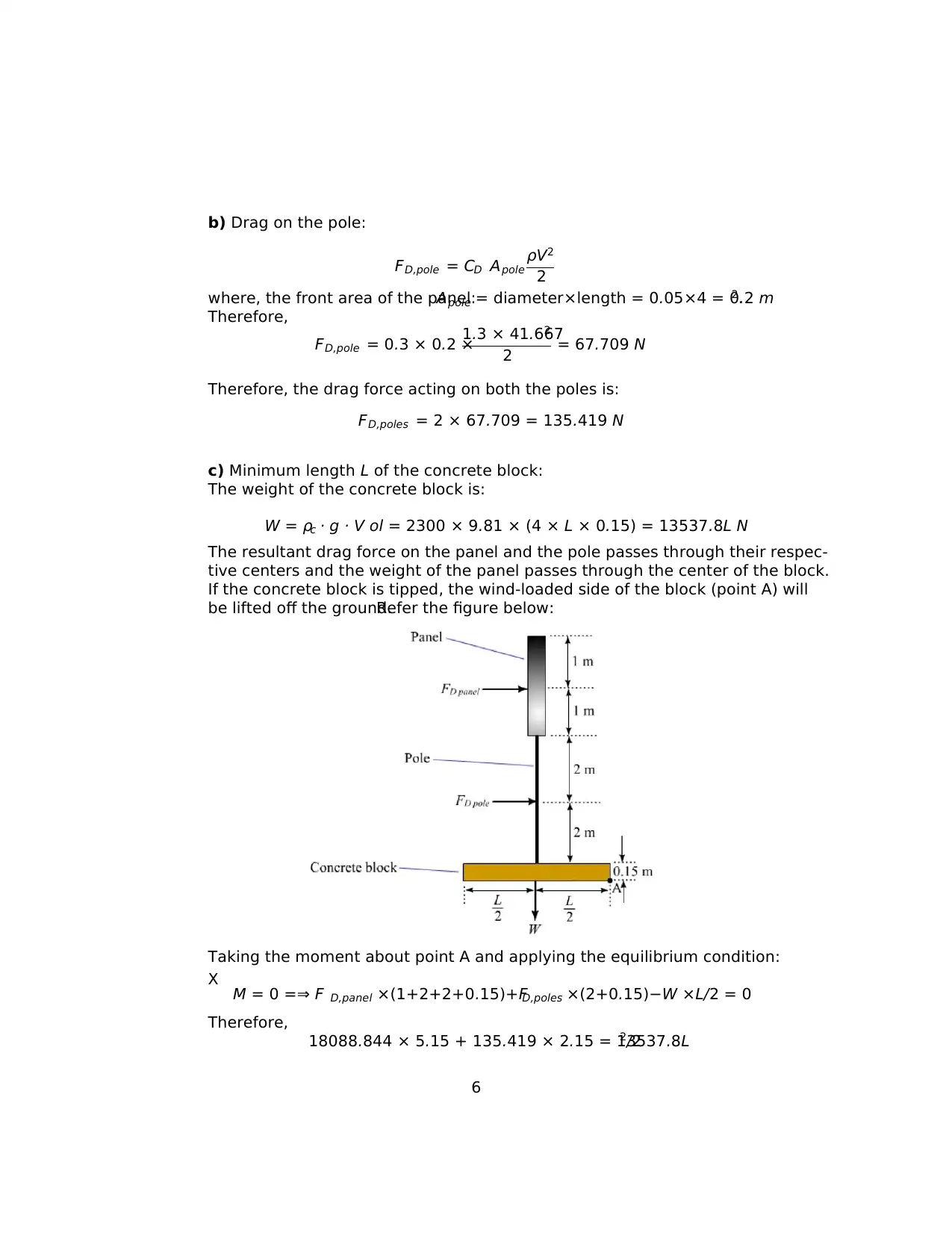
This document provides comprehensive solutions to MEC3102 Assignment 2, focusing on fluid mechanics principles. The first problem addresses aerodynamic drag prediction for a sports car, utilizing a scaled wind tunnel model. It involves calculating the wind tunnel speed required for dynamic similarity based on Reynolds number and predicting the drag force on the full-size car. The second problem analyzes a bathroom plumbing system, determining the flow rate through a shower head and assessing the impact of toilet flushing on the flow rate. This includes applying the energy equation, calculating the friction factor, and solving a system of equations using iterative methods. The final problem examines the drag forces acting on a panel and a pole subjected to wind, along with calculating the minimum length of a concrete block required to prevent tipping, considering the combined effect of drag and weight. The solutions are detailed, including assumptions, sketches, and step-by-step calculations.

Answer
We need to utilize the principles ofsimilarity to determine the speed ofthe
wind tunnel and the drag force on the full-size car.
Assumptions:
1. Geometricalsimilarity exists between the modeland the prototype.2. Air
is in-compressible.3. The walls of the tunnel are far away from the model car
and do not interfere with the aerodynamic drag on the car.
Properties of Air:
For atmospheric pressure and T = 25◦ : ρ = 1.184 kg/m3, μ = 1.849×10⁻⁵ kg
m · s
.
At T = 5◦ : ρ = 1.269 kg/m3, μ = 1.754 × 10⁻⁵ kg
m · s
.
a)
For the model and prototype to be dynamically similar, their Reynolds number
must be equal, that is:
Rem = Rep
Now,
Reynolds number:Re = ρ V L
μ
where, V is velocity of the object and L is the characteristic dimension.
Since the Reynolds number for model and prototype are equal:
ρm Vm L m
μ = ρp Vp L p
μp
∴ Vm
Vp
= ρp
ρm
· L p
L m
· μm
μp
1
Paraphrase This Document
Need a fresh take? Get an instant paraphrase of this document with our AI Paraphraser

The modelcar is tested at 5◦ while the full-size car willexperience a temper-
ature of 25◦. Therefore properties of air (density and viscosity) for model and
prototype have to be considered at these temperatures respectively.
The model is built at one-fifth scale, which implies:
L p
L m
= 5
1
Therefore,
Vm
Vp
= 1.184
1.269
· 5
1 · 1.754 × 10−5
1.849 × 10−5 = 4.425
=⇒ Vm = 4.425 × Vp = 4.425 × 75 = 331.91 km/h
Thus, the wind tunnel should run at a speed of 331.9 km/h, in order to create
the required dynamic similarity.
b)
Owing to the similarity principles the non-dimensional drag on the model and
prototype must be same:
FD
ρ V2 L 2 m
= FD
ρ V2 L 2 p
where, FD is the drag force experienced.
Therefore,
FD p
FD m
= L 2
p
L 2
m
· V 2
p
V 2
m
· ρp
ρm
= 5
1
2
· 752
331.92 · 1.184
1.269= 1.191
∴ FD p = FD m × 1.191 = 47.643 N
Thus, the predicted drag on the full-size car will be 47.643 N .
2

Assumptions:
1. Steady and in-compressible flow.2. Turbulent and fully developed flow.3.
Reservoir at atmospheric pressure.4. Velocity heads are negligible.
The properties of water at 20◦ are:
ρ = 998 kg/m3, μ = 1.002 × 10⁻³ kg/ms, ν = 1.004 × 10⁻⁶ m2/s
The roughness of commercial steel pipe is 45 μ − m.
a) Flow rate of water through shower head:
From entry to the shower,the piping is 11m in length,a tee (KL = 0.9),
two standard elbows (KL = 0.9 each),a fully open globe valve (KL = 10),
and a shower head (KL = 12) installed along this line.Therefore,
P K L =
0.9 + 2 × 0.9 + 10 + 12 = 24.7.The energy equation for a controlvolume
between points 1 and 2 is:
P1
ρ g + V 2
1
2 g + z1 = P2
ρ g + V 2
2
2 g + z1 + hL
Implies, P1 − P2
ρ g = P1, gauge
ρ g = z2 − z1 + hL
Therefore,
hL = 200000
998 × 9.81
− 2 = 18.428 m
Also,
hL = f L
D + X K L
V 2
2g
Implies,
18.428 = (733.333f + 24.7)
V 2
19.82 (1)
3
You're viewing a preview
Unlock full access by subscribing today!

The average velocity,Reynolds number,and friction factor are given by the
following equations:
V = Q
Ac
= 4Q
π 0.0152 (2)
Re = V D
ν = 0.015V
1.004 × 10⁻⁶ (3)
1
√ f = −2 log ε/D
3.7 + 2.51
Re√ f = −2 log 45 × 10−6
3.7(0.015)
+ 2.51
Re√ f (4)
Equations (1) to (4) is a system of 4 equations with 4 unknowns.Solving by
trial and error method we get:
Q = 0.0005 m3/s, f = 0.027,V = 2.83 m/s,Re = 42272
Therefore, the flow rate of water through the shower head is 0.53 L/s.
b) The effect of flushing :
Flushing results in a parallel flow along the reservoir branch of the piping sys-
tem . For the for the shower hL = 18.4 m,and KL = 24.7 respectively,as
determined in (a).For the reservoir branch:
hL = 200000
998 × 9.81
− 1 = 19.428 m
K L = 2 + 10 + 0.9 + 14 = 26.9
The relevant equations in this case are:
Q1 = Q2 + Q3
where, Q1 is the entry flow rate, Q2 is the flow rate in reservoir branch and Q3
is the flow rate is shower branch.
hL,2 = 18.428 = f 1
5
0.015
V 2
1
2(9.81)
+ f 2
6
0.015
+ 24.7 V 2
2
2(9.81)
hL,3 = 19.428 = f 1
5
0.015
V 2
1
2(9.81)
+ f 3
1
0.015
+ 26.9 V 2
3
2(9.81)
V1 = 4Q1
π 0.0152 , V2 = 4Q2
π 0.0152 , V3 = 4Q3
π 0.0152
Re1 = 0.015V1
1.004 × 10⁻⁶ , Re2 = 0.015V2
1.004 × 10⁻⁶ , Re3 = 0.015V3
1.004 × 10⁻⁶
1
√ f 1
= −2 log 45 × 10−6
3.7(0.015)
+ 2.51
Re1
√ f 1
1
√ f 2
= −2 log 45 × 10−6
3.7(0.015)
+ 2.51
Re2
√ f 2
4
Paraphrase This Document
Need a fresh take? Get an instant paraphrase of this document with our AI Paraphraser

1
√ f 3
= −2 log 45 × 10−6
3.7(0.015)
+ 2.51
Re3
√ f 3
Solving these 12 equations in 12 unknowns simultaneously by iterative method,
the flow rates are determined to be:
Q1 = 0.8 L/s, Q2 = 0.4 L/s, Q3 = 0.4 L/s
Therefore, the flushing of the toilet reduces the flow rate of cold water through
the shower by 20% from 0.5 to 0.4 L/s.
Answer
Assumptions:
1 The flow is steady and in-compressible.2 Flow is normalto the panel. 3
Turbulent.
In turbulent flow, the drag coefficient CD = 0.3 for a circular rod, and CD = 2.0
for rectangular plate [8].The densities ofair and concrete block are:ρ =
1.30kg/m3 and ρc = 2300kg/m3.
a) Maximum drag on the panel:
FD,panel = CD Apanel
ρV2
2
where,the front area ofthe panel:Apanel = 2 × 4 = 8 m2. Velocity offlow:
V = 150 km/h = 41.667 m/s.Therefore,
FD,panel = 2 × 8 ×
1.3 × 41.6672
2 = 18088.844 N
5
√ f 3
= −2 log 45 × 10−6
3.7(0.015)
+ 2.51
Re3
√ f 3
Solving these 12 equations in 12 unknowns simultaneously by iterative method,
the flow rates are determined to be:
Q1 = 0.8 L/s, Q2 = 0.4 L/s, Q3 = 0.4 L/s
Therefore, the flushing of the toilet reduces the flow rate of cold water through
the shower by 20% from 0.5 to 0.4 L/s.
Answer
Assumptions:
1 The flow is steady and in-compressible.2 Flow is normalto the panel. 3
Turbulent.
In turbulent flow, the drag coefficient CD = 0.3 for a circular rod, and CD = 2.0
for rectangular plate [8].The densities ofair and concrete block are:ρ =
1.30kg/m3 and ρc = 2300kg/m3.
a) Maximum drag on the panel:
FD,panel = CD Apanel
ρV2
2
where,the front area ofthe panel:Apanel = 2 × 4 = 8 m2. Velocity offlow:
V = 150 km/h = 41.667 m/s.Therefore,
FD,panel = 2 × 8 ×
1.3 × 41.6672
2 = 18088.844 N
5

b) Drag on the pole:
FD,pole = CD Apole
ρV2
2
where, the front area of the panel:Apole = diameter×length = 0.05×4 = 0.2 m2.
Therefore,
FD,pole = 0.3 × 0.2 ×
1.3 × 41.6672
2 = 67.709 N
Therefore, the drag force acting on both the poles is:
FD,poles = 2 × 67.709 = 135.419 N
c) Minimum length L of the concrete block:
The weight of the concrete block is:
W = ρc · g · V ol = 2300 × 9.81 × (4 × L × 0.15) = 13537.8L N
The resultant drag force on the panel and the pole passes through their respec-
tive centers and the weight of the panel passes through the center of the block.
If the concrete block is tipped, the wind-loaded side of the block (point A) will
be lifted off the ground.Refer the figure below:
Taking the moment about point A and applying the equilibrium condition:
X M = 0 =⇒ F D,panel ×(1+2+2+0.15)+FD,poles ×(2+0.15)−W ×L/2 = 0
Therefore,
18088.844 × 5.15 + 135.419 × 2.15 = 13537.8L2/2
6
You're viewing a preview
Unlock full access by subscribing today!

implies,
L = √ 13.806 = 3.716 m
References:
1. B. Rao, Fluid mechanics and machinery.New Delhi,India: Tata Mcgraw
Hill, 2010.
2. G. Biswas,Computationalfluid dynamics.New Delhi,India: Narosa Pub-
lishing House, 2013.
3.G. Buresti,Elements offluid dynamics.London,England:Cambridge Uni-
versity Press, 2012.
4. R. Bansal,Textbook of fluid mechanics and hydraulic machine.New Delhi,
India: Laxmi Publication, 2011.
5. S. Kumar, Fluid mechanics.New Delhi, India:Anne Books, 2010.
6. T. Sengupta, Instabilities of flows and transition to turbulence.Boca Raton,
USA: Taylor Francis, 2012.
7. V. Babu, Fundamentals of incompressible fluid flow.New Delhi, India:Anne
Books Pvt Ltd, 2010
8. Y. Cengel,Fluid mechanics:fundamentals and applications.Boston,USA:
McGraw-Hill Publishing, 2013.
7
1 out of 7

Your All-in-One AI-Powered Toolkit for Academic Success.
+13062052269
info@desklib.com
Available 24*7 on WhatsApp / Email
Unlock your academic potential
© 2024 | Zucol Services PVT LTD | All rights reserved.