Mech2450 Engineering Computations: Assignment 1 - Truss Design
VerifiedAdded on 2023/06/05
|15
|2732
|311
Homework Assignment
AI Summary
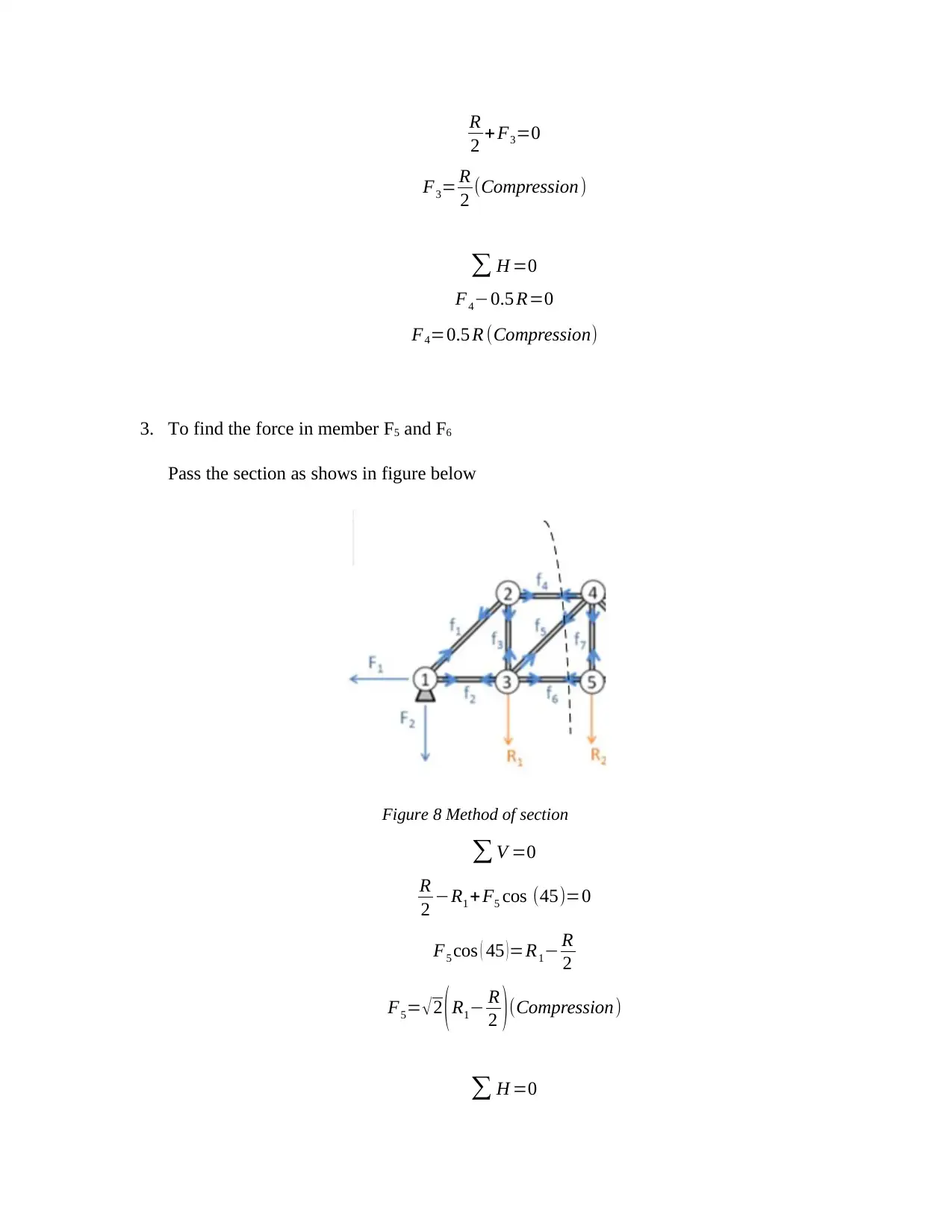
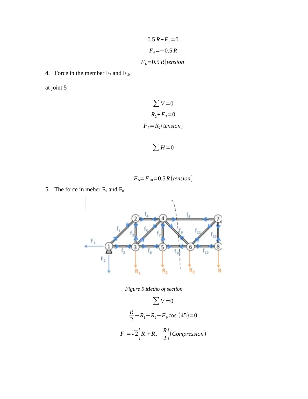
This document provides a solution to a mechanical engineering assignment focused on truss design and analysis, specifically addressing problems related to truss structures supporting wastewater pipelines beneath bridges. The solution covers the calculation of water mass in a trough, analysis of forces acting on truss members using methods of joints and sections, and probabilistic assessment of bridge overloading based on vehicle traffic patterns. The analysis includes considerations for tension and compression forces within truss elements, equilibrium conditions, and the impact of water weight and vehicle loads on the structural integrity of the bridge. MATLAB code is used for calculations, and the design considerations are contextualized with references to various truss bridge types and relevant engineering principles. This assignment solution is available on Desklib, a platform offering study tools and resources for students.

THE UNVIERSITY OF NEWCASTLE
SCHOOL OF ENGINERING
DISCIPLINE OF MECHANICAL ENGINEERING
Mech2450 – Engineering Computations 2
Assignment 1
SCHOOL OF ENGINERING
DISCIPLINE OF MECHANICAL ENGINEERING
Mech2450 – Engineering Computations 2
Assignment 1
Paraphrase This Document
Need a fresh take? Get an instant paraphrase of this document with our AI Paraphraser

Solution 1:
Introduction
Here three problems have been asked which is based on the problem of truss design and weight
or forces acting on the members of truss as well as design analysis of water waste pipeline which
cross the ravine using a trough slung below the bridge. The challenging part is the design of
bridge with slung of waste water pipe where weight of bridge, weight of vehicle and the weight
of pipeline addition may cause catastrophe. Truss are generally made of combination of
triangles; some truss might have different combination of design structure[1].
Translation
The total mass of water in the trough at any given time is given by the expression:
Figure 1 water slung beneath the bridge
Where m [kg] is the mass of water in the trough, r [m] is the trough radius, L [m] is the length of
the trough, and h [m] is the height of water from the top of the trough.
Methodology
The MATLAB code for the give problem and equation is presented in appendix at the last of the
report. From the given equation of mass which is having terms, radius of half cylindrical open
pipe, length and height. For the given value of length, radius and mass, the height from the top of
the trough is derived using MATLAB with the help of for loop.

Result & Discussion
Figure 2 Truss structure
Solution: 2
Introduction:
When bridge or roof top structure made with truss subjected to various reaction forces acting in
horizontal and vertical directions. As well each member of truss may subject to tension and
compression. In bridge design truss are very common if truss is not used in bridge construction
than it may be made of simple beam connection. Very common truss designs are warren truss[2],
pratt truss[3], howe truss[4], K truss[5] etc. In the design procedure of the truss along with the
newtons law of motion many other things are taken into consideration. The joint also plays
important role in truss design. Very common joints are pin joint at where member of truss meet
at that point[6]. Also, the forces of compression and the tension acts upon the member of the
truss[7]
⊘ This is a preview!⊘
Do you want full access?
Subscribe today to unlock all pages.

Trusted by 1+ million students worldwide

Figure 3 Bridge truss and water pipe
Translation:
The total mass of water in the trough at any given time is given by the expression:
Where m [kg] is the mass of water in the trough, r [m] is the trough radius, L [m] is the length of
the trough, and h [m] is the height of water from the top of the trough.
Derive the equation in terms of h.
Methodology:
The methodology opted for truss design calculation is the equilibrium equations. Which is The
summation of the forces at a assumed point is always zero.
∑ M =0
With the simple concept of vectors, So according to the equilibrium equations
∑ Fx=0
Similarly, the sum of the forces acting upon the Y direction also zero.
Paraphrase This Document
Need a fresh take? Get an instant paraphrase of this document with our AI Paraphraser

∑ Fy=0
Two common methods are methods of joins and method of sections are use for truss analysis.
Both the methods are explained in the next section, here in our example we opted method of
section for the solution of numerical[8]. And the A force that causes a counterclockwise moment
is positive moment. Stress that the only forces used when summing the moments are the external
forces. Members’ internal forces are not used[9]. Note: Choose the point that we will use as our
"pivot" when summing the moments[10].
Using the concept of trigonometry cosine and sine which helps in finding the vectors x and y.
Lets assume that all elements of the truss are subjected to the tension, if answer is positive it
means all the element is in tension and if the answer is negative it means element is subjected to
compression[11].
As from the previous assumption if sing of answer is different need to update the free body
diagram with the right magnitude and direction. If the direction of a member force changes, there
will be two free body diagrams that need to be updated[12].
For example, here by making free body diagram for elements. Some random forces are shown
with some magnitude.

Figure 4 Point support and various forces
Each and every element of the truss assumed to be subjected to tension[13]. If the sign of answer
is positive it means the element is subjected to tension and the minus sign means it is subjected
to compression. The selected joint must have at lease two unknowns. Here in below diagram
reaction forces at A and C are better to select to start the calculations.
Figure 5 Point support and various forces
⊘ This is a preview!⊘
Do you want full access?
Subscribe today to unlock all pages.

Trusted by 1+ million students worldwide

Figure 6 Method of section
Method of joints explained in the above section. In our assignment method of section is
followed. As the name suggest, truss design is divided into various section and each section are
analysed for the forces action upon the members. For example, here in below figure whole truss
section is divided into and section is shown by dashed line. From this section model we will be
able to find the forces acting upon the member 2-4, 2-3, and 1-3. In the next step moving towards
the opposite direction and next section is made and the forces are determined. If truss structure is
symmetrical it is easy to find the forces in other members due to symmetry of truss structure.
Steps:
Make cut or reduce the truss structure design split it with sectional line put it where the forces are
needed to be determined. Make cut at least in two section because at least two equilibrium forces
are needed to be find. At the last step apply equilibrium condition and find forces in all the
members.
The Length of the bridge = 50m
Length/member =50/6=8.33 m
Assuming Height of member =8.33 m
Paraphrase This Document
Need a fresh take? Get an instant paraphrase of this document with our AI Paraphraser

The total load carried is R1 +R2 + R3 +R4 + R5=R
Reactions are given as F2=F3 = R
2 in upward direction
1. Lets consider the joint 1
∑ V =0
R
2 +F1 sin ( 45 )=0
F1=−R/2 sin (45)
F1=−0.7071 R
F1=0.7071 R (tension)
Now
∑ H =0
F2−F1 cos ( 45 )=0
F2=F1 cos ( 45 )
F2=0.7071 R cos ( 45 )
F2=0.5 R ( tension )
2. To find the force in member 2-3 Pass a section as shown in figure below
Figure 7 Method of section
∑ V =0

R
2 + F3=0
F3= R
2 (Compression)
∑ H =0
F4−0.5 R=0
F4=0.5 R (Compression)
3. To find the force in member F5 and F6
Pass the section as shows in figure below
Figure 8 Method of section
∑ V =0
R
2 −R1 +F5 cos (45)=0
F5 cos ( 45 ) =R1− R
2
F5= √2 (R1− R
2 )(Compression)
∑ H =0
2 + F3=0
F3= R
2 (Compression)
∑ H =0
F4−0.5 R=0
F4=0.5 R (Compression)
3. To find the force in member F5 and F6
Pass the section as shows in figure below
Figure 8 Method of section
∑ V =0
R
2 −R1 +F5 cos (45)=0
F5 cos ( 45 ) =R1− R
2
F5= √2 (R1− R
2 )(Compression)
∑ H =0
⊘ This is a preview!⊘
Do you want full access?
Subscribe today to unlock all pages.

Trusted by 1+ million students worldwide

0.5 R+ F6=0
F6=−0.5 R
F6=0.5 R ( tension )
4. Force in the member F7 and F10
at joint 5
∑ V =0
R2 + F7=0
F7=R2 (tension)
∑ H =0
F6=F10=0.5 R (tension)
5. The force in meber F9 and F8
Figure 9 Metho of section
∑ V =0
R
2 −R1−R2−F9 cos (45)=0
F9= √2 (R1 + R2− R
2 )(Compression)
F6=−0.5 R
F6=0.5 R ( tension )
4. Force in the member F7 and F10
at joint 5
∑ V =0
R2 + F7=0
F7=R2 (tension)
∑ H =0
F6=F10=0.5 R (tension)
5. The force in meber F9 and F8
Figure 9 Metho of section
∑ V =0
R
2 −R1−R2−F9 cos (45)=0
F9= √2 (R1 + R2− R
2 )(Compression)
Paraphrase This Document
Need a fresh take? Get an instant paraphrase of this document with our AI Paraphraser

∑ H =0
F8−0.5 R+ √ 2 ( R1 + R2− R
2 ) cos ( 45 ) =0
F8=0.5 R−R1−R2 + R
2 =R−R1 + R2 (Compression)
As the truss is symmetrical the forces in all other members are same as calculated above
Weight of water =50,000 kg=50,000X10 N
=500 kN=R
Let R1=R2=R3=R4=R5 =500
5 =100 kN
So the forces in the members are given as below
F1=0.7071 R=70.71 kN (T )
F2=0.5 R=250 kN (T )
F3=R/2=250 kN (C)
F4=0.5 R=250 kN (C )
F5=−212.13 kN (T )
F6=0.5 R=250 kN (T )
F7=100 kN (T )
F8=300 kN (C)
F10=0.5 R=250 kN (T )
Solution 3:
Introduction
Hilltown bridge designed here was originally use for heavy vehicles and it was subjected
to risk of overloading. And the total limit over loading and forces on truss element was
kept 550 kN. So the use of bridge as transportation way limited to only 5 vehicles at a
time. The force applied on reaction points subjected to type of vehicle passing over the

bridge. Where truck considered to be applying 50 kN and car 15 kN during three time
slot intervals
Translation
To solve the problem poisson distribution given and solution based on probabilistic
P ( x ;m )=P ( 6 ;5 )= e−m . mn
n !
And for the three condition of vehicles passing equation can be formed as below,
E ( early )=∑
i=1
3
Pi xi
Methodology
Given the bridge is considered to be overloaded with forces in any truss element exceeds
550 kN.
At any time, there may be up to 5 vehicles on the bridge are present
Mean=5
Solution 3 (a): The question is a poisson distribution mean=5 (as per the given data)
So, if number of vehicles exceeds more than 5 then bridge will be overloaded
Take number of vehicles n=6 for overloading bridge at any time
So
P ( x ;m )=P ( 6 ;5 )= e−m . mn
n !
¿ e−5 . 56
6 !
¿ (0.006737)(15625)
720
¿ 0.146
⊘ This is a preview!⊘
Do you want full access?
Subscribe today to unlock all pages.

Trusted by 1+ million students worldwide
1 out of 15
Your All-in-One AI-Powered Toolkit for Academic Success.
+13062052269
info@desklib.com
Available 24*7 on WhatsApp / Email
Unlock your academic potential
Copyright © 2020–2026 A2Z Services. All Rights Reserved. Developed and managed by ZUCOL.