Mechanical Principles Report: Analysis of BMW Mechanical Systems
VerifiedAdded on 2023/06/10
|19
|2086
|413
Report
AI Summary
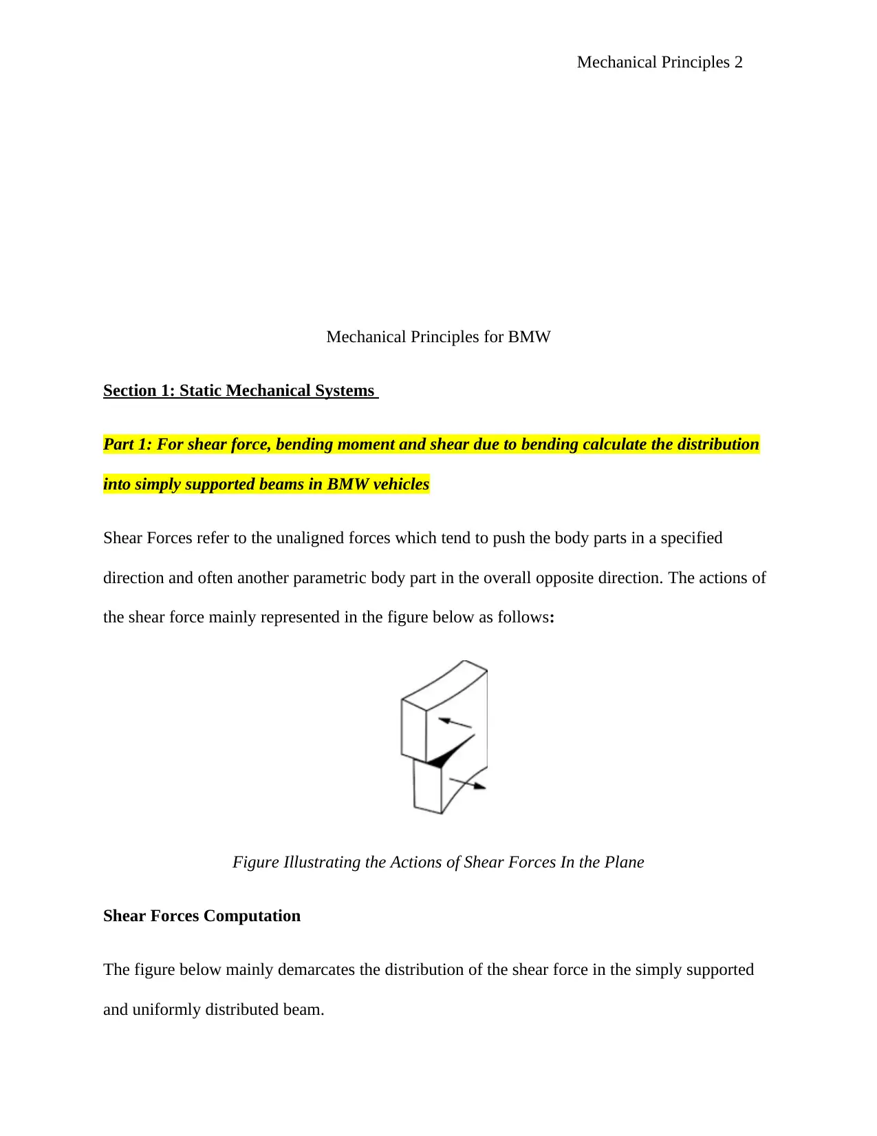
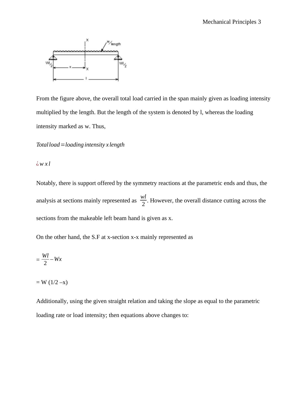
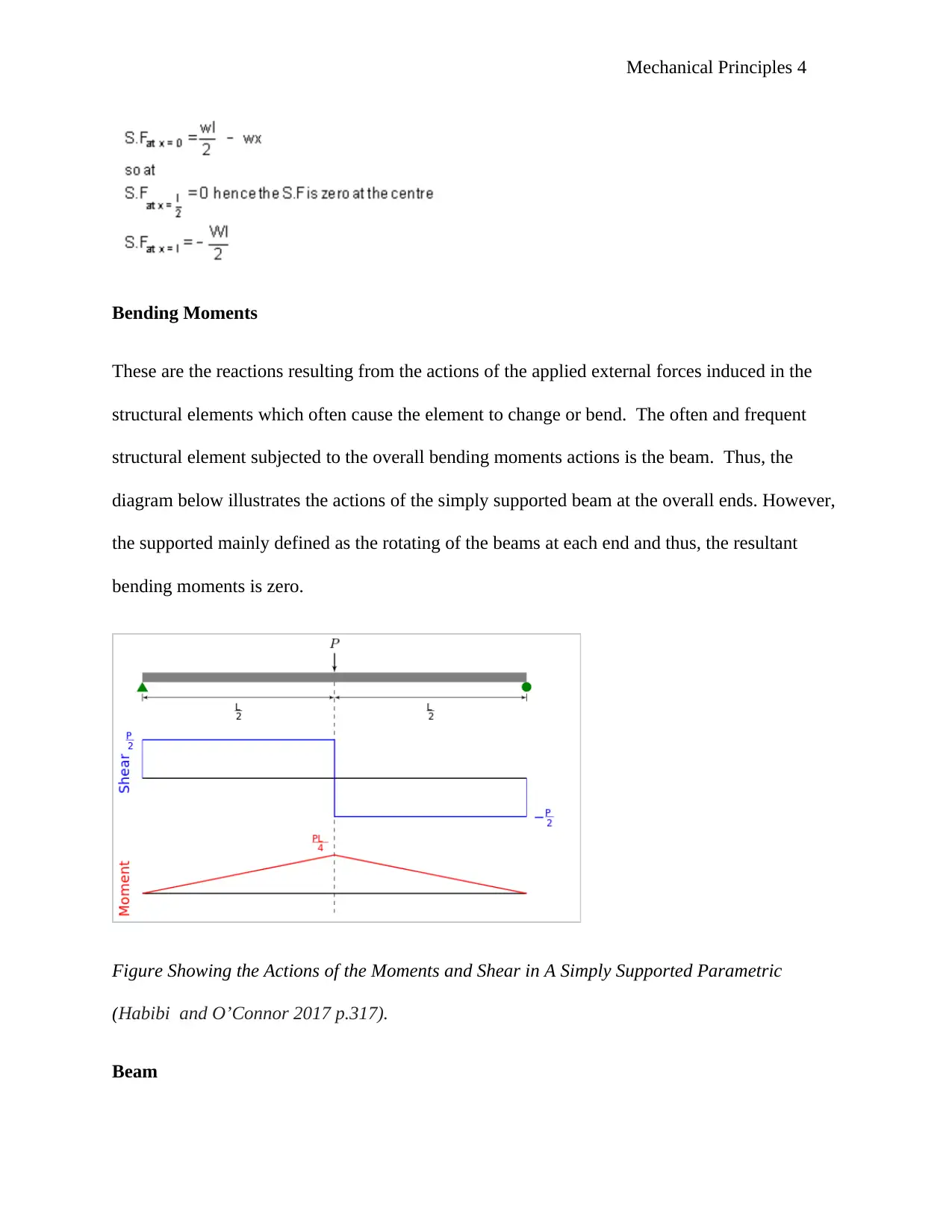
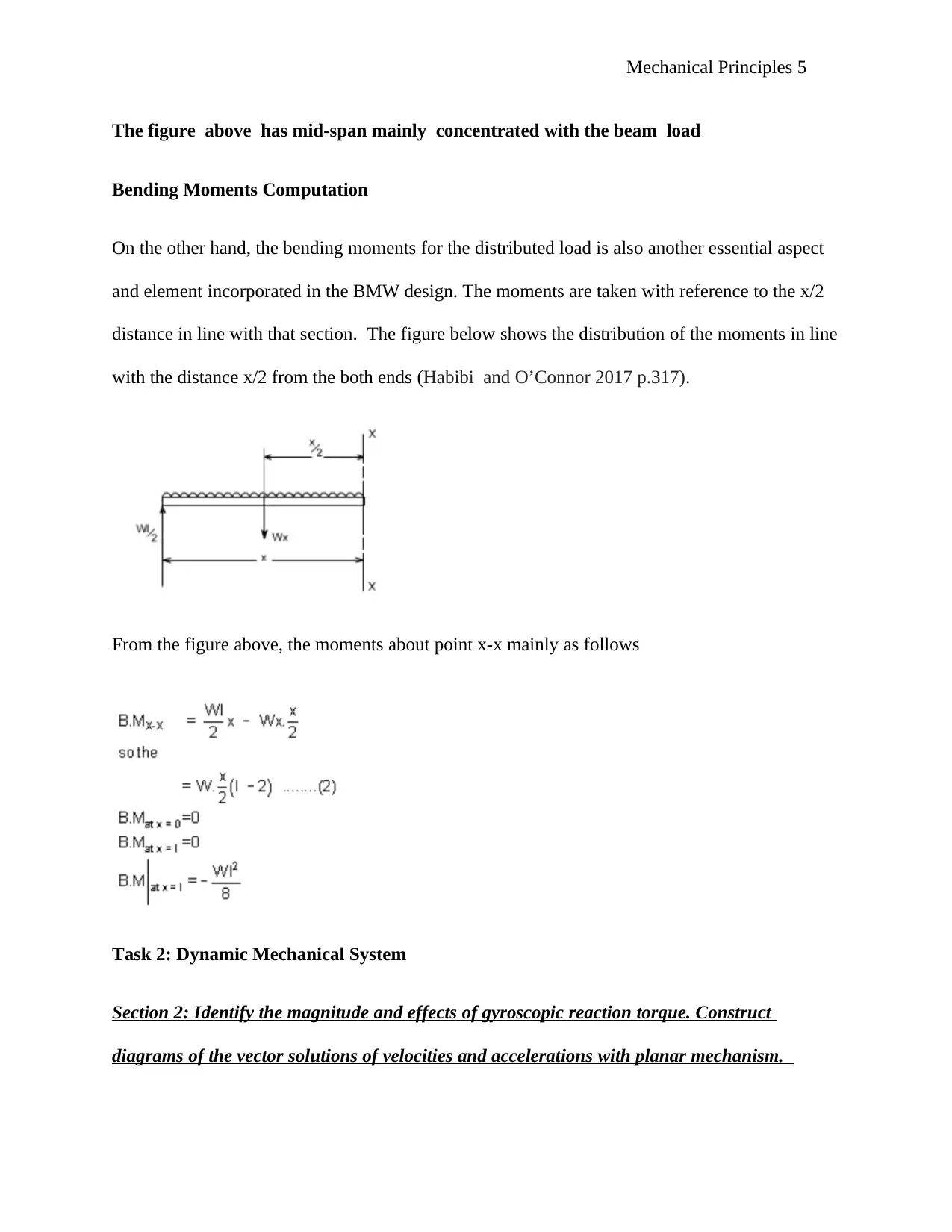
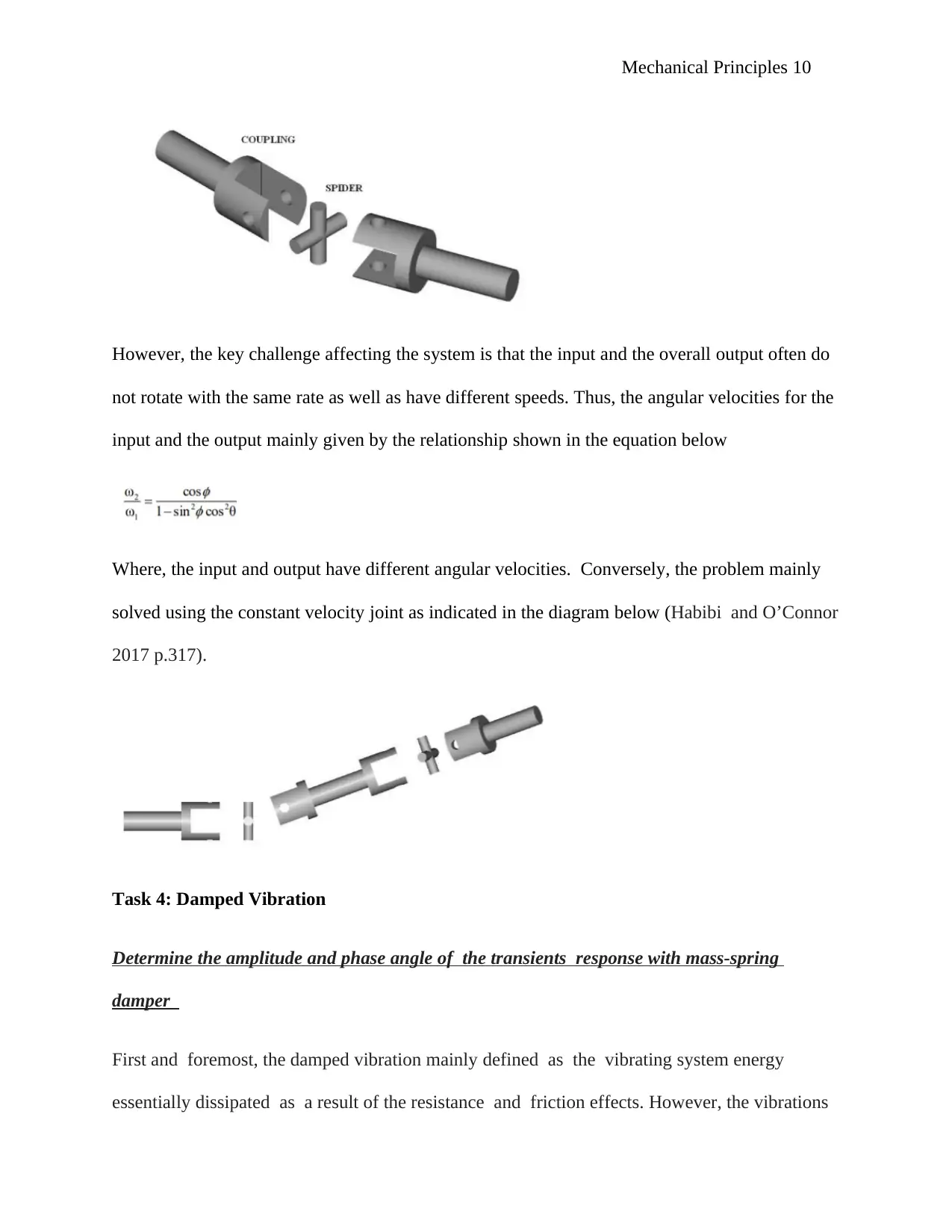
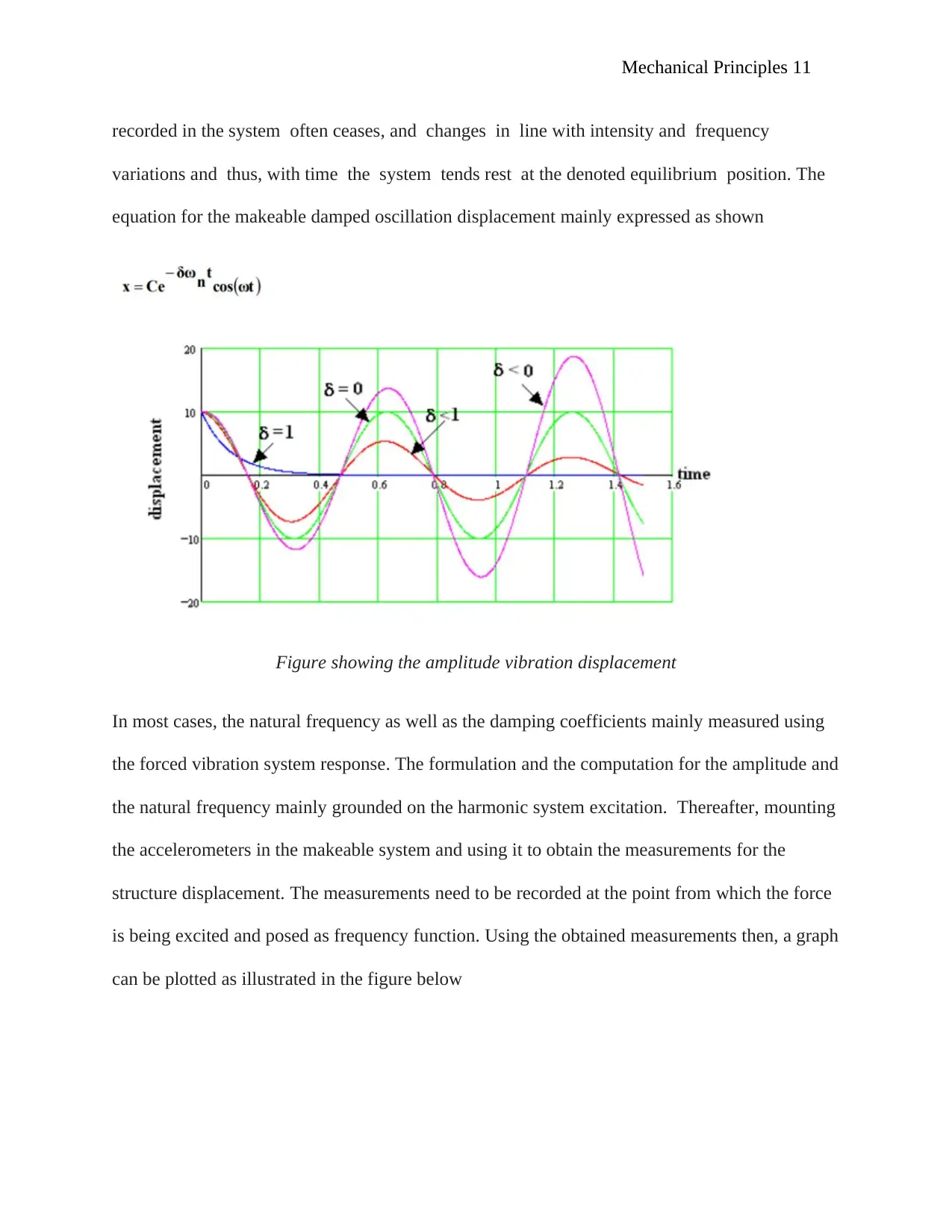
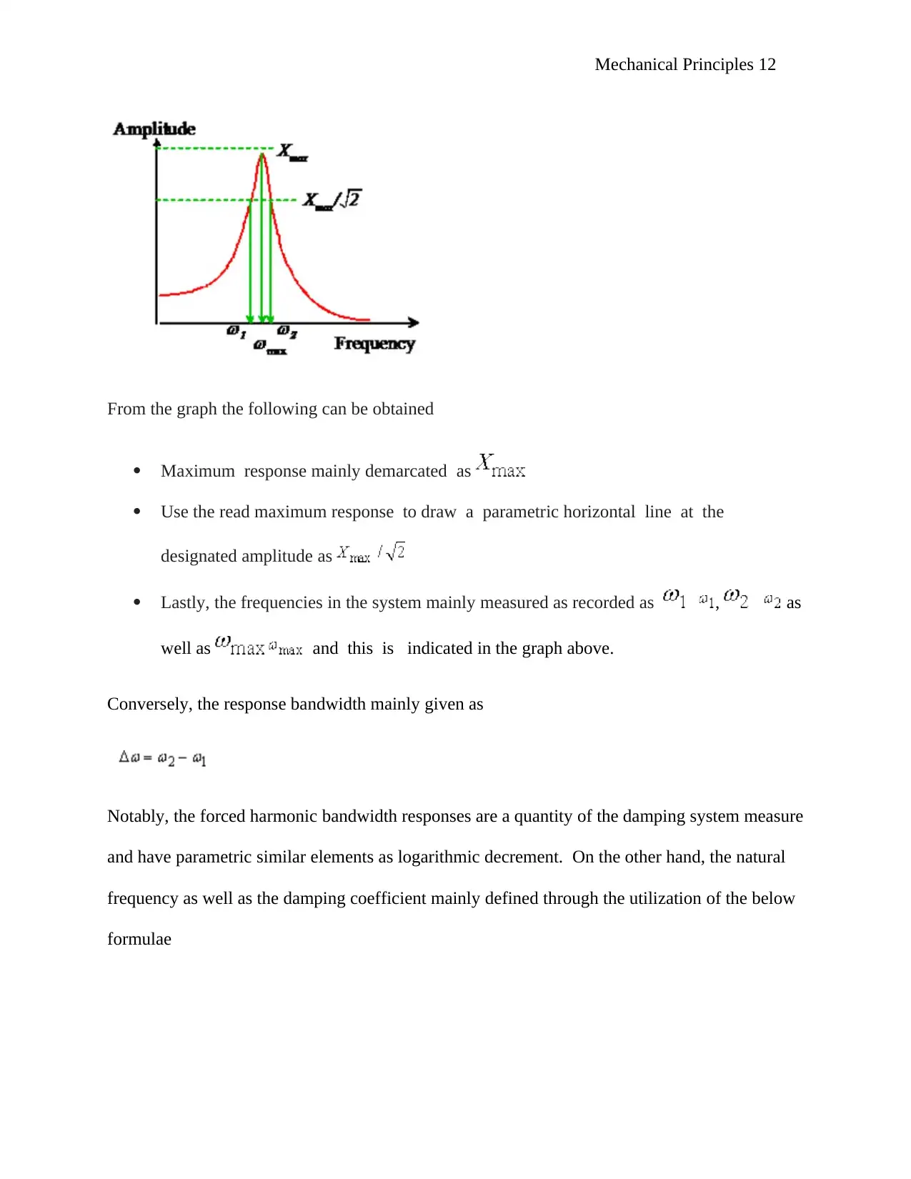
This report delves into the mechanical principles underpinning BMW vehicles, encompassing static and dynamic mechanical systems. It examines shear forces, bending moments in simply supported beams, and the effects of gyroscopic reaction torque. The report also explores mechanical power transmission systems, focusing on constant velocity joints and damped vibrations, including amplitude and phase angle analysis. Additionally, it addresses energy transfer in mechanical systems with uniform accelerations and calculates the operating efficiency of lead screws and screw jacks. Furthermore, the report investigates material determination from torsion tests and analyzes a case of mechanical power transmission failure, outlining corrective measures. The content provides a comprehensive overview of mechanical engineering concepts relevant to automotive design and analysis.

Mechanical Principles 1
Mechanical Principles
by Student’s Name
Code + Course Name
Professor’s Name
University Name
City, State
Date
Mechanical Principles
by Student’s Name
Code + Course Name
Professor’s Name
University Name
City, State
Date
Secure Best Marks with AI Grader
Need help grading? Try our AI Grader for instant feedback on your assignments.

Mechanical Principles 2
Mechanical Principles for BMW
Section 1: Static Mechanical Systems
Part 1: For shear force, bending moment and shear due to bending calculate the distribution
into simply supported beams in BMW vehicles
Shear Forces refer to the unaligned forces which tend to push the body parts in a specified
direction and often another parametric body part in the overall opposite direction. The actions of
the shear force mainly represented in the figure below as follows:
Figure Illustrating the Actions of Shear Forces In the Plane
Shear Forces Computation
The figure below mainly demarcates the distribution of the shear force in the simply supported
and uniformly distributed beam.

Mechanical Principles 3
From the figure above, the overall total load carried in the span mainly given as loading intensity
multiplied by the length. But the length of the system is denoted by l, whereas the loading
intensity marked as w. Thus,
Total load=loading intensity x length
¿ w x l
Notably, there is support offered by the symmetry reactions at the parametric ends and thus, the
analysis at sections mainly represented as wl
2 . However, the overall distance cutting across the
sections from the makeable left beam hand is given as x.
On the other hand, the S.F at x-section x-x mainly represented as
= Wl
2 – Wx
= W (1/2 –x)
Additionally, using the given straight relation and taking the slope as equal to the parametric
loading rate or load intensity; then equations above changes to:

Mechanical Principles 4
Bending Moments
These are the reactions resulting from the actions of the applied external forces induced in the
structural elements which often cause the element to change or bend. The often and frequent
structural element subjected to the overall bending moments actions is the beam. Thus, the
diagram below illustrates the actions of the simply supported beam at the overall ends. However,
the supported mainly defined as the rotating of the beams at each end and thus, the resultant
bending moments is zero.
Figure Showing the Actions of the Moments and Shear in A Simply Supported Parametric
(Habibi and O’Connor 2017 p.317).
Beam
Secure Best Marks with AI Grader
Need help grading? Try our AI Grader for instant feedback on your assignments.

Mechanical Principles 5
The figure above has mid-span mainly concentrated with the beam load
Bending Moments Computation
On the other hand, the bending moments for the distributed load is also another essential aspect
and element incorporated in the BMW design. The moments are taken with reference to the x/2
distance in line with that section. The figure below shows the distribution of the moments in line
with the distance x/2 from the both ends (Habibi and O’Connor 2017 p.317).
From the figure above, the moments about point x-x mainly as follows
Task 2: Dynamic Mechanical System
Section 2: Identify the magnitude and effects of gyroscopic reaction torque. Construct
diagrams of the vector solutions of velocities and accelerations with planar mechanism.

Mechanical Principles 6
The effects and the reaction torque magnitude of the gyroscopes in the BMW vehicles
mainly depicted as illustrated in the diagram below
Consider that the flywheel of the vehicle is moving about the given x-axis and it has a velocity of
wx as indicated in the diagram. Thus, the angular momentum for the overall flywheel disc is
given as by L= lwx. The angular momentum of the system mainly defined as the vector quantity
and thus, it is illustrated by vector drawing which must conform to the overall corkscrew rule.
On the other hand, the rotation of the disc in y-direction and y-axis with a small angle ƥ, then a
change in the direction will be recorded for L but it will not have a magnitude. The norm induces
a change in the angular moment mainly illustrated as
This can be illustrated in the vector diagram mainly as follows

Mechanical Principles 7
Figure Illustrating the Vector Diagram for the Effects of Gyroscopic
The above vector representing the overall change in the makeable radius arc mainly established
as Iwx and the angle ƥ. However, the flywheel length mainly defined as the product of the angle
and the radius. The resultant equation mainly given as
Conversely, the second law of Newton’s motion for the rotating bodies indicates that the
variation in the momentum essentially appraised via the application of the torque.
Thus,
Given, that the spinning of the flywheel mainly occurred in time, t seconds, then the momentum
change results in:
Subsequently, the angular velocity wy in the system mainly given as
Paraphrase This Document
Need a fresh take? Get an instant paraphrase of this document with our AI Paraphraser

Mechanical Principles 8
Hence, Torque Rate,
The computed torque in the system, is the required torque in the BMW vehicle which need to
be produce change in both the direction and the vector angle. This is also defined as
momentum change. It is important to note that the applied torque often deduces in the direction
and the magnitude. Therefore, careful examination of the vector for given applied torque is
important to deduce the effect in the z-axis. In essence, the production of the torque in the z-axis
often leads to the y-axis rotation under an effect termed as precession (Habibi and O’Connor
2017 p.317).
However, if it happened that there is no application of the torque and the rotation is made, then
the reaction torque will be produced in the system in line with the Newton’s third law of motion.
Thus, the disc will also produce the parametric response torque as illustrated in the figure below

Mechanical Principles 9
Figure illustrating action of Reaction Torque and rotation about y-axis ((Habibi and O’Connor
2017 p.317)
Task 3: Mechanical Power Transmission Systems
Explain the conditions required for a constant velocity between two joined shafts
There is often the challenge when transmitting the shaft from the input to the overall output in
different axis. The remedy to this problem is grounded on the application of the universal
Coupling. This is often estimated to have both the Hardy Spicers and the Hooke’s Joint. The
application must be incorporated in the BMW vehicle since it has a fat moving propeller shaft.
The illustration for the concept mainly demarcated as indicated in the figure below
Illustrating the Shaft Transmission Challenge (Habibi and O’Connor 2017 p.317)
Universal joint mainly described as illustrated in the figure below

Mechanical Principles 10
However, the key challenge affecting the system is that the input and the overall output often do
not rotate with the same rate as well as have different speeds. Thus, the angular velocities for the
input and the output mainly given by the relationship shown in the equation below
Where, the input and output have different angular velocities. Conversely, the problem mainly
solved using the constant velocity joint as indicated in the diagram below (Habibi and O’Connor
2017 p.317).
Task 4: Damped Vibration
Determine the amplitude and phase angle of the transients response with mass-spring
damper
First and foremost, the damped vibration mainly defined as the vibrating system energy
essentially dissipated as a result of the resistance and friction effects. However, the vibrations
Secure Best Marks with AI Grader
Need help grading? Try our AI Grader for instant feedback on your assignments.

Mechanical Principles 11
recorded in the system often ceases, and changes in line with intensity and frequency
variations and thus, with time the system tends rest at the denoted equilibrium position. The
equation for the makeable damped oscillation displacement mainly expressed as shown
Figure showing the amplitude vibration displacement
In most cases, the natural frequency as well as the damping coefficients mainly measured using
the forced vibration system response. The formulation and the computation for the amplitude and
the natural frequency mainly grounded on the harmonic system excitation. Thereafter, mounting
the accelerometers in the makeable system and using it to obtain the measurements for the
structure displacement. The measurements need to be recorded at the point from which the force
is being excited and posed as frequency function. Using the obtained measurements then, a graph
can be plotted as illustrated in the figure below

Mechanical Principles 12
From the graph the following can be obtained
Maximum response mainly demarcated as
Use the read maximum response to draw a parametric horizontal line at the
designated amplitude as
Lastly, the frequencies in the system mainly measured as recorded as , as
well as and this is indicated in the graph above.
Conversely, the response bandwidth mainly given as
Notably, the forced harmonic bandwidth responses are a quantity of the damping system measure
and have parametric similar elements as logarithmic decrement. On the other hand, the natural
frequency as well as the damping coefficient mainly defined through the utilization of the below
formulae

Mechanical Principles 13
First and foremost, the vibration amplitude as a result of external forcing mainly
Conversely, the maximum amplitude is essentially computed by differentiating the frequency. In
essence, in the computation of the maximum amplitude the derivation is set at zero and then the
overall frequency equation (Habibi and O’Connor 2017 p.317). Thus, the overall maximum
amplitude is given as
The expression for the bandwidth to mainly base on the amplitude maximum
vibration computed as .
For rotor rotation excitation equation mainly posed as shown below
Thus, the equation above summarized as shown below
Paraphrase This Document
Need a fresh take? Get an instant paraphrase of this document with our AI Paraphraser

Mechanical Principles 14
Steady state equation solution for the rotor excitation mainly depicted as indicated below
Thus, the graph below mainly used in giving the functions for the phase and the amplitude of
the rotor rotation
Figure showing amplitude figure showing phase
The motion equations for the amplitude and the phase mainly illustrated as shown below
The first part mainly given as transient response often increases and at large time is parametric
zero (Wang et al. 2018 p.61).
Explain the effects of Energy Transfer in Mechanical Systems with Uniform accelerations
The effects of the parametric energy transfers in line with the overall mechanical systems in
which there is uniform accelerations indicates that the mechanism movements with a constant
rate. Thus, there are no actual energy transfers as per the analysis on the mechanical system.

Mechanical Principles 15
Moreover, no amount of energy transfers will be evident or recorded towards the work input as
well as the mechanical system.
P7. Calculate the operating efficiency of lead screws and screw jack
Lead Jack
The lead jack mainly illustrated as indicated in the figure below
Screw Jack
The diagram below shows the illustration of a screw jack

Mechanical Principles 16
The computation analysis in line with the efficiency mainly illustrated as follows
M1 Determine the material of a circular bar from experimental data of angle of twist
obtained from a torsion test
Figure below indicated circular bar
The computation analysis in line with the efficiency mainly illustrated as follows
M1 Determine the material of a circular bar from experimental data of angle of twist
obtained from a torsion test
Figure below indicated circular bar
Secure Best Marks with AI Grader
Need help grading? Try our AI Grader for instant feedback on your assignments.

Mechanical Principles 17
D3 determine the cause of a documented case of mechanical power transmission failure and the
steps taken to correct the problem and rectify any problems
D3 determine the cause of a documented case of mechanical power transmission failure and the
steps taken to correct the problem and rectify any problems

Mechanical Principles 18
The figure below summarizes the power and mechanical transmission failures
Remedy
There are various remedies which one need to incorporate in the mechanical failures in the
system. Some of the key considerations and incorporations include using more effective bearings
to avoid failures, application of the lubrications in the debris, reducing manufacturing errors as
well as mid gears mis-alignments.

Mechanical Principles 19
References
Wang, W., Wang, X., Hua, X., Song, G. and Chen, Z., 2018. Vibration control of vortex-induced
vibrations of a bridge deck by a single-side pounding tuned mass damper. Engineering
Structures, 173, pp.61-75.
Habibi, H. and O’Connor, W., 2017. Wave-based control of planar motion of beam-like mass–
spring arrays. Wave Motion, 72, pp.317-330.
1 out of 19

Your All-in-One AI-Powered Toolkit for Academic Success.
+13062052269
info@desklib.com
Available 24*7 on WhatsApp / Email
Unlock your academic potential
© 2024 | Zucol Services PVT LTD | All rights reserved.