ER4706: Applied Instrumentation Report on Crane System Design
VerifiedAdded on 2022/09/01
|6
|1467
|30
Report
AI Summary
This report details the design and implementation of a Load Moment Indicator (LMI) system for a crane, utilizing Labview software. The introduction provides context, followed by a theoretical overview of relevant parameters, including the calculation of minimum radius, crane lift height, and load capacity. The design section showcases the Labview front panel and block diagram, emphasizing the use of the NI Vision Picture preparation Toolbox for Point and Position Control (PPC). The results and discussion section highlights the application of various sensors and data acquisition (DAQ) controllers, specifically from National Instruments, and the process of interfacing equipment with Labview. The evaluation segment discusses the significance of sensors like strain gauges and load cells in measuring strain and load, with examples such as clamp sensors and shackle load cells. Finally, the proposal suggests cost-effective improvements, including the incorporation of low-cost controllers and advancements through wireless media and IoT (Internet of Things) for enhanced data transmission and system connectivity. The report references several publications related to fuzzy modeling, control design, and sensor technology.

Mechanical Engg.
Applied Instrumentation
Student Name –
Student ID –
Applied Instrumentation
Student Name –
Student ID –
Paraphrase This Document
Need a fresh take? Get an instant paraphrase of this document with our AI Paraphraser

Contents
Introduction :.........................................................................................................................................4
Theory :.................................................................................................................................................4
Design – Labview :.................................................................................................................................4
Results and Discussion :.........................................................................................................................5
Evaluation :............................................................................................................................................6
Proposal :...............................................................................................................................................7
References :...........................................................................................................................................7
Introduction :
The LMI system has been designed here for the crane system using the Labview software.
Theory :
The various parameters can be calculated as follows :
If ‘p’ represents the centre pivot point for the main boom for the crane, ‘q’ represents the
height of the pivot point for the crane which is around 100 mm and ‘r’ represents the sheave
distance.
To find the value of the minimum radius , the expression used is half of the value of the
outrigger base. The main boom length has a maximum value of : l * cos ( 30° ) + r * sin
( 30° ) – p , where l is the length. The crane lift height is given by : √ (main boom length2 + r2
– ( rad. + p ) 2 + q ). The capacity of crane loading is given by : maximum value of (crane
lift height * capacity ) * Rad. ) / 100 ( Precup, 2016 ).
There are 3 types of sensors which can be used here. They are : Length sensor ( position of
boom, jack angle ), Angle sensor (position of boom, jack angle ) and the pressure sensor
( pressure value for 2 readings ).
Design – Labview :
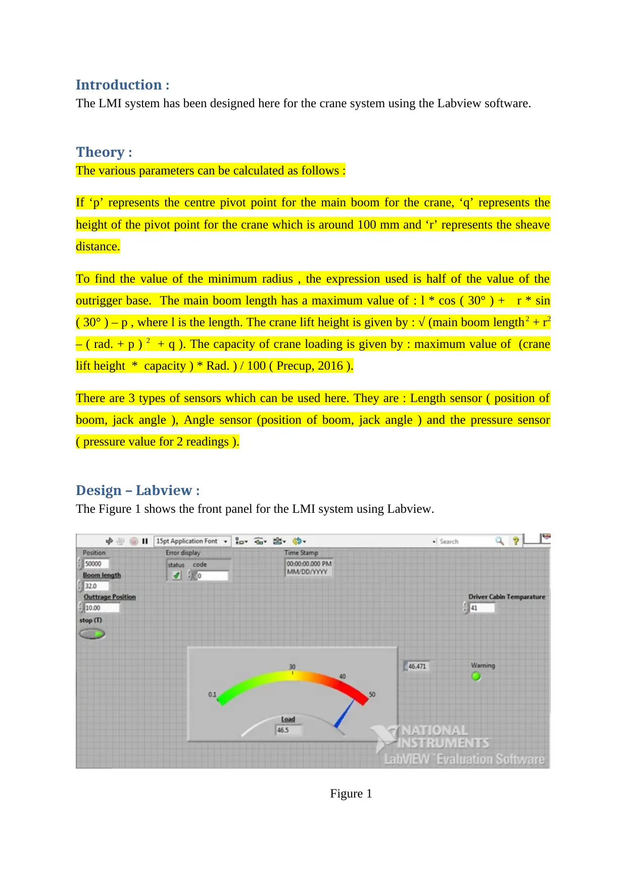
The Figure 1 shows the front panel for the LMI system using Labview.
Figure 1
⊘ This is a preview!⊘
Do you want full access?
Subscribe today to unlock all pages.

Trusted by 1+ million students worldwide
For the design of PPC ( point and position control ) in Labview, the toolbox used is the NI
Vision Picture preparation Toolbox. The data is obtained continuously by the pictures of the
various points and positions of the trolley and the truck. The design of the controller can be
obtained by design of the model for the crane in Labview.
The controller can help in switching between the 2 modes : Mounted sensor and webcam
sensing. The position of the truck can be determined by the help of the controller and the
slider. The front panel shows the various aspects.
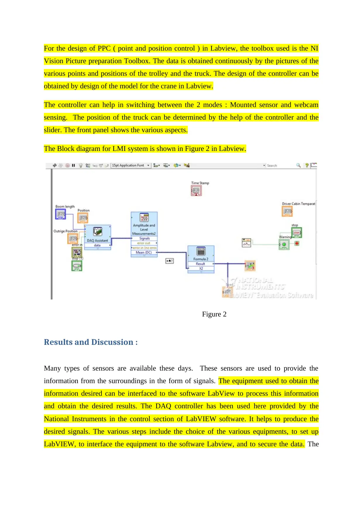
The Block diagram for LMI system is shown in Figure 2 in Labview.
Figure 2
Results and Discussion :
Many types of sensors are available these days. These sensors are used to provide the
information from the surroundings in the form of signals. The equipment used to obtain the
information desired can be interfaced to the software LabView to process this information
and obtain the desired results. The DAQ controller has been used here provided by the
National Instruments in the control section of LabVIEW software. It helps to produce the
desired signals. The various steps include the choice of the various equipments, to set up
LabVIEW, to interface the equipment to the software Labview, and to secure the data. The
Paraphrase This Document
Need a fresh take? Get an instant paraphrase of this document with our AI Paraphraser
Labview trigger is designed and the information is collected, the data is read and the
communication with the external equipment is done by using the drivers ( Lijuan, 2012 ).
The card used to secure the data is PXI-6733 ( from NI organization ). The programming
module used is the DAQmx.
The shaft pin provides an output which is given to the software by proper interfacing
( Kumar, 2013 ). The data is critically examined to get good results.
Evaluation :
If a strain is encountered, the sensors used to measure the strain value are acted upon by the
load cells for pressure. The load cell for the pressure pulls and then extends which was earlier
in a compact state. The elastic as well as the load for pulling can be measured by using the
load cells. Hence, their use is very significant in the cranes as well as for low weight
equipment. Presently, the equipment used consists of the clasp sensor, load cells of s – type,
pressure joints and the burden shackle.
A clamp sensor ( like the DLWS ) can be connected successfully to the ropes of the crane
wire. The heap can be successfully measured using it with no effect on the value of the crane
administrator’s headroom. If an over burden condition is encountered, the burden cell works
good. A light can be connected to the actuator, the lift work can be stopped and a warning can
be given by the use of the amplification by burden cell output.
The load cells used to interface strain are like CTL2 and DCL10. They are attached to the
crane’s snare. The cells are used to connect the item which needs to be estimated with the
shackle. They are a type of burden cell used to lift and gauge the applications in critical
scenarios. Such applications have a higher accuracy level as compared to the other methods
like the shackle load cell. As the gathering of the heap cell expands, it helps to complete any
headroom which is lost as the design is very easy and simple. This may range from 1 to a few
feet long. It can be represented over the connection and also using a pointer. They can be
accessed by the remote capacity and help to make the system more flexible and efficient.
Proposal :
With the help of a low cost controller, the overall cost of the system can be reduced. A low
cost controller which is also efficient needs to be incorporated for performance enhancement.
Using different media for transmission of data , the design can be improved in the future. The
latest technology involves the use of wireless media and IoT ( Internet of Things) ( Ogras,
2013 ). By the help of IoT , the various electronic and mechanical devices can be connected
to each other by the help of internet ( Aslam, 2020 ) ( Sabih, 2013 ). Each device acts as a
node which is connected to all other devices. The data can be transmitted between the devices
effectively and communication can be established by the help of Internet ( Levine, 2012 ).
This makes the system very easy to design.
References :
Precup, R.E., Preitl, S., Bojan-Dragos, C.A., Radac, M.B., Szedlak-Stinean, A.I., Hedrea,
E.L. and Roman, R.C., 2016. Evolving Takagi-Sugeno fuzzy modeling applications of
incremental online identification algorithms. In Proc. XIII InternationalSA UM Conference
on Systems, Automatic Control and Measurements (pp. 3-10).
Aslam, M.S., Dai, X., Hou, J., Li, Q., Ullah, R., Ni, Z. and Liu, Y., 2020. Reliable control
design for composite‐driven scheme based on delay networked T‐S fuzzy
system. International Journal of Robust and Nonlinear Control, 30(4), pp.1622-1642.
Levine, S.E., Bida, T.A., Chylek, T., Collins, P.L., DeGroff, W.T., Dunham, E.W., Lotz, P.J.,
Venetiou, A.J. and Kermani, S.Z., 2012, September. Status and performance of the Discovery
Channel Telescope during commissioning. In Ground-based and Airborne Telescopes
IV (Vol. 8444, p. 844419). International Society for Optics and Photonics.
Lijuan, X.X.L.H.X. and Lianhui, Y., 2012. High precision periodic control method of control
moment gyro gimbal system. Journal of Beijing University of Aeronautics and Astronautics,
(8), p.8.
Kumar, R., 2013. Efficient active vibration control of smart structures with modified positive
position feedback control using pattern search methods in the presence of instrumentation
phase lead and lag. Journal of Dynamic Systems, Measurement, and Control, 135(6).
Sabih, M., 2013. Control algorithms for distributed networked industrial systems (Doctoral
dissertation, King Fahd University of Petroleum and Minerals (Saudi Arabia)).
Ogras, H. and Türk, M., 2013. Utilizing Simulink and MATLAB graphical user interface in
modelling and simulation of chaos-based digital modulation techniques. International Journal
of Electrical Engineering Education, 50(1), p.19.
⊘ This is a preview!⊘
Do you want full access?
Subscribe today to unlock all pages.

Trusted by 1+ million students worldwide
1 out of 6
Related Documents
Your All-in-One AI-Powered Toolkit for Academic Success.
+13062052269
info@desklib.com
Available 24*7 on WhatsApp / Email
![[object Object]](/_next/static/media/star-bottom.7253800d.svg)
Unlock your academic potential
Copyright © 2020–2026 A2Z Services. All Rights Reserved. Developed and managed by ZUCOL.


