Edith Cowan University: Mining Drill Head Gearbox Design Project
VerifiedAdded on 2023/01/16
|13
|999
|48
Project
AI Summary
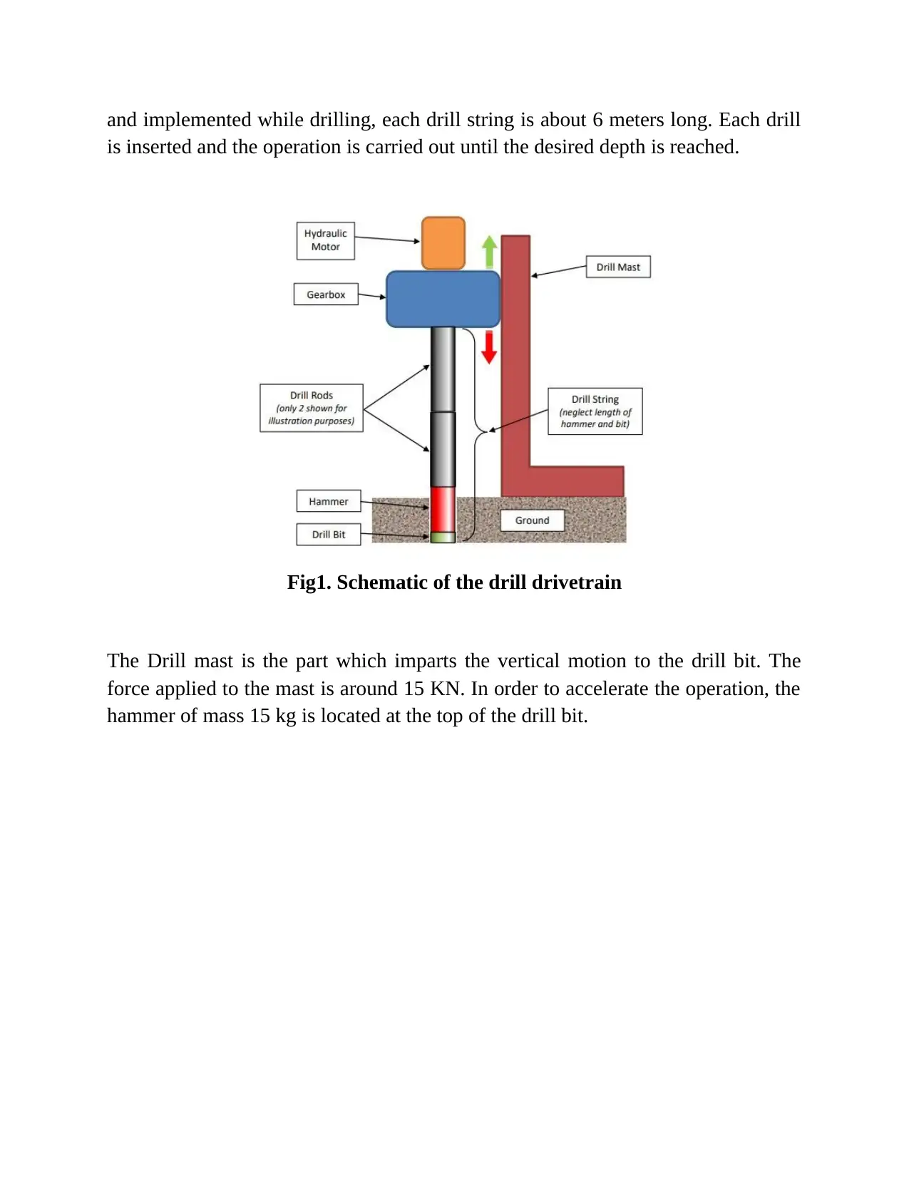
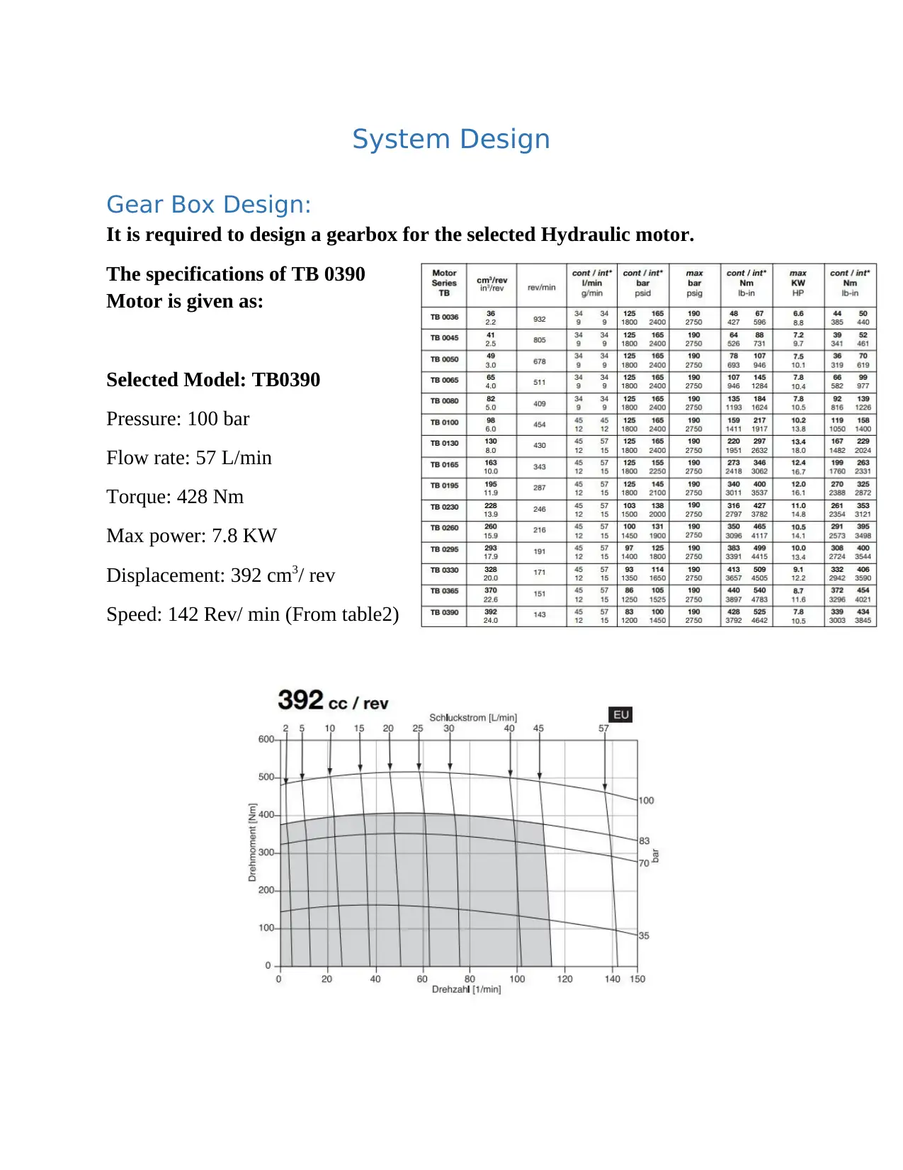
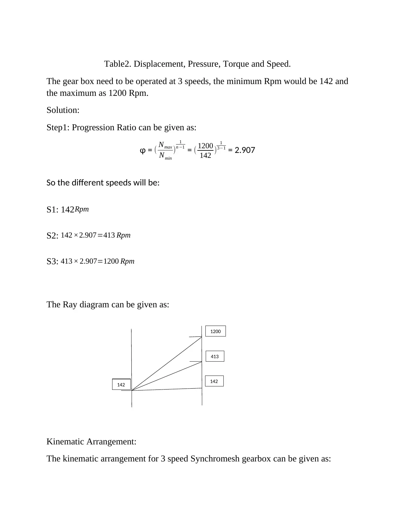
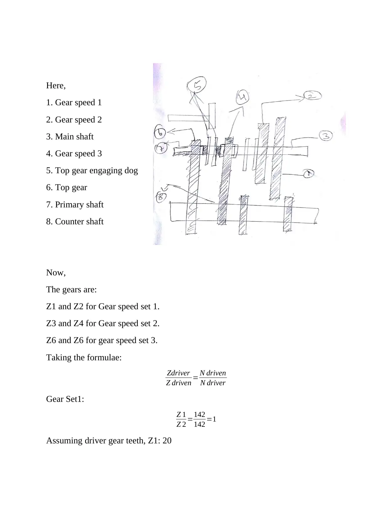
This assignment details the design of a gearbox assembly for a mining drill head, a project undertaken for an Advanced Mechanical Design course at Edith Cowan University. The design incorporates a hydraulic motor (TB0390) to drive a drill string, focusing on achieving specific performance and operational requirements. The project encompasses a product design specification, gear ratio calculations, gearbox design, gear selection, load calculations, shaft design, fastener selection, and bearing selection. The solution includes considerations for the working environment, maintenance, and a detailed breakdown of the system's components, such as the drill string, hammer, and drill teeth. The design also considers the selection of gears and their speeds, and the calculation of the progression ratio to achieve the desired speed variations. The assignment provides a comprehensive approach to the design, from initial specifications to detailed component selection and calculations.

ADVANCED MECHANICAL DESIGN
Major Assignment
Mining Drill Head Gearbox Design
Done By:
Major Assignment
Mining Drill Head Gearbox Design
Done By:
Paraphrase This Document
Need a fresh take? Get an instant paraphrase of this document with our AI Paraphraser

Contents
Assignment Requirement:...........................................................................................................................3
Segments to be covered in the Assignment:...............................................................................................3
System Details:............................................................................................................................................5
Drill string:...............................................................................................................................................5
Hammer:..................................................................................................................................................6
Drill teeth:................................................................................................................................................6
Hydraulic Motor:.....................................................................................................................................6
Design Requirement:...............................................................................................................................7
Product Design Specification:......................................................................................................................7
Performance requirements:....................................................................................................................7
Operation Requirements:........................................................................................................................7
Working Environment:............................................................................................................................8
Maintenance:..........................................................................................................................................8
Gear Ratio Calculation:................................................................................................................................8

⊘ This is a preview!⊘
Do you want full access?
Subscribe today to unlock all pages.

Trusted by 1+ million students worldwide

Assignment Requirement:
To design an entire Gearbox Assembly for mining drill head. The Gearbox
assembly is mounted on Drill rig mast and drives a drill string. The power to the
Gearbox is from a hydraulic motor. The motor torque and speed are controlled
with the help of the Gearbox and then allowed to transmit through the Drill string
to the Drillbit.
Segments to be covered in the Assignment:
1. Product Design Specification
2. Gear Ratio Calculation
3. Gear Box Design
4. Selection of Number of Gears
5. Design of Gears
6. Load Calculation
7. Shaft Design
8. Faster selection
9. Bearing Selection
The overall gearbox design is required, the gearbox comprises of various kinds of
gears, bearings, shafts, fasteners, etc. Initially, a detailed product design
specification will be created with which the product will be developed further. The
gearbox design will be carried out after finding the gear ratio requirements.
The Schematic of drill drivetrain is given as:
The below image illustrates the various parts and the power transmission line of
the drill operation. The power flows from the hydraulic motor to the Gearbox then
the modified power flows to the drill rods and reaches the drill bit.
The drill string is the part which is used to increase the depth of the mining hole.
To drill deep hole very long drill string is required but practically carrying the long
string is difficult so that the drill strings are to be connected as a separate assembly
Paraphrase This Document
Need a fresh take? Get an instant paraphrase of this document with our AI Paraphraser

and implemented while drilling, each drill string is about 6 meters long. Each drill
is inserted and the operation is carried out until the desired depth is reached.
Fig1. Schematic of the drill drivetrain
The Drill mast is the part which imparts the vertical motion to the drill bit. The
force applied to the mast is around 15 KN. In order to accelerate the operation, the
hammer of mass 15 kg is located at the top of the drill bit.

Fig2. Illustrates Mining drill operation.
System Details:
Drill string:
Length of the Drill string: 6m each
The diameter of the Drill string:
OD: 120mm
ID: 110mm
The thickness of the Drill string: 10 mm
Capacity to drill a hole up to 500 m depth.
System Details:
Drill string:
Length of the Drill string: 6m each
The diameter of the Drill string:
OD: 120mm
ID: 110mm
The thickness of the Drill string: 10 mm
Capacity to drill a hole up to 500 m depth.
⊘ This is a preview!⊘
Do you want full access?
Subscribe today to unlock all pages.

Trusted by 1+ million students worldwide

Fig2. Illustrates real drill strings
Hammer:
Mass of Hammer: 15 Kg
The frequency with which hammer oscillated: 15 Hz
Amplitude: 100 mm
Drill teeth:
Coefficient of friction between drill teeth and surface: 0.5
Hammer:
Mass of Hammer: 15 Kg
The frequency with which hammer oscillated: 15 Hz
Amplitude: 100 mm
Drill teeth:
Coefficient of friction between drill teeth and surface: 0.5
Paraphrase This Document
Need a fresh take? Get an instant paraphrase of this document with our AI Paraphraser

Fig3. Illustrates Drill bit teeth.
Design Requirement:
Service Life of 10,000 Hours.
Design for Manufacturing
High Reliability
Product Design Specification:
Performance requirements:
High Torque
High Speed
Nonstop operation
Constant cooling necessary
Capacity to provide enough torque to drill 500 m depth hole.
Design Requirement:
Service Life of 10,000 Hours.
Design for Manufacturing
High Reliability
Product Design Specification:
Performance requirements:
High Torque
High Speed
Nonstop operation
Constant cooling necessary
Capacity to provide enough torque to drill 500 m depth hole.

Operation Requirements:
Reliability
High power
Service life up to 10,000 hrs
Working Environment:
Hard working conditions
Above 400 C temperature.
Sand and dust particles.
Unclean and smoky environment.
Maintenance:
Designed for easy service.
Design for easy repair operations.
Design for easy cleaning.
No direct opening to the inside of the gearbox.
Completely covered gearbox.
⊘ This is a preview!⊘
Do you want full access?
Subscribe today to unlock all pages.

Trusted by 1+ million students worldwide

System Design
Gear Box Design:
It is required to design a gearbox for the selected Hydraulic motor.
The specifications of TB 0390
Motor is given as:
Selected Model: TB0390
Pressure: 100 bar
Flow rate: 57 L/min
Torque: 428 Nm
Max power: 7.8 KW
Displacement: 392 cm3/ rev
Speed: 142 Rev/ min (From table2)
Gear Box Design:
It is required to design a gearbox for the selected Hydraulic motor.
The specifications of TB 0390
Motor is given as:
Selected Model: TB0390
Pressure: 100 bar
Flow rate: 57 L/min
Torque: 428 Nm
Max power: 7.8 KW
Displacement: 392 cm3/ rev
Speed: 142 Rev/ min (From table2)
Paraphrase This Document
Need a fresh take? Get an instant paraphrase of this document with our AI Paraphraser

Table2. Displacement, Pressure, Torque and Speed.
The gear box need to be operated at 3 speeds, the minimum Rpm would be 142 and
the maximum as 1200 Rpm.
Solution:
Step1: Progression Ratio can be given as:
ɸ = ( Nmax
Nmin
)
1
n −1 = ( 1200
142 )
1
3−1 = 2.907
So the different speeds will be:
S1: 142Rpm
S2: 142 ×2.907=413 Rpm
S3: 413 × 2.907=1200 Rpm
The Ray diagram can be given as:
Kinematic Arrangement:
The kinematic arrangement for 3 speed Synchromesh gearbox can be given as:
142
413
1200
142

Here,
1. Gear speed 1
2. Gear speed 2
3. Main shaft
4. Gear speed 3
5. Top gear engaging dog
6. Top gear
7. Primary shaft
8. Counter shaft
Now,
The gears are:
Z1 and Z2 for Gear speed set 1.
Z3 and Z4 for Gear speed set 2.
Z6 and Z6 for gear speed set 3.
Taking the formulae:
Zdriver
Z driven = N driven
N driver
Gear Set1:
Z 1
Z 2 =142
142 =1
Assuming driver gear teeth, Z1: 20
⊘ This is a preview!⊘
Do you want full access?
Subscribe today to unlock all pages.

Trusted by 1+ million students worldwide
1 out of 13

Your All-in-One AI-Powered Toolkit for Academic Success.
+13062052269
info@desklib.com
Available 24*7 on WhatsApp / Email
Unlock your academic potential
Copyright © 2020–2025 A2Z Services. All Rights Reserved. Developed and managed by ZUCOL.