Mechanical Engineering Design 36: Electric Bike Project
VerifiedAdded on 2022/10/01
|44
|6476
|123
Project
AI Summary
This project details the design of an electric bike, emphasizing environmental conservation through the use of electrical energy. The project encompasses both conceptual and final design phases, leveraging CAD, FMEA, and ANSYS simulation software for structural analysis. The report includes a comprehensive overview of the design process, from initial conceptualization to the selection of key components like the frame, motor, battery, and brakes. It details the use of SolidWorks for 3D modeling and ANSYS for finite element analysis (FEA) to assess the structural integrity of the design under various conditions. The project also incorporates Design for Assembly (DFA), Design for Environment (DFE), and Design for Disassembly (DFD) considerations, along with a Failure Mode and Effect Analysis (FMEA) to ensure safety and reliability. The final design is presented with recommendations and conclusions, highlighting the project's focus on creating an efficient and environmentally friendly mode of transportation. The design also includes Gantt chart, tables and figures illustrating the project's progress and findings.
Mechanical engineering design 1
MECHANICAL ENGINEERING DESIGN
By Name
Course
Instructor
Institution
Location
Date
MECHANICAL ENGINEERING DESIGN
By Name
Course
Instructor
Institution
Location
Date
Paraphrase This Document
Need a fresh take? Get an instant paraphrase of this document with our AI Paraphraser
Mechanical engineering design 2
EXERCUTIVE SUMMARY
This project is addressing the design of an electric bike which will be to operate
exclusively on the motor and battery (electrical energy). Therefore the proposed designed of the
electric bike will help in conserving the environment since there is no emission of carbon (IV)
oxide. There will be the use of some analysis software where the simulation will be done to
check if the structure of the electric bike can really work in the real design. Some of these
simulation software includes the CAD, FMEA, among other software. This project has
conceptual design and the final design. The conceptual design is the process of coming up with
idea of the project while the final design is where the actual design of the electric bike is done.
Mechanical engineering design 3
TABLE OF CONTENT
EXERCUTIVE SUMMARY...............................................................................................................................2
TABLE OF CONTENT...............................................................................................................................3
TABLE OF FIGURES................................................................................................................................5
LISTS OF TABLES....................................................................................................................................5
INTRODUCTION.......................................................................................................................................6
AIMS AND OBJECTIVES.........................................................................................................................7
Aims of the project..................................................................................................................................7
Objectives of the project..........................................................................................................................7
TEAM ACTIVITY......................................................................................................................................7
Member Roles.........................................................................................................................................8
GANTT CHART.......................................................................................................................................10
CONCEPTUAL DESIGN.........................................................................................................................11
Regal requirement.................................................................................................................................11
The design conception...........................................................................................................................12
Frame design.........................................................................................................................................14
Electronic bike Wheel (rear and bake)...................................................................................................15
Motor & Control....................................................................................................................................16
Battery...................................................................................................................................................17
Drive Train and the Hub........................................................................................................................19
Brakes....................................................................................................................................................20
Handle...................................................................................................................................................21
FINAL DESIGN........................................................................................................................................22
IMPORTANT SELECTIONS...................................................................................................................25
Safety Requirement for electric bike.....................................................................................................26
Component selection of this design.......................................................................................................28
Wheels...............................................................................................................................................28
Brakes................................................................................................................................................28
ANSYS ANALYSIS.................................................................................................................................28
Design for Assembly (DFA)..................................................................................................................29
Design for Environment (DFE).............................................................................................................29
Design for Disassembly (DFD).............................................................................................................30
⊘ This is a preview!⊘
Do you want full access?
Subscribe today to unlock all pages.
Trusted by 1+ million students worldwide
Mechanical engineering design 4
Failure Mode and Effect Analysis (FMEA)...........................................................................................30
Simulation Results.....................................................................................................................................32
Final Product.........................................................................................................................................35
RECOMMENDATIONS...........................................................................................................................36
CONCLUSION.........................................................................................................................................36
REFERENCES..........................................................................................................................................37
APPENDIX...............................................................................................................................................40
Paraphrase This Document
Need a fresh take? Get an instant paraphrase of this document with our AI Paraphraser
Mechanical engineering design 5
TABLE OF FIGURES
Figure 1: Showing the Gantt chart.................................................................................................10
Figure 2: Showing the first conceptual design of the e bike..........................................................11
Figure 3: Showing the second conceptual design of the project...................................................12
Figure 4: Showing the frame part of the e bike.............................................................................13
Figure 5: Showing the real and back wheels of the e-bike............................................................15
Figure 6: Showing the brushless motor installed in the wheel of the electric bike.......................16
Figure 7: Showing selected lithium battery used in the operation of the electric bike..................16
Figure 8: Showing the assembly of sprocket, hub and drive train of the electric bike..................18
Figure 9: Showing the brake of the e bike.....................................................................................19
Figure 10: Showing the handle of e bike.......................................................................................20
Figure 11: Showing Boundary conditions defined for the FEA simulation..................................21
Figure 12: Showing equivalent vonmess stress contour................................................................21
Figure 13: Showing a total deformation........................................................................................22
Figure 14: Showing Equivalent stress contours.............................................................................23
Figure 15: Showing Total deformation Contours..........................................................................23
Figure 16: Showing e bike helmet.................................................................................................26
Figure 17: Showing the e bike reflector jackets............................................................................26
Figure 18: Showing results for normalstress aluminium...............................................................31
Figure 19: Showing results for normalstress steel.........................................................................31
Figure 20: Showing results in normalstress titanium....................................................................32
Figure 21: Showing total deformation for aluminum....................................................................32
Figure 22: Showing total deformation for aluminum....................................................................33
Figure 23: Showing total deformation for titanium.......................................................................33
Figure 24: Showing boundary.......................................................................................................34
Figure 25: Showing final product after the design........................................................................34
LISTS OF TABLES
Table 1: Showing group members and their ID...............................................................................7
Table 2: Showing the work divided Into terms of researching........................................................7
Table 3: Showing the work divided In terms of CAD.....................................................................8
Table 4: Showing the work divided Into terms of analysis.............................................................8
Table 5: Overall work done by every member................................................................................8
Table 6: Showing the cost analysis of this electric bike................................................................24
Table 7: Showing Failure Mode & Effect Analysis......................................................................30
Mechanical engineering design 6
INTRODUCTION
This project is mainly focusing on the designing of the electrical bike, this is very
important as it will enhance the quicker and safer movement of people within Australia as well
as other countries of the world. This report will give the design as well as the implementation of
the designed mathematical models. This is made possible with the use of the engineering
concepts that aid in realizing the aims effectively. With the higher population in most states in
Australia, public transport has always shown some traffics and this public transport uses fossils
fuels in their transportation and this really pollutes our environment.
The use of fossil motorcycles also pollutes our environment due to the combustion of
fossil fuels. It is hence very significant to have a way of transportation which will reduce the
traffics on the road and also reduce the pollution of our environment. This project gives the real
design of the e-bike which starts from the conceptual point design to the final design which will
be employed to give the real design that will be implemented to the actual e bike. During the
design of this e-bike there are some software which will be employed to make the design
perfectly without making some errors in the final design. Some of this software include the
DFD, CAD, DFX, and FMEA.
BACKGROUND
The use of electric bike is becoming common in most parts of Australia and the whole world.
These bike are always designed and constructed with the consideration of the strength, aesthetical
values, light weight as well as making the bike to be affordable for most people. Some of the pioneers
who came up with idea of bicycle include William Ayrton and John Perry around 1880s. The increasing
⊘ This is a preview!⊘
Do you want full access?
Subscribe today to unlock all pages.
Trusted by 1+ million students worldwide
Mechanical engineering design 7
number of e bike in the market is due to the advantages of its being environmentally friendly.
These bikes are today playing a big role in the transportation industry because they are relatively
cheap, they are easier to operate, and they also have low maintenance as well as the
convertibility. Therefore the convertibility of this type of bike offers the society the chance to
use e bike with higher satisfaction.
The popularity of this type of bike is chiefly due to the effects which it gives to the
operators like the cost benefits and the health importance. And because these bikes do not use
fossil fuels which are relatively expensive as compared to the use of electricity, the operation and
maintenance of the e bike become cheaper than the fossil automotive. Therefore for these
reasons and benefits of the e bike, this bike is hence very crucial in the transportation industry.
Electric bike makes transportation easier the fuel used here is relatively cheaper and more
environmental friendly. As opposed to the cycled bikes , the electric bike moves at a very higher
speed and also can operate in hilly without applying effort by the rider hence this makes it easier
and more comfortable to use.
AIMS AND OBJECTIVES
Aims of the project
The project aim of this project is to study and design the e bike using the solidWorks as well as
the use of the ANSYS workbench software.
Paraphrase This Document
Need a fresh take? Get an instant paraphrase of this document with our AI Paraphraser
Mechanical engineering design 8
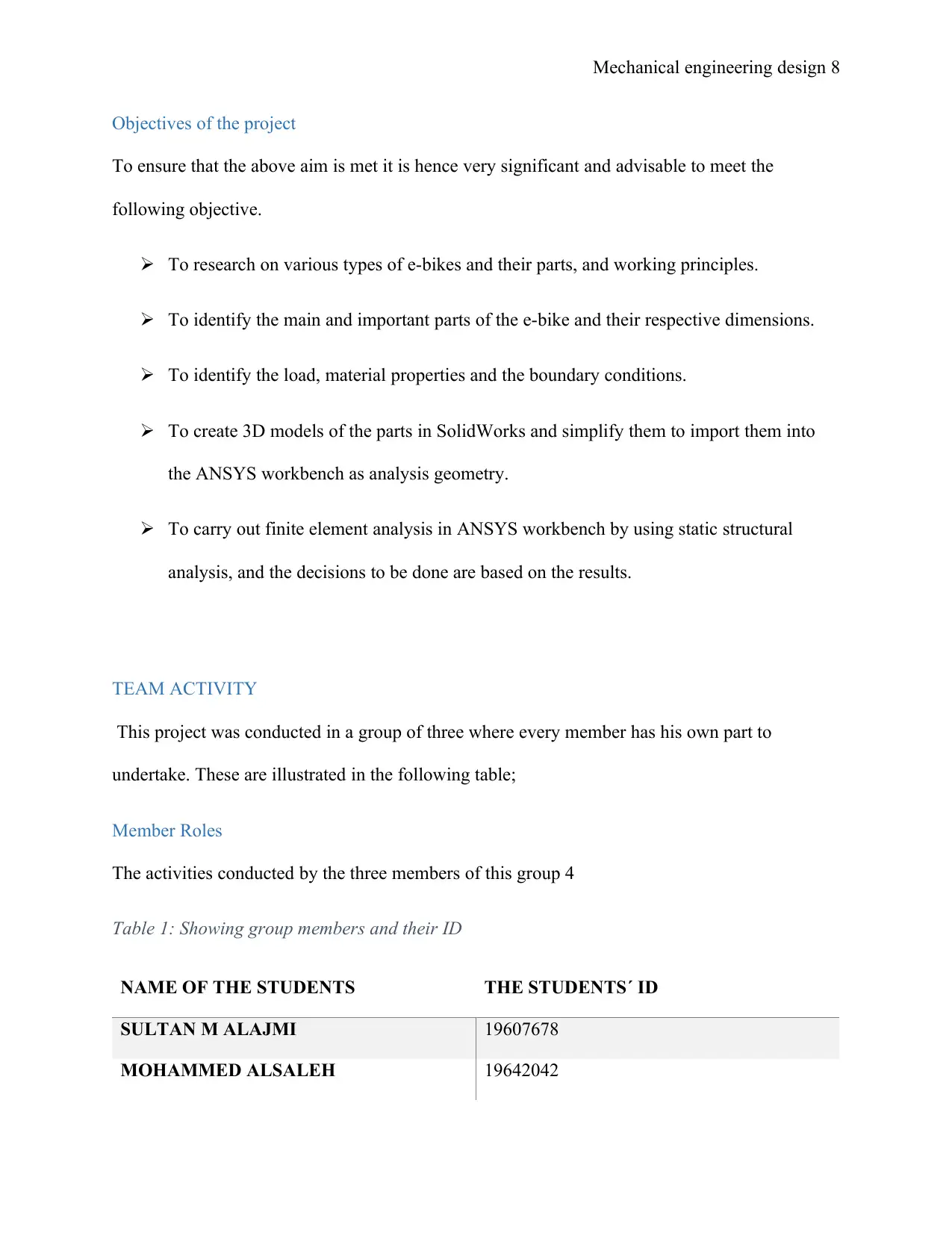
Objectives of the project
To ensure that the above aim is met it is hence very significant and advisable to meet the
following objective.
To research on various types of e-bikes and their parts, and working principles.
To identify the main and important parts of the e-bike and their respective dimensions.
To identify the load, material properties and the boundary conditions.
To create 3D models of the parts in SolidWorks and simplify them to import them into
the ANSYS workbench as analysis geometry.
To carry out finite element analysis in ANSYS workbench by using static structural
analysis, and the decisions to be done are based on the results.
TEAM ACTIVITY
This project was conducted in a group of three where every member has his own part to
undertake. These are illustrated in the following table;
Member Roles
The activities conducted by the three members of this group 4
Table 1: Showing group members and their ID
NAME OF THE STUDENTS THE STUDENTS´ ID
SULTAN M ALAJMI 19607678
MOHAMMED ALSALEH 19642042
Mechanical engineering design 9
MOUHAMAD GHUNEIM 19811680
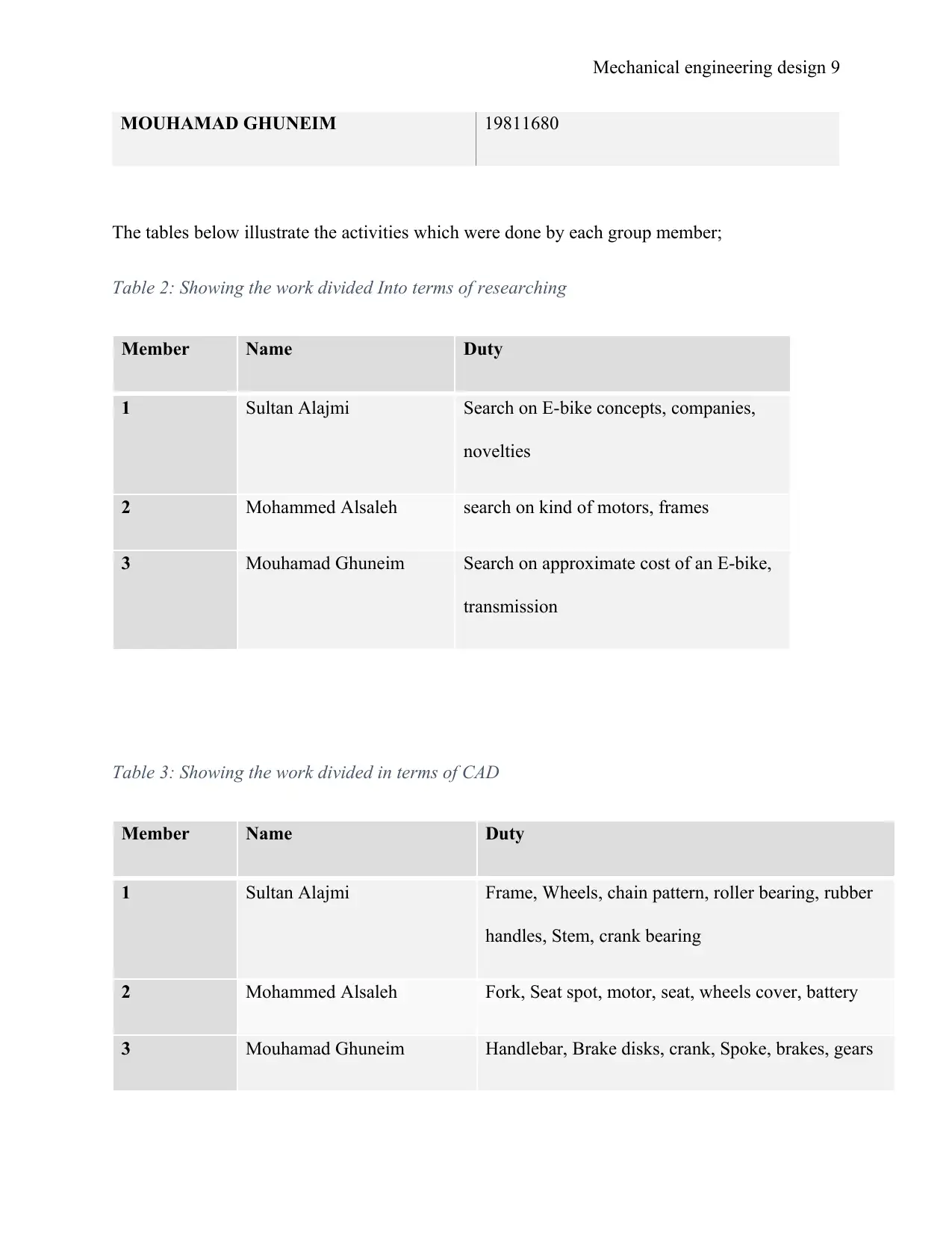
The tables below illustrate the activities which were done by each group member;
Table 2: Showing the work divided Into terms of researching
Member Name Duty
1 Sultan Alajmi Search on E-bike concepts, companies,
novelties
2 Mohammed Alsaleh search on kind of motors, frames
3 Mouhamad Ghuneim Search on approximate cost of an E-bike,
transmission
Table 3: Showing the work divided in terms of CAD
Member Name Duty
1 Sultan Alajmi Frame, Wheels, chain pattern, roller bearing, rubber
handles, Stem, crank bearing
2 Mohammed Alsaleh Fork, Seat spot, motor, seat, wheels cover, battery
3 Mouhamad Ghuneim Handlebar, Brake disks, crank, Spoke, brakes, gears
MOUHAMAD GHUNEIM 19811680
The tables below illustrate the activities which were done by each group member;
Table 2: Showing the work divided Into terms of researching
Member Name Duty
1 Sultan Alajmi Search on E-bike concepts, companies,
novelties
2 Mohammed Alsaleh search on kind of motors, frames
3 Mouhamad Ghuneim Search on approximate cost of an E-bike,
transmission
Table 3: Showing the work divided in terms of CAD
Member Name Duty
1 Sultan Alajmi Frame, Wheels, chain pattern, roller bearing, rubber
handles, Stem, crank bearing
2 Mohammed Alsaleh Fork, Seat spot, motor, seat, wheels cover, battery
3 Mouhamad Ghuneim Handlebar, Brake disks, crank, Spoke, brakes, gears
⊘ This is a preview!⊘
Do you want full access?
Subscribe today to unlock all pages.
Trusted by 1+ million students worldwide
Mechanical engineering design 10
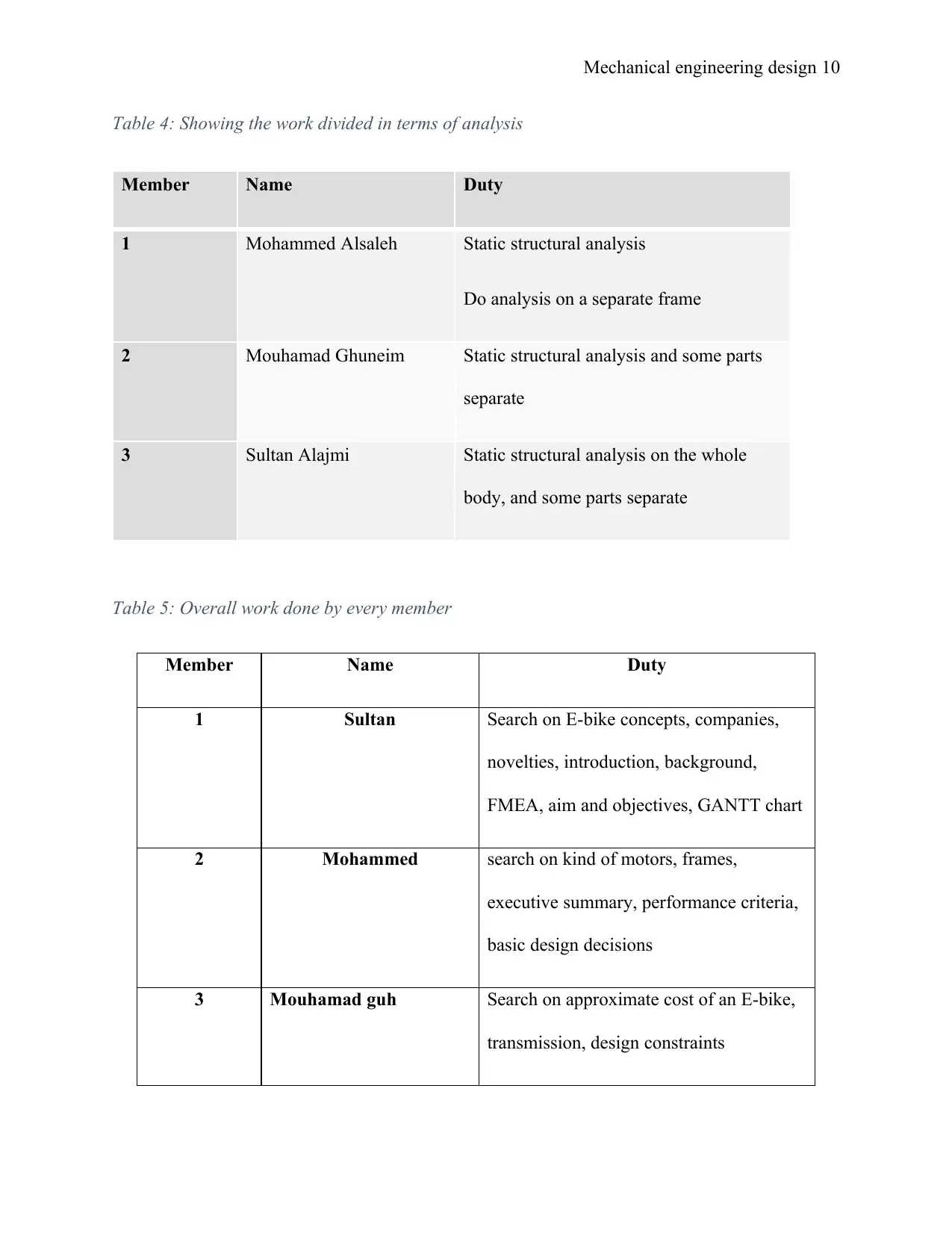
Table 4: Showing the work divided in terms of analysis
Member Name Duty
1 Mohammed Alsaleh Static structural analysis
Do analysis on a separate frame
2 Mouhamad Ghuneim Static structural analysis and some parts
separate
3 Sultan Alajmi Static structural analysis on the whole
body, and some parts separate
Table 5: Overall work done by every member
Member Name Duty
1 Sultan Search on E-bike concepts, companies,
novelties, introduction, background,
FMEA, aim and objectives, GANTT chart
2 Mohammed search on kind of motors, frames,
executive summary, performance criteria,
basic design decisions
3 Mouhamad guh Search on approximate cost of an E-bike,
transmission, design constraints
Paraphrase This Document
Need a fresh take? Get an instant paraphrase of this document with our AI Paraphraser
Mechanical engineering design 11
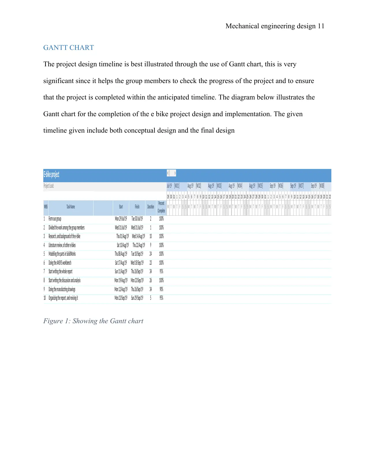
GANTT CHART
The project design timeline is best illustrated through the use of Gantt chart, this is very
significant since it helps the group members to check the progress of the project and to ensure
that the project is completed within the anticipated timeline. The diagram below illustrates the
Gantt chart for the completion of the e bike project design and implementation. The given
timeline given include both conceptual design and the final design
E-bike project ## ## ## ## ## ## ## ## ## ## ## ## ## ## ## ## ## ## ## ## ## ## ## ## ## ## ## ## ## ## ## ## ## ## ## ## ## ## ## ## ## ## ## ## ## ## ## ## ## ## ## ## ## ## ## ##
Project Lead: Jul-19 [W31] Aug-19 [W32] Aug-19 [W33] Aug-19 [W34] Aug-19 [W35] Sep-19 [W36] Sep-19 [W37] Sep-19 [W38]
29 30 31 1 2 3 4 5 6 7 8 9 10 11 12 13 14 15 16 17 18 19 20 21 22 23 24 25 26 27 28 29 30 31 1 2 3 4 5 6 7 8 9 10 11 12 13 14 15 16 17 18 19 20 21 22
WBS Task Name Start Finish Duration Percent
Complete M T W T F S S M T W T F S S M T W T F S S M T W T F S S M T W T F S S M T W T F S S M T W T F S S M T W T F S S
1 Form our group Mon 29/Jul/19 Tue 30/Jul/19 2 100%
2 Divided the work among the group members Wed 31/Jul/19 Wed 31/Jul/19 1 100%
3 Research, and background of the e-bike Thu 01/Aug/19 Wed 14/Aug/19 10 100%
4 Literature review, of other e-bikes Sat 10/Aug/19 Thu 22/Aug/19 9 100%
5 Modelling the parts in SolidWorks Thu 08/Aug/19 Tue 10/Sep/19 24 100%
6 Doing the ANSYS workbench Sat 17/Aug/19 Wed 18/Sep/19 23 100%
7 Start writing the whole report Sun 11/Aug/19 Thu 26/Sep/19 34 95%
8 Start writing the discussion and analysis Mon 19/Aug/19 Mon 23/Sep/19 26 100%
9 Doing the manufactring drawings Mon 12/Aug/19 Thu 26/Sep/19 34 90%
10 Organizing the report, and revising it Mon 23/Sep/19 Sun 29/Sep/19 5 95%
Figure 1: Showing the Gantt chart
Mechanical engineering design 12
CONCEPTUAL DESIGN
Regal requirement
As discussed above the use of e-bike to reduce the combustion of fossil have several positive
effects on our environment due to the reduction of pollution. Hence the use of the electric bike
law help in the reduction of the following issues in most country including Australia;
An electric bike needs to have a maximum power consumption of about 200kW without limit for
the bikes speed and the pedal sensors to operate effectively (Dill, 2012). The law hence helps in
promoting the use of more electric bikes to help reduce pollution. Some of the key legal aspect
of the electric bike to make them operate effectively include the following actions put forward by
the authority;
There must be a rear reflector for the reader both during the day and night just to identify
themselves as riders and also for visibility at night.
The e bike needs to have a maximum radius of illumination of the light of about 200
meters.
The back and front installed flashing light of the electric bike need to operate effectively
at night when these bikes are on the road, where the red lights are preferred at the back of
the bike.
The design conception
The idea of the design was first put on paper from where the group member could then
fathom what is required and which parts need to be designed as well as simulated. The first
concept put on paper is illustrated in the diagram below;
⊘ This is a preview!⊘
Do you want full access?
Subscribe today to unlock all pages.
Trusted by 1+ million students worldwide
1 out of 44
Related Documents


Your All-in-One AI-Powered Toolkit for Academic Success.
+13062052269
info@desklib.com
Available 24*7 on WhatsApp / Email
![[object Object]](/_next/static/media/star-bottom.7253800d.svg)
Unlock your academic potential
Copyright © 2020–2026 A2Z Services. All Rights Reserved. Developed and managed by ZUCOL.