Further Mechanical Principles: Assignment on Beam Analysis and Forces
VerifiedAdded on 2019/09/19
|3
|374
|439
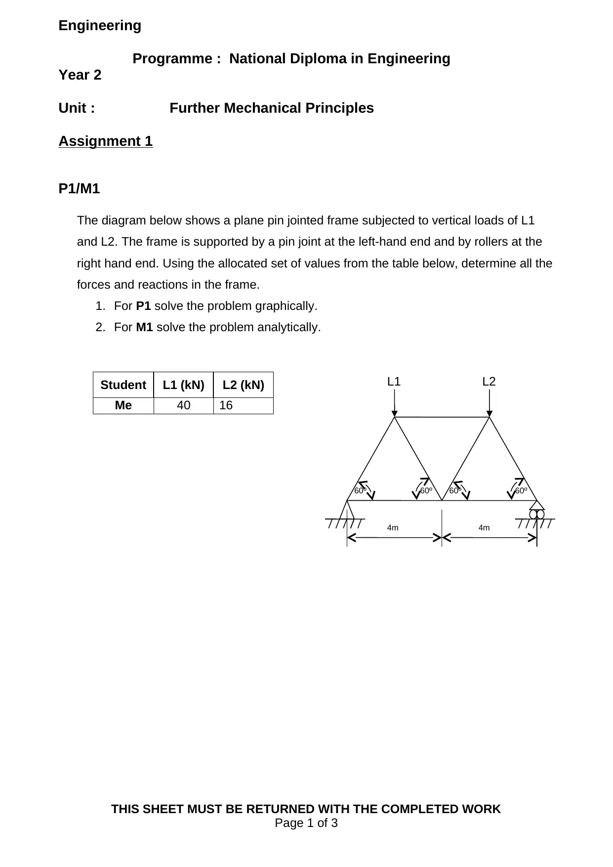
Homework Assignment
AI Summary
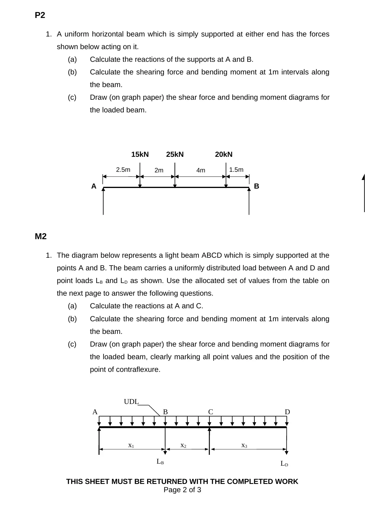
This assignment solution addresses a mechanical engineering problem focusing on beam analysis and force calculations. The assignment is divided into two main parts. The first part involves analyzing a pin-jointed frame, requiring graphical and analytical solutions to determine forces. The second part deals with the analysis of beams, including the calculation of reactions, shear forces, and bending moments at various points along the beam. Students are required to draw shear force and bending moment diagrams, and identify the point of contraflexure. Specific values for loads and dimensions are provided, enabling a comprehensive understanding of structural behavior under different loading conditions. This assignment is designed to enhance the student's understanding of fundamental engineering principles and their application in structural analysis.

1 out of 3
Related Documents


Your All-in-One AI-Powered Toolkit for Academic Success.
+13062052269
info@desklib.com
Available 24*7 on WhatsApp / Email
![[object Object]](/_next/static/media/star-bottom.7253800d.svg)
Copyright © 2020–2026 A2Z Services. All Rights Reserved. Developed and managed by ZUCOL.