Mechanical Engineering: Driveshaft, Turbine, and Flow Analysis
VerifiedAdded on 2022/09/27
|9
|1435
|26
Practical Assignment
AI Summary
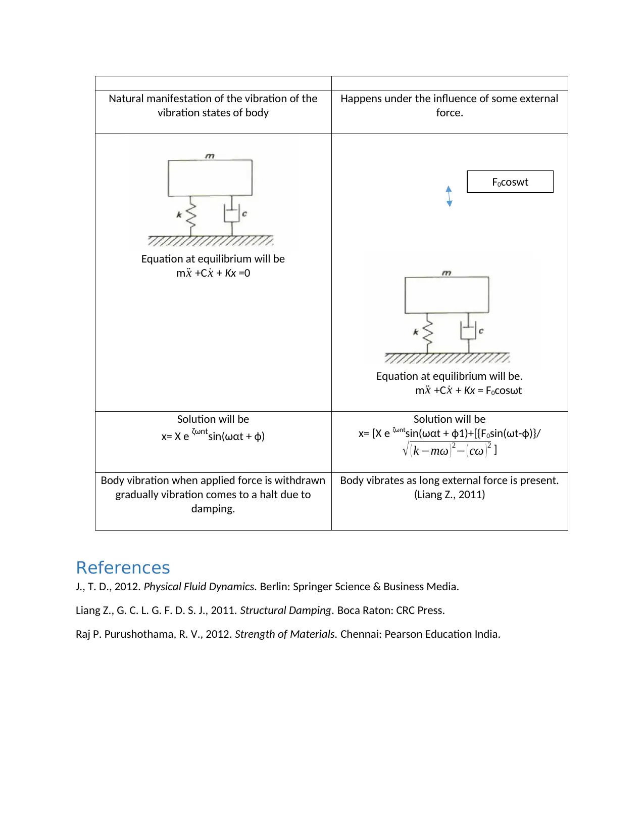
This document presents a comprehensive solution to a mechanical engineering assignment, addressing two case studies. The first case study involves the analysis of a driveshaft, including drawing an internal torque diagram, deriving an expression for the twist angle, calculating the shaft diameter based on a twist angle constraint, and determining the maximum shear stress. The second case study focuses on the efficiency analysis of a steam turbine, calculating the thermal cycle efficiency and discussing energy losses. Additionally, the assignment covers fluid dynamics, including calculations related to pipe flow, Reynolds number determination, and flow regime prediction, along with an analysis of damped vibrations including damping ratio, natural frequency, and the effects of damping, as well as the difference between free and forced damped vibration.
Contribute Materials
Your contribution can guide someone’s learning journey. Share your
documents today.

Mechanical engineering systems
[Document subtitle]
OCTOBER 9, 2019
[Document subtitle]
OCTOBER 9, 2019
Secure Best Marks with AI Grader
Need help grading? Try our AI Grader for instant feedback on your assignments.

Question1.
I. Internal torque diagram
C-d section.
Most sensitive stretch segment of the shaft
II. By torsion equation
A B C D E F
A
B C D E
F
420Nmm 240Nmm 480Nmm 300 Nmm
Internal
torque
diagram
A
B C D E
F
420Nmm 300Nmm
240Nmm
480Nmm
I. Internal torque diagram
C-d section.
Most sensitive stretch segment of the shaft
II. By torsion equation
A B C D E F
A
B C D E
F
420Nmm 240Nmm 480Nmm 300 Nmm
Internal
torque
diagram
A
B C D E
F
420Nmm 300Nmm
240Nmm
480Nmm

τ
r = T
Ip = Gɵ
l
Where τ =shear stress due to torque at radius ‘r’ from centroidal axis
ɵ = angle of twist
l = length of each segment
Ip = polar moment of inertia
G = shear modulas or modulas of rigidity
Gɵ
l = T
Ip
ɵ= Tl
GIp
III. let DB , C, D, E = dia of shaft B, C, D, E
∑Max = 3.5° = π
180 x 3.5 = 0.061
ɵB= ( TBlB) / (GIpB)
Ip = (π/32) (DB)4
ɵB= (32 TBlB) / (GπDB4)
ɵB = (32x420 x 500)/(9000 x π x 0.061 x 10) = 389.62522
DB = 4.4428 mm
DC =4
√ 32 X 240 X 500
90000 X π X 0.061 = 3.8628 mm
DC =4
√ 32 X 480 X 500
90000 X π X 0.061 = 4.5937 mm
DC =4
√ 32 X 300 X 500
90000 X π X 0.061 = 4.0844 mm
IV. τ= (Tr)/Ip
RB = 2.2214 mm, TB = 420 Nmm (CW)
Rc = 1.9314 mm, Tc = 240 Nmm (CCW)
RD = 2.2968 mm, TD = 480 Nmm (CCW)
RE = 2.0422 mm, TE = 300 Nmm (CW)

IPB = (π/32) X (Dp)4 = (π/32) X (4.4428)4 = 38.25 mm4
IPC = 21.86 mm4
IPD = 43.72 mm4
IPE = 27.322 mm4
τb= (TBrB)/IpB
=(420 X 2.2214)/38.25 = 24.39 MPa
ΤC= (240 X 1.9314)/21.86 = 21.21 MPa
τD= (480X 2.2968)/43.72 = 25.22 MPa
τE= (300 X 2.0422)/27.322 = 22.42 MPa
τmax= τD = 25.22 MPa (Raj P. Purushothama, 2012)
Question 2
Work done by turbine ‘W’ = 50MW
Heat supplied = Qs = 150 MW
I. Ƞcycle = Net work done / Total heat supplied = Wnet/Qs
Wnet = W = 50 MW
Ƞcycle = (50/150) X 100%
Ƞcycle = 33.33%
The remaining energy is spent inform of loses which are mention below:
1. Losses due to leakage of steam through seals, glands, nozzles space between moving blades.
2. Losses due to friction in nozzles. The energy is lost by steam before entering the nozzles,
frictional resistance in nozzle walls, friction between steam modules, deflection of the
below.
3. Blades friction losses due to rough surface, eddies formation.
4. Leakage of steam through labyrinth glands results in energy loss from stem.
5. Residual velocity loss due to whirl component.
6. Extend losses which includes bearing friction, sealing etc.
II. D1, D2 & D3 are the diameter of three commercial pipes
Friction coefficient ‘f’ = 0.05
D1 = 35 inch = 88.9 cm = 0.889m
D2 = 40 inch = 101.6cm = 1.016m
D3 = 50 inch = 127 cm = 1.27m
Height ‘h’ = 6m
Secure Best Marks with AI Grader
Need help grading? Try our AI Grader for instant feedback on your assignments.

Considering pipe 1:
Velocity of fluid in pipe = √ 2 gh
V=√2 X 9.81 X 6 = 117.72 ms-1
Head loses due to friction
hf1 = (4f’LV2)/2gD1
Hf1 = (4x0.05xLx117.722)/(2x9.81x0.889) = 158.902L
Considering pipe2:
hf2 = (4f’LV2)/2gD2 = 4x0.05x117.722/2x9.81x1.016 = 111.231L
Considering pipe3:
hf3 = (4f’LV2)/2gD3 = 4x0.05xLx117.712/2x9.81x1.27 = 111.231L
Head loss due to friction is considered to be major loss and since hf3 is lower than hf1 & hf2 so pipe three
must be considering for design.
iii. Reynolds number Re = ρVL
μ
V = velocity
μ=¿ Viscosity of water
L = characteristic length
μ=¿ 8.90 X 10⁻⁴ Pas at 25°C
V = 500 cms-1
L = 4 X Area
perimeter = 4 X 50 X 30 X 10−6
2 ( 50+30 ) X 10−3
I = 1000 X 5 X 0.0375
8.90 X 10−4 = 0.0375 m
Re = ρVL
μ = 2 X 50 X 30 X 10−3
8.90 X 10− 4 = 2106741573
Since Re > 4000 therefore flow is turbulent is the duct.
iv. Reynolds number is used to predict the flow pattern in different flow situation. Lower Reynolds
number depicts laminar flow and higher Re depicts turbulent flow. In otherwords Re is important in
predicting the behavior of fluid on larger scale.
For a fluid flow in a pipe:

If Re< 2000 than the flow is laminar
if Re> 4000 than the flow is turbulent.
If Re lies in between 2000 and 4000 than the flow can’t be purely laminar or turbulent.
Proof that Reynolds number is dimension less quantity:
Reynolds number = (velocity X density X diameter) / Viscosity
Velocity = [LT-1]
Density = [ML-3]
Diameter = [L]
Viscosity = [ML-1T-1]
Re = [ ¿−1][ML−3][L]
[ML−1 T −1] = [M0L0T0] (J., 2012)
Question: 3
i. M = 35g = 0.035 Kg
K = 10 Nm-1
C= 0.003Nsm-1
Damping ratio = (Actual damping coefficient)/(critical damping coefficient)
Damping ratio = C/2
√ Km = = 0.003/ 2
√ 10 X 0.035 = 2.54 X 10⁻³
Damped natural frequency ωd = ωn√1−(damping ratio)2
ωn=
√ K
m = √ 10
0.035 =16.9 Hz
ωd=16.9 √1−(2.54 x 10⁻³)2
=16.899Hz
Sketch of natural vibration
Equation of equilibrium
m
δx m ¨x m ˙x

ii. m ¨x +C ˙x + sx = 0
from fig
m ¨x +C ˙x + Kx = 0
¨x +C ˙x /m + Kx/m= 0
¨x +C ˙x /m +w2x= 0
Where
w2 = k/m
D2 + (c/m)D + w2 = 0
Second order differential equation
Solution of above equation will be
x= Xe-αt
α1, α2 =( -(c/m) ± √ ( c
m )
2
−4 w2 )/2
so α1, α2 =( -(c/2m) ± √ ( c
2 m )2
−w2 )/2
A. For roots to be real / distinct therefore it is critical damping
Let the discriminant to be zero
( C
2m )2 – w2 = 0
C
2m =w
Cc = 2mw
Cc = critical damping coefficient
B. For roots to be real and equal
X(t) = (A+Bt)e-αt
m
Kx m ¨x m ˙x
Paraphrase This Document
Need a fresh take? Get an instant paraphrase of this document with our AI Paraphraser

α = (Cc) /2m
X(t) = (A+Bt)e-(Cc/2m)t
A, B based on initial condition. Response decays exponentially
Discriminant ≠ 0 i.e D ≠0
Case1. Let discriminant is negative
( C
2m )2–w2 < 0
Therefore, system is under damped system
C < Cc
D = ( C
2m )2 –w2
D = ( C
2m )^2 –4w2
D = -(4w2 - ( C
m )2
D = i2[(4w2 - ( C
m )2]
Also C<Cc
c
2mω =damping ratio
D = i2[4ω2 -4ω2ζ2)
D = i24ω[1 -ζ2]
α1, α2 =-(c/2m) ±iω√ [1−ζ2 ]
ωd = damped frequency = ω√ [1−ζ2 ]
Case 2 When damping ratio ζ = 1 the system is over damped system.
III. Effects of damping are
1. It increases the time period of oscillator.
2. It dissipates energy and delays the motion
3. At very high damping ratio the system decays or reaches almost zero velocity with oscillating.\
Difference between free damped vibration and forced damped vibration: -
free damped vibration forced damped vibration

Natural manifestation of the vibration of the
vibration states of body
Happens under the influence of some external
force.
Equation at equilibrium will be
m ¨x +C ˙x + Kx =0
Equation at equilibrium will be.
m ¨x +C ˙x + Kx = F0cosωt
Solution will be
x= X e ζωntsin(ωαt + ф)
Solution will be
x= [X e ζωntsin(ωαt + ф1)+[{F0sin(ωt-ф)}/
√ ( k −mω )2− ( cω )2 ]
Body vibration when applied force is withdrawn
gradually vibration comes to a halt due to
damping.
Body vibrates as long external force is present.
(Liang Z., 2011)
References
J., T. D., 2012. Physical Fluid Dynamics. Berlin: Springer Science & Business Media.
Liang Z., G. C. L. G. F. D. S. J., 2011. Structural Damping. Boca Raton: CRC Press.
Raj P. Purushothama, R. V., 2012. Strength of Materials. Chennai: Pearson Education India.
F0coswt
1 out of 9

Your All-in-One AI-Powered Toolkit for Academic Success.
+13062052269
info@desklib.com
Available 24*7 on WhatsApp / Email
Unlock your academic potential
© 2024 | Zucol Services PVT LTD | All rights reserved.