Mechanical Engineering Fundamentals Case Study Analysis 2020
VerifiedAdded on 2022/09/26
|11
|1407
|22
Case Study
AI Summary
This document presents a comprehensive solution to a Mechanical Engineering case study, addressing key concepts in statics, dynamics, and thermodynamics. The case study explores various scenarios, including calculations of average speed and acceleration, analysis of forces and moments, and the application of bimetallic strips and heat transfer principles. It delves into the behavior of systems, from simple mechanical setups to the thermal efficiency of double-glazed windows, supported by detailed explanations, calculations, and relevant references. The document covers topics such as the center of mass, support reactions, factor of safety, and different modes of heat transfer, providing a thorough understanding of fundamental mechanical engineering principles.
MECHANICAL ENGINEERING
By Name
Course
Instructor
Institution
Location
Date
By Name
Course
Instructor
Institution
Location
Date
Paraphrase This Document
Need a fresh take? Get an instant paraphrase of this document with our AI Paraphraser
Case Study 1
a)
Total distance= (53.11*1.15) + (38*900)
=95.2756 km=95246.5 m
Total time= (1.15+0.25)3600=5040 s
Average speed=95276.5/5040=18.90 m/s
The average speed was slower than the speed at which he was cycling his motorbike.
b)
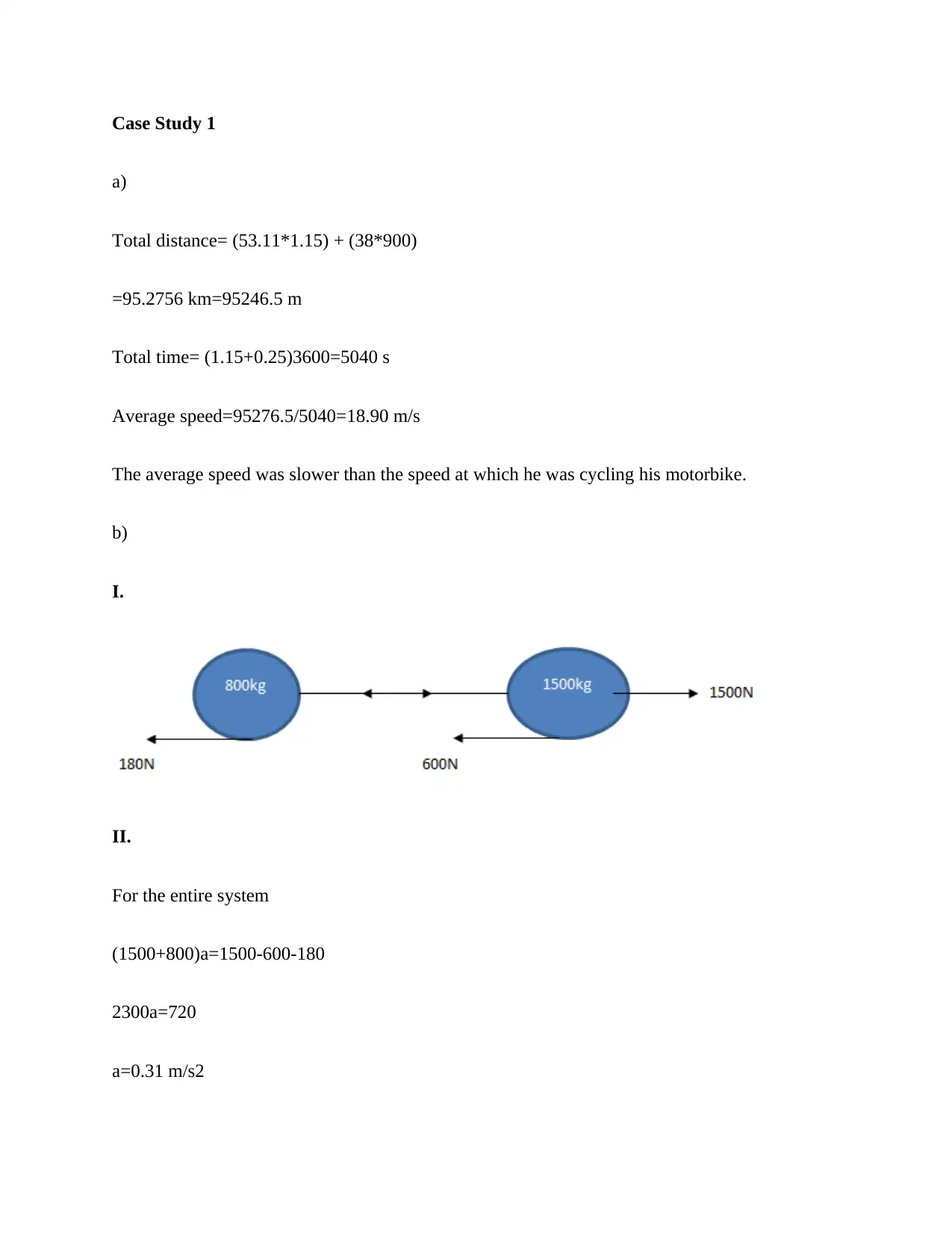
I.
II.
For the entire system
(1500+800)a=1500-600-180
2300a=720
a=0.31 m/s2
a)
Total distance= (53.11*1.15) + (38*900)
=95.2756 km=95246.5 m
Total time= (1.15+0.25)3600=5040 s
Average speed=95276.5/5040=18.90 m/s
The average speed was slower than the speed at which he was cycling his motorbike.
b)
I.
II.
For the entire system
(1500+800)a=1500-600-180
2300a=720
a=0.31 m/s2
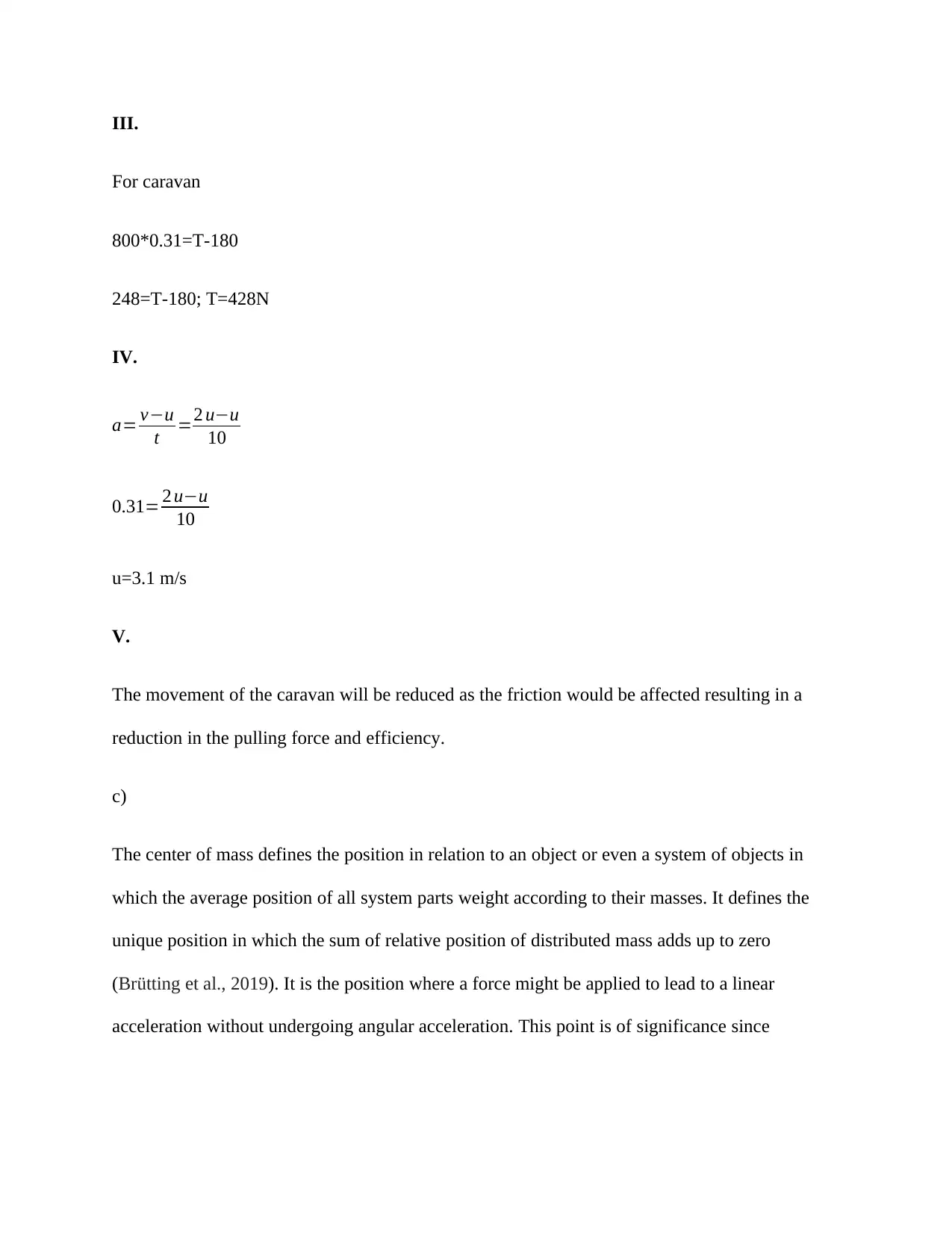
III.
For caravan
800*0.31=T-180
248=T-180; T=428N
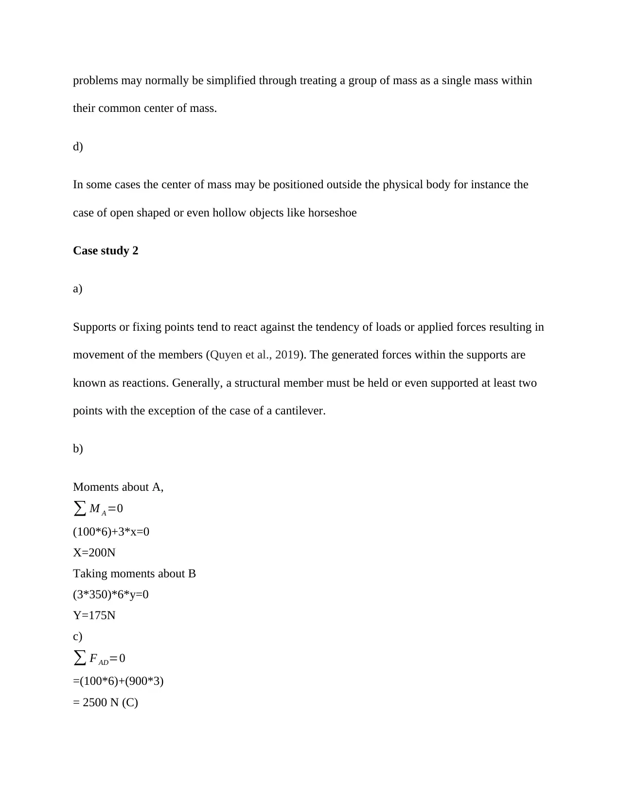
IV.
a= v−u
t =2 u−u
10
0.31= 2 u−u
10
u=3.1 m/s
V.
The movement of the caravan will be reduced as the friction would be affected resulting in a
reduction in the pulling force and efficiency.
c)
The center of mass defines the position in relation to an object or even a system of objects in
which the average position of all system parts weight according to their masses. It defines the
unique position in which the sum of relative position of distributed mass adds up to zero
(Brütting et al., 2019). It is the position where a force might be applied to lead to a linear
acceleration without undergoing angular acceleration. This point is of significance since
For caravan
800*0.31=T-180
248=T-180; T=428N
IV.
a= v−u
t =2 u−u
10
0.31= 2 u−u
10
u=3.1 m/s
V.
The movement of the caravan will be reduced as the friction would be affected resulting in a
reduction in the pulling force and efficiency.
c)
The center of mass defines the position in relation to an object or even a system of objects in
which the average position of all system parts weight according to their masses. It defines the
unique position in which the sum of relative position of distributed mass adds up to zero
(Brütting et al., 2019). It is the position where a force might be applied to lead to a linear
acceleration without undergoing angular acceleration. This point is of significance since
⊘ This is a preview!⊘
Do you want full access?
Subscribe today to unlock all pages.
Trusted by 1+ million students worldwide
problems may normally be simplified through treating a group of mass as a single mass within
their common center of mass.
d)
In some cases the center of mass may be positioned outside the physical body for instance the
case of open shaped or even hollow objects like horseshoe
Case study 2
a)
Supports or fixing points tend to react against the tendency of loads or applied forces resulting in
movement of the members (Quyen et al., 2019). The generated forces within the supports are
known as reactions. Generally, a structural member must be held or even supported at least two
points with the exception of the case of a cantilever.
b)
Moments about A,
∑ M A =0
(100*6)+3*x=0
X=200N
Taking moments about B
(3*350)*6*y=0
Y=175N
c)
∑ F AD=0
=(100*6)+(900*3)
= 2500 N (C)
Paraphrase This Document
Need a fresh take? Get an instant paraphrase of this document with our AI Paraphraser
∑ FBC=0
=(300*9)+(350*4 sin30)
3400N (T)
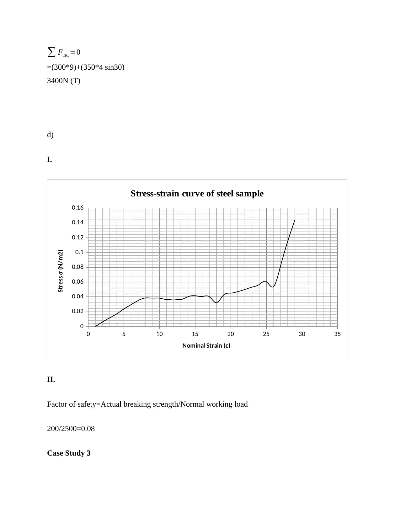
d)
I.
0 5 10 15 20 25 30 35
0
0.02
0.04
0.06
0.08
0.1
0.12
0.14
0.16
Stress-strain curve of steel sample
Nominal Strain (ε)
Stress σ (N/m2)
II.
Factor of safety=Actual breaking strength/Normal working load
200/2500=0.08
Case Study 3
=(300*9)+(350*4 sin30)
3400N (T)
d)
I.
0 5 10 15 20 25 30 35
0
0.02
0.04
0.06
0.08
0.1
0.12
0.14
0.16
Stress-strain curve of steel sample
Nominal Strain (ε)
Stress σ (N/m2)
II.
Factor of safety=Actual breaking strength/Normal working load
200/2500=0.08
Case Study 3

a)
A bimetallic strip is made up of two various materials that come with different coefficients of
expansions which are bonded together, normally copper and brass. The different expansion
compels the flat strip to bend in a direction upon heating and in the other direction upon cooling
to temperatures below the initial temperature. The metal bearing a higher thermal expansion
coefficient is placed on the exterior side of the curve upon hearing of the strip as well as on the
interior side of the curve when cooled (Boughaleb et al., 2018). The bimetallic strip effect is
applied in numerous mechanical as well as electrical gadgets including:
Clocks in which the mechanical clock mechanisms tend to be sensitive to changes in
temperatures since every part is made up of tiny tolerance resulting in errors in keeping time. A
bimetallic strip is used in the compensation of the phenomena through the construction of a
circular rim of a balance wheel which works by moving a weight in a circular manner looking at
circular plane downwards by the balance wheel changing then, the inertia momentum of the
balance wheel
Thermostats
The bimetallic strip end is fixed mechanically and linked to a source of electrical power even as
the other end is left moving which transmits electrical contact.
Thermometers
Used in direct indicating dial thermometer into the coil which aids in changing the metal
expansion linear movement to circular movement. With one end of the coil being in fixed
position to the device casing the other end moves an indicating needle within a circular indicator.
⊘ This is a preview!⊘
Do you want full access?
Subscribe today to unlock all pages.
Trusted by 1+ million students worldwide
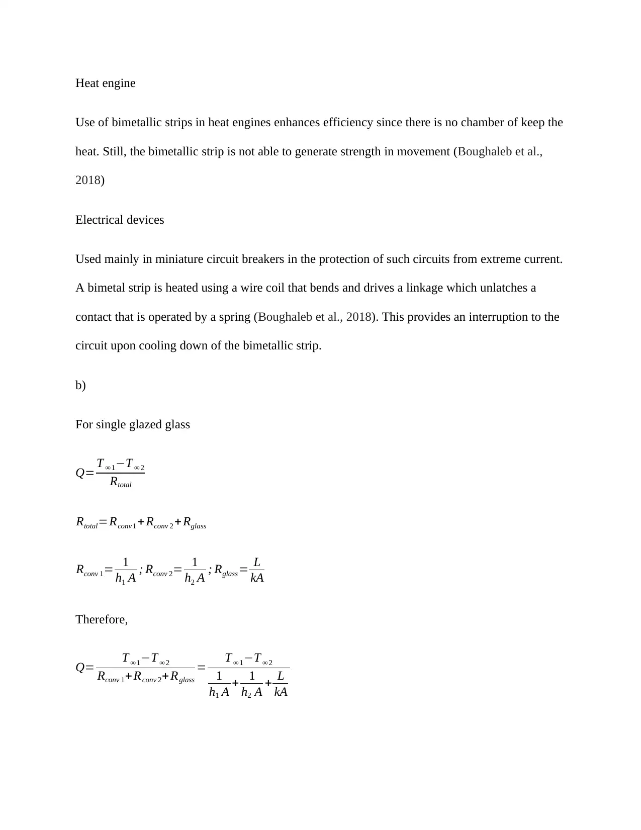
Heat engine
Use of bimetallic strips in heat engines enhances efficiency since there is no chamber of keep the
heat. Still, the bimetallic strip is not able to generate strength in movement (Boughaleb et al.,
2018)
Electrical devices
Used mainly in miniature circuit breakers in the protection of such circuits from extreme current.
A bimetal strip is heated using a wire coil that bends and drives a linkage which unlatches a
contact that is operated by a spring (Boughaleb et al., 2018). This provides an interruption to the
circuit upon cooling down of the bimetallic strip.
b)
For single glazed glass
Q= T ∞ 1−T ∞ 2
Rtotal
Rtotal=Rconv 1 + Rconv 2 + Rglass
Rconv 1= 1
h1 A ; Rconv 2= 1
h2 A ; Rglass = L
kA
Therefore,
Q= T ∞ 1−T ∞ 2
Rconv 1+Rconv 2+ Rglass
= T ∞ 1−T ∞ 2
1
h1 A + 1
h2 A + L
kA
Paraphrase This Document
Need a fresh take? Get an instant paraphrase of this document with our AI Paraphraser
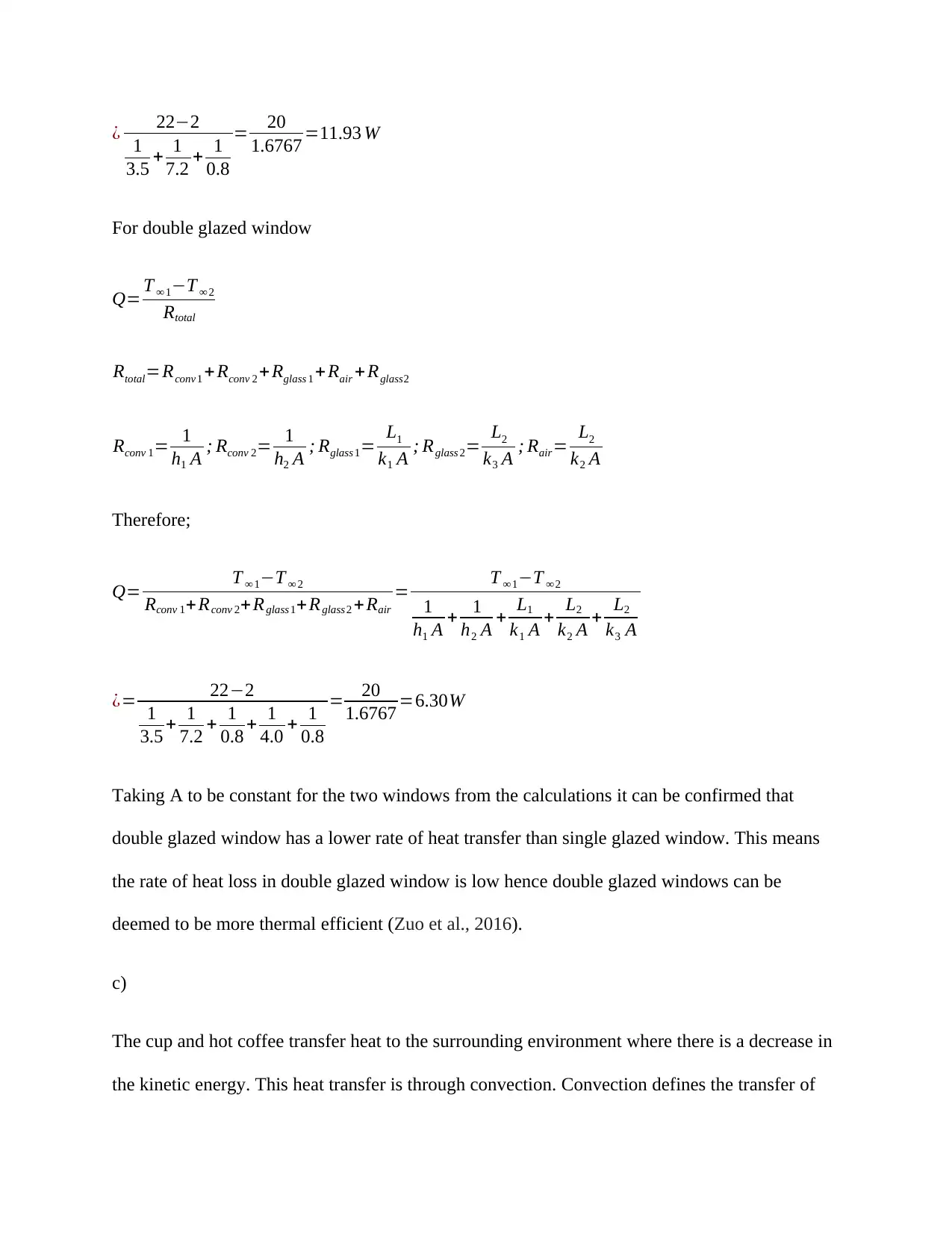
¿ 22−2
1
3.5 + 1
7.2 + 1
0.8
= 20
1.6767 =11.93 W
For double glazed window
Q= T ∞ 1−T ∞ 2
Rtotal
Rtotal=Rconv 1 + Rconv 2 + Rglass 1 + Rair + Rglass2
Rconv 1= 1
h1 A ; Rconv 2= 1
h2 A ; Rglass 1= L1
k1 A ; Rglass 2= L2
k3 A ; Rair= L2
k2 A
Therefore;
Q= T ∞ 1−T ∞ 2
Rconv 1+ Rconv 2+ Rglass 1+ Rglass 2 + Rair
= T ∞ 1−T ∞ 2
1
h1 A + 1
h2 A + L1
k1 A + L2
k2 A + L2
k3 A
¿= 22−2
1
3.5 + 1
7.2 + 1
0.8 + 1
4.0 + 1
0.8
= 20
1.6767 =6.30W
Taking A to be constant for the two windows from the calculations it can be confirmed that
double glazed window has a lower rate of heat transfer than single glazed window. This means
the rate of heat loss in double glazed window is low hence double glazed windows can be
deemed to be more thermal efficient (Zuo et al., 2016).
c)
The cup and hot coffee transfer heat to the surrounding environment where there is a decrease in
the kinetic energy. This heat transfer is through convection. Convection defines the transfer of
1
3.5 + 1
7.2 + 1
0.8
= 20
1.6767 =11.93 W
For double glazed window
Q= T ∞ 1−T ∞ 2
Rtotal
Rtotal=Rconv 1 + Rconv 2 + Rglass 1 + Rair + Rglass2
Rconv 1= 1
h1 A ; Rconv 2= 1
h2 A ; Rglass 1= L1
k1 A ; Rglass 2= L2
k3 A ; Rair= L2
k2 A
Therefore;
Q= T ∞ 1−T ∞ 2
Rconv 1+ Rconv 2+ Rglass 1+ Rglass 2 + Rair
= T ∞ 1−T ∞ 2
1
h1 A + 1
h2 A + L1
k1 A + L2
k2 A + L2
k3 A
¿= 22−2
1
3.5 + 1
7.2 + 1
0.8 + 1
4.0 + 1
0.8
= 20
1.6767 =6.30W
Taking A to be constant for the two windows from the calculations it can be confirmed that
double glazed window has a lower rate of heat transfer than single glazed window. This means
the rate of heat loss in double glazed window is low hence double glazed windows can be
deemed to be more thermal efficient (Zuo et al., 2016).
c)
The cup and hot coffee transfer heat to the surrounding environment where there is a decrease in
the kinetic energy. This heat transfer is through convection. Convection defines the transfer of
heat through movement of the warmed particles. Heat gets out of the coffee cup in the form of
steam currents as well as air rise. Convection defines heat energy transfer within a gas or liquid
through the movement t of currents. The heat tends to move with the liquid.
The method of heat transfer when heating up a room using electric fan is called forced
convection (Li, Allinson and Lomax, 2019). This is a unique kind of heat transfer where the
fluids are engaged in forceful movement to enhance the transfer of heat. In this method of heat
transfer air undergoes heating within the fan and then pushed via the house using a blower. The
blower releases a certain amount of air and the output air is divided among the available output
grills.
The difference between natural convection and forced convection can be noticed in temperature
difference. Natural convection occurs in case where a section of the house is warmer even as the
other is cold. Forced convection on the other hand generates a temperature that is more uniform
and thus comfortable all over the room resulting in a reduction of cold spots within the house
(Johnston et al., 2016).
⊘ This is a preview!⊘
Do you want full access?
Subscribe today to unlock all pages.
Trusted by 1+ million students worldwide
References
Boughaleb, J., Arnaud, A., Guiffard, B., Guyomar, D., Seveno, R., Monfray, S., Skotnicki, T.
and Cottinet, P.J., 2018. Coupling of PZT thin films with bimetallic strip heat engines for
thermal energy harvesting. Sensors, 18(6), p.1859
Brütting, J., Desruelle, J., Senatore, G. and Fivet, C., 2019, April. Design of Truss Structures
Through Reuse. In Structures (Vol. 18, pp. 128-137). Elsevier
Johnston, D., Farmer, D., Brooke-Peat, M. and Miles-Shenton, D., 2016. Bridging the domestic
building fabric performance gap. Building Research & Information, 44(2), pp.147-159
Li, M., Allinson, D. and Lomax, K., 2019. Estimation of building heat transfer coefficients from
in-use data. International Journal of Building Pathology and Adaptation
Quyen, V.T.B., Khanh, C.Q., Van, T.T.T., Khoa, D.N. and Truc, T.P., 2019, November. A New
Algorithm for Size Optimization of the Truss Structures with Buckling Constraint using Finite
Element Method. In IOP Conference Series: Materials Science and Engineering (Vol. 661, No.
1, p. 012041). IOP Publishing
Paraphrase This Document
Need a fresh take? Get an instant paraphrase of this document with our AI Paraphraser
Zuo, W., Wetter, M., Tian, W., Li, D., Jin, M. and Chen, Q., 2016. Coupling indoor airflow,
HVAC, control and building envelope heat transfer in the Modelica Buildings library. Journal of
Building Performance Simulation, 9(4), pp.366-381
HVAC, control and building envelope heat transfer in the Modelica Buildings library. Journal of
Building Performance Simulation, 9(4), pp.366-381
1 out of 11
Your All-in-One AI-Powered Toolkit for Academic Success.
+13062052269
info@desklib.com
Available 24*7 on WhatsApp / Email
![[object Object]](/_next/static/media/star-bottom.7253800d.svg)
Unlock your academic potential
Copyright © 2020–2026 A2Z Services. All Rights Reserved. Developed and managed by ZUCOL.