Analysis and Design of a Twin-Tube Heat Exchanger Project
VerifiedAdded on 2020/05/28
|8
|1521
|176
Project
AI Summary
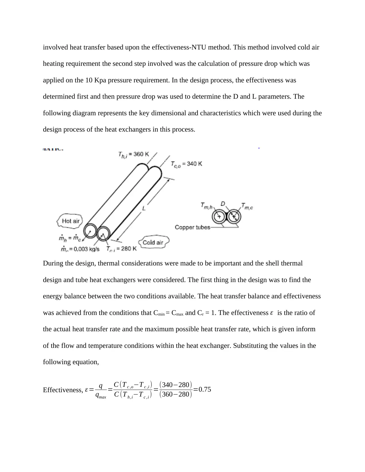
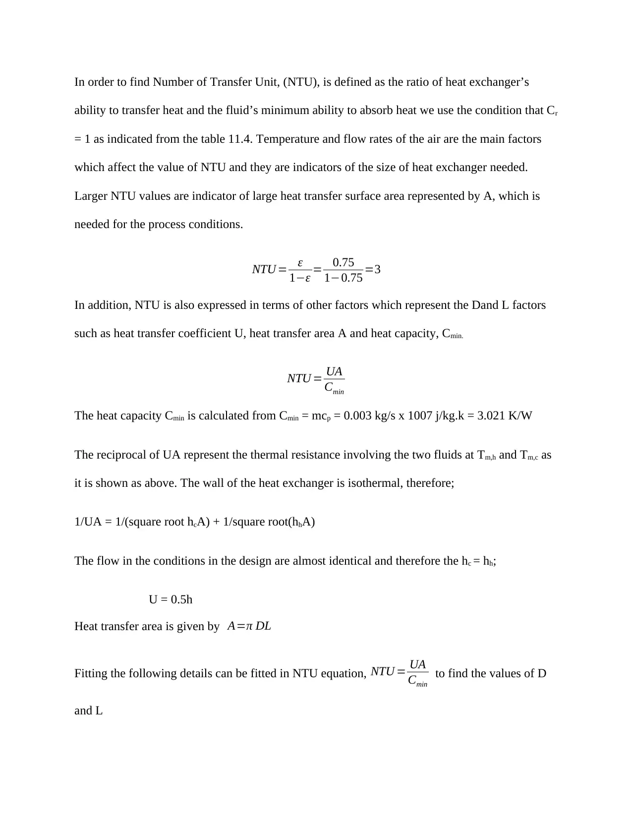
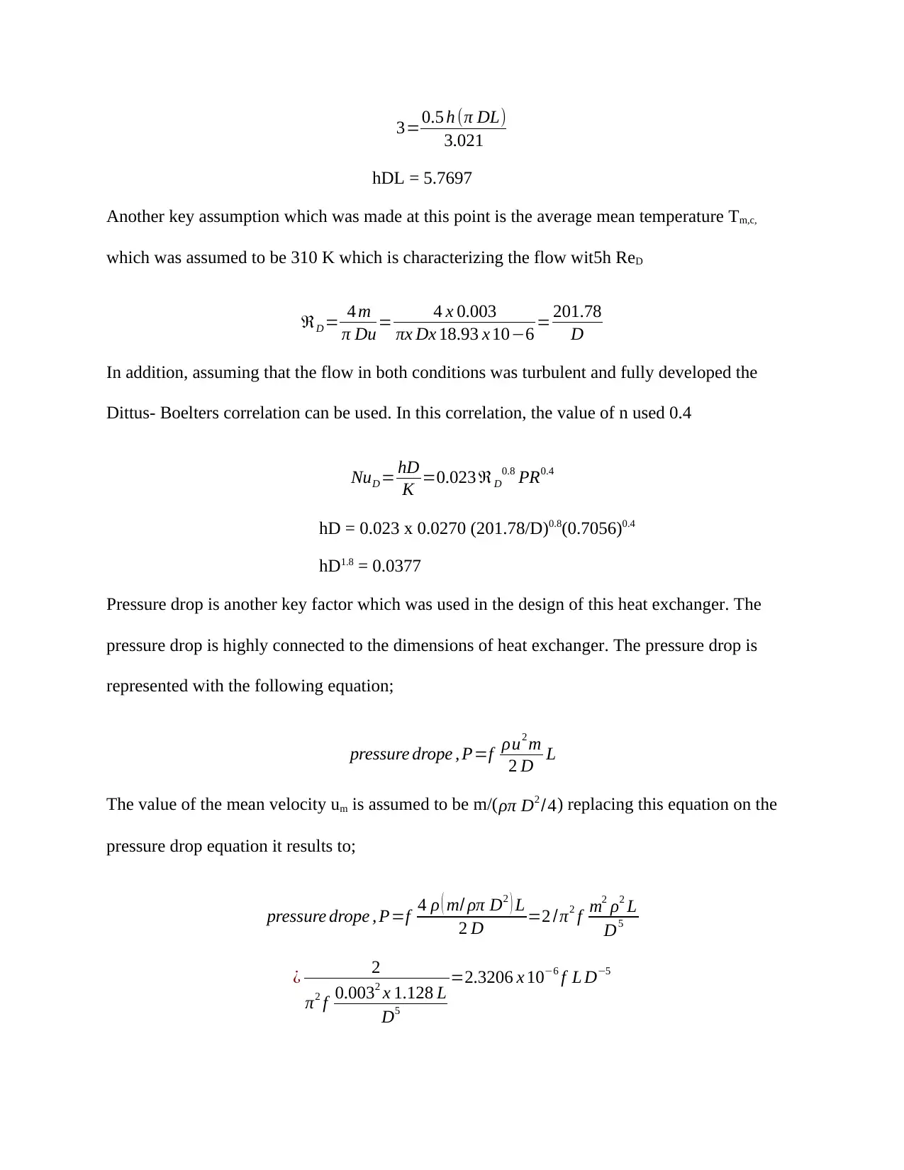
This project focuses on the design of a twin-tube counter-flow heat exchanger, a device used to transfer thermal energy between two fluids at different temperatures. The design process involves balancing flow rates, considering the walls as fins, and making assumptions about pressure and temperature. The project aims to determine the optimal diameter and length of the heat exchanger using the effectiveness-NTU method, calculating pressure drop, and analyzing the Reynolds number. The analysis includes thermal considerations, energy balances, and the use of the Dittus-Boelter correlation. The final results provide dimensions for the heat exchanger and analysis of outlet temperatures, heat transfer rates, and pressure drops. The project concludes with a discussion of the design parameters and relevant plots.

Name:
Course:
Professor:
Date:
Course:
Professor:
Date:
Paraphrase This Document
Need a fresh take? Get an instant paraphrase of this document with our AI Paraphraser

Heat exchange analysis
Heat exchanger is a piece of equipment which helps in transferring thermal energy between two
or more fluids which happens to be at different temperatures. The heat exchangers are used in
heating and also in air conditioning applications. Also the devices are also applied in industries
such as chemical and food industries as well as electrical power generation. In addition, heat
exchangers are also applied in everyday activities on activities such as hot water radiations and
also car cooling systems. High temperature exchangers are frequently employed for preheating
combustion air for industrial burners. The design of heat exchangers is critical to enhance their
effectiveness of heat and pressure transfer. In the design, the diameter and length of the heat
exchanger devices are important to enhance the effectiveness of the devices. This project was
able to focus on the design of twin-tube counter flow heat exchanger. The major conditions on
this device are that it works to balance flow rates between the cold and hot air streams. In
addition, during the design, the walls of the device were believed to act as fins and have an
efficiency of 100%. Another key assumption which was made is that the average pressure of the
air stream was taken to be 1 atm. In addition, the maximum allowable pressure drop for the cold
air was 10 Kpa. The temperature for the cold air was taken to be 280 K and it was to be increased
to 340 K through the use of hot air stream of 360 K. Other key assumptions which were used
during the design include steady-state conditions. In addition heat losses to the surrounding were
assumed to be negligible and the flow was fully developed. The design process was meant to
determine the appropriate diameter D and length T for the twin-tube counter flow heat
exchanger.
In the aim to achieve at the best dimension of heat exchanger, two key specification methods for
the diameter D and length L were recommended which was done through the method which

involved heat transfer based upon the effectiveness-NTU method. This method involved cold air
heating requirement the second step involved was the calculation of pressure drop which was
applied on the 10 Kpa pressure requirement. In the design process, the effectiveness was
determined first and then pressure drop was used to determine the D and L parameters. The
following diagram represents the key dimensional and characteristics which were used during the
design process of the heat exchangers in this process.
During the design, thermal considerations were made to be important and the shell thermal
design and tube heat exchangers were considered. The first thing in the design was to find the
energy balance between the two conditions available. The heat transfer balance and effectiveness
was achieved from the conditions that Cmin = Cmax and Cr = 1. The effectiveness ε is the ratio of
the actual heat transfer rate and the maximum possible heat transfer rate, which is given inform
of the flow and temperature conditions within the heat exchanger. Substituting the values in the
following equation,
Effectiveness, ε = q
qmax
=C (T c ,o−T c ,i )
C (T h ,i−T c ,i ) =(340−280)
(360−280) =0.75
⊘ This is a preview!⊘
Do you want full access?
Subscribe today to unlock all pages.

Trusted by 1+ million students worldwide

In order to find Number of Transfer Unit, (NTU), is defined as the ratio of heat exchanger’s
ability to transfer heat and the fluid’s minimum ability to absorb heat we use the condition that Cr
= 1 as indicated from the table 11.4. Temperature and flow rates of the air are the main factors
which affect the value of NTU and they are indicators of the size of heat exchanger needed.
Larger NTU values are indicator of large heat transfer surface area represented by A, which is
needed for the process conditions.
NTU = ε
1−ε = 0.75
1−0.75 =3
In addition, NTU is also expressed in terms of other factors which represent the Dand L factors
such as heat transfer coefficient U, heat transfer area A and heat capacity, Cmin.
NTU = UA
Cmin
The heat capacity Cmin is calculated from Cmin = mcp = 0.003 kg/s x 1007 j/kg.k = 3.021 K/W
The reciprocal of UA represent the thermal resistance involving the two fluids at Tm,h and Tm,c as
it is shown as above. The wall of the heat exchanger is isothermal, therefore;
1/UA = 1/(square root hcA) + 1/square root(hhA)
The flow in the conditions in the design are almost identical and therefore the hc = hh;
U = 0.5h
Heat transfer area is given by A=π DL
Fitting the following details can be fitted in NTU equation, NTU = UA
Cmin
to find the values of D
and L
Paraphrase This Document
Need a fresh take? Get an instant paraphrase of this document with our AI Paraphraser

3=0.5 h (π DL)
3.021
hDL = 5.7697
Another key assumption which was made at this point is the average mean temperature Tm,c,
which was assumed to be 310 K which is characterizing the flow wit5h ReD
ℜD = 4 m
π Du= 4 x 0.003
πx Dx 18.93 x 10−6 = 201.78
D
In addition, assuming that the flow in both conditions was turbulent and fully developed the
Dittus- Boelters correlation can be used. In this correlation, the value of n used 0.4
NuD = hD
K =0.023 ℜD
0.8 PR0.4
hD = 0.023 x 0.0270 (201.78/D)0.8(0.7056)0.4
hD1.8 = 0.0377
Pressure drop is another key factor which was used in the design of this heat exchanger. The
pressure drop is highly connected to the dimensions of heat exchanger. The pressure drop is
represented with the following equation;
pressure drope , P=f ρu2 m
2 D L
The value of the mean velocity um is assumed to be m/( ρπ D2 /4) replacing this equation on the
pressure drop equation it results to;
pressure drope , P=f 4 ρ ( m/ ρπ D2 ) L
2 D =2 /π2 f m2 ρ2 L
D5
¿ 2
π2 f 0.0032 x 1.128 L
D5
=2.3206 x 10⁻⁶ f L D−5

From the initial details, the pressure drop requirement is supposed to be 10 Kpa which is equal to
10,000 N/m2. Therefore, the following can be achieved;
f L D−5=4.3092 x 10¹⁰
The analysis of the result using Reynolds number range will be important in arriving at the
coming up with the dimensions of the diameter D and length L of heat exchanger. The range of
Reynolds number is taken to be in the range of 3,000 ≤ 5 x 10⁶. This can be filled in the
following equation as follows in order to enhance the analysis and design of the heat exchanger
and come up with the different details.
f ={(0.790 δn ( ℜD )−1.46)}−2
f ={(0.790 δn201.78 /D−1.46)}−2
From design so far, there are 4 key unknown values which include D, L, f and h. the IHT
workspace is important in determining the values to enhance the coming up with the different
values. From the analysis in the IHT work space, the value of the different design parameter is
found to be
D = 8.96 mm,
L = 3.52 mm,
f = 0.02538 and
h = 182.9 W/m2. K
In the analysis to find the configuration shows that ReD = 22,520 due to the flow was assumed to
be turbulent and L/D = 3.52/0.00896 = 390 ˃˃ 10 which is fully a developed assumption, and it
is reasonable.
⊘ This is a preview!⊘
Do you want full access?
Subscribe today to unlock all pages.

Trusted by 1+ million students worldwide

In addition, the next step in the analysis was to analyze the plots of cold stream outlet
temperatures, heat transfer rate and pressure drops. The following flow diagrams were achieved
from the analysis part of the analysis.
From the analysis, outlet temperature of cold air Tco is seen to be tactless to flow rate. The outlet
temperature is able to follow heat rate, q, which is almost relative to flow rate as in the q vs m
plots. The pressure drop I also able to vary with the changes in mean velocity squared.
In conclusion, the details of the design were able to arrive at the perfect dimensions which were
able to enhance the design of the heat exchanger.
Paraphrase This Document
Need a fresh take? Get an instant paraphrase of this document with our AI Paraphraser

References
Coulson,J.M. and Richardson,J.F. (2003) Chemical Engineering Vol 1, 4th edition (Pergamon)
Hewitt,G.F. et al (2014). Process Heat Transfer, (CRC Press)
Incropera F. P. & DeWitt D. P. (2009). Fundamentals of Heat and Mass Transfer, 3rd edition,
pp. 658–660. Wiley, New York
Incropera, F. P DeWitt,. D. P. Bergman T. L. & Lavine A. S. (2006). Fundamentals of Heat and
Mass Transfer ,6th edition, pp 686–688. John Wiley & Sons US
Jeff, S. (2013). Fundamentals of Momentum, Heat and Mass Transfer. S.l.: John Wiley & Sons,
2013. Print.
Kern,D.Q. (2010) Process Heat Transfer (McGraw Hill)
Perry,R.H. and Green, D. (2014) Perry’s Chemical Engineers Handbook, 6th edition (McGraw
Hill)
Skinnet,R.K. (2009) Coulson & Richardson’s Chemical Engineering Vol 6, 2nd edition (Pergamo
1 out of 8
Related Documents

Your All-in-One AI-Powered Toolkit for Academic Success.
+13062052269
info@desklib.com
Available 24*7 on WhatsApp / Email
Unlock your academic potential
Copyright © 2020–2025 A2Z Services. All Rights Reserved. Developed and managed by ZUCOL.