Melbourne Uni, MCEN90012: Static Equilibrium Design Analysis

Verified

Added on  2023/01/17

|9
|991
|29
Practical Assignment
AI Summary
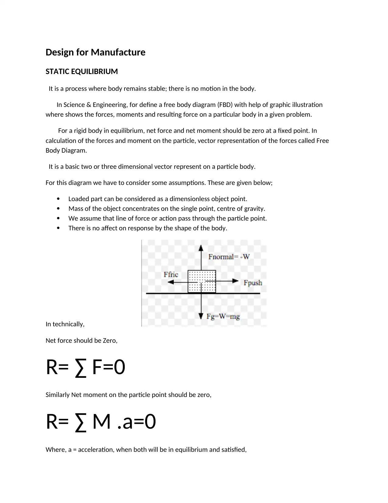
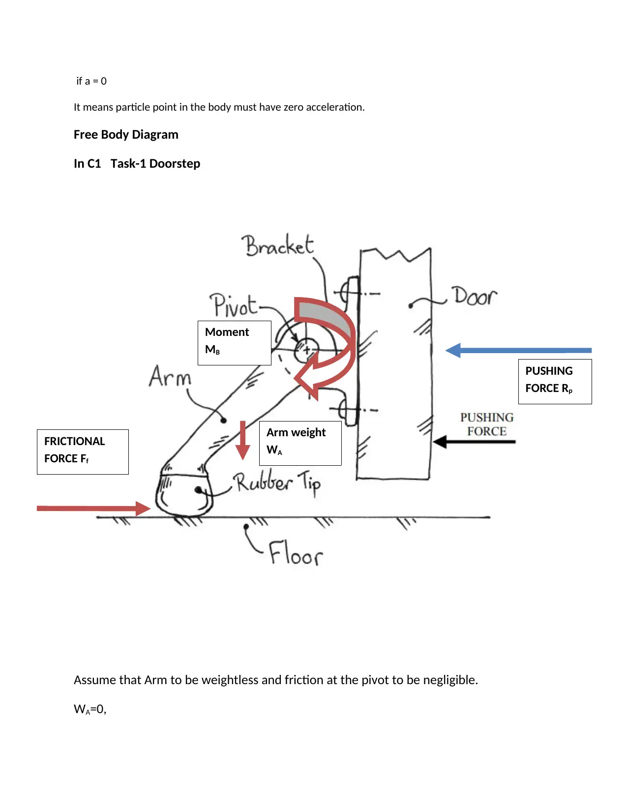
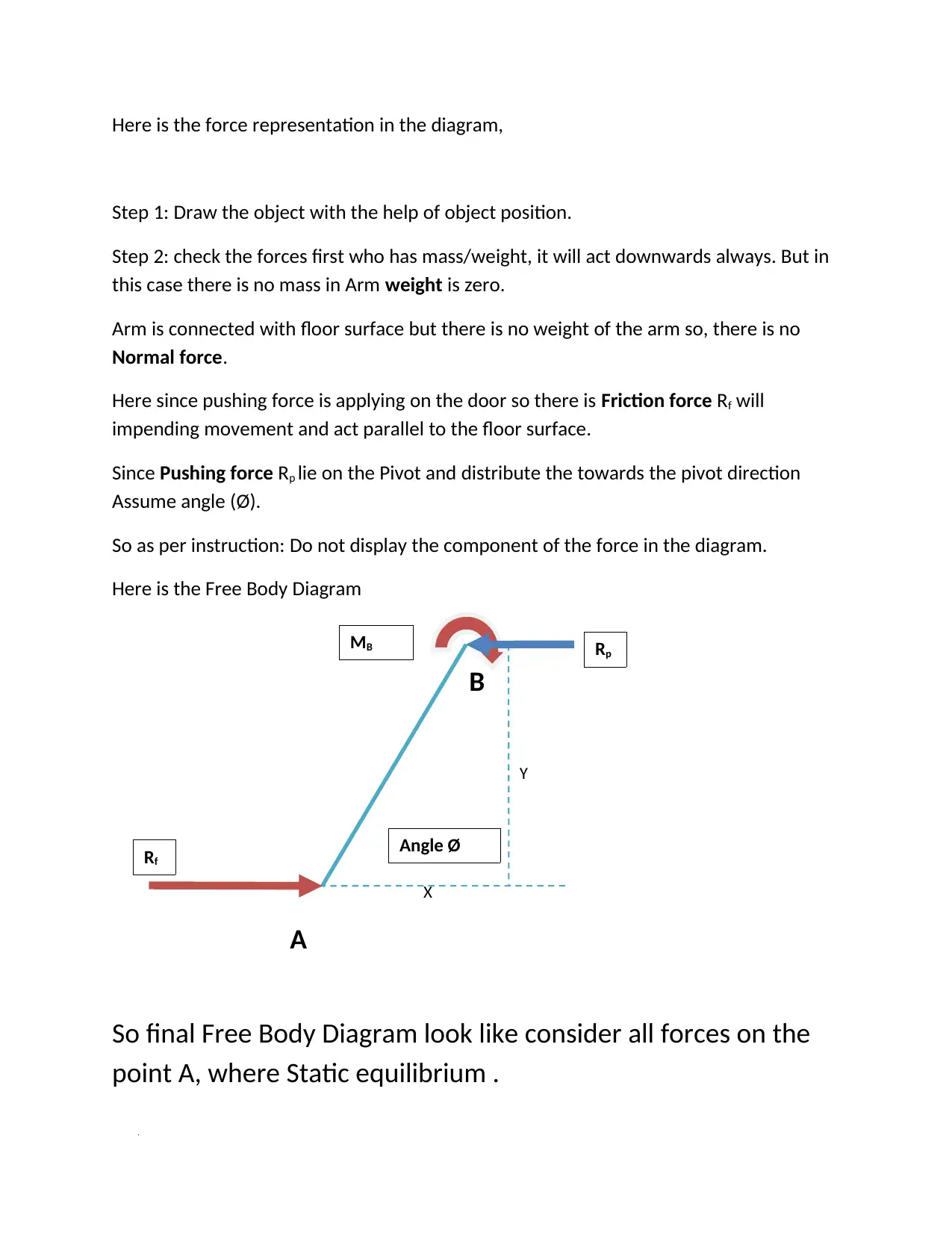
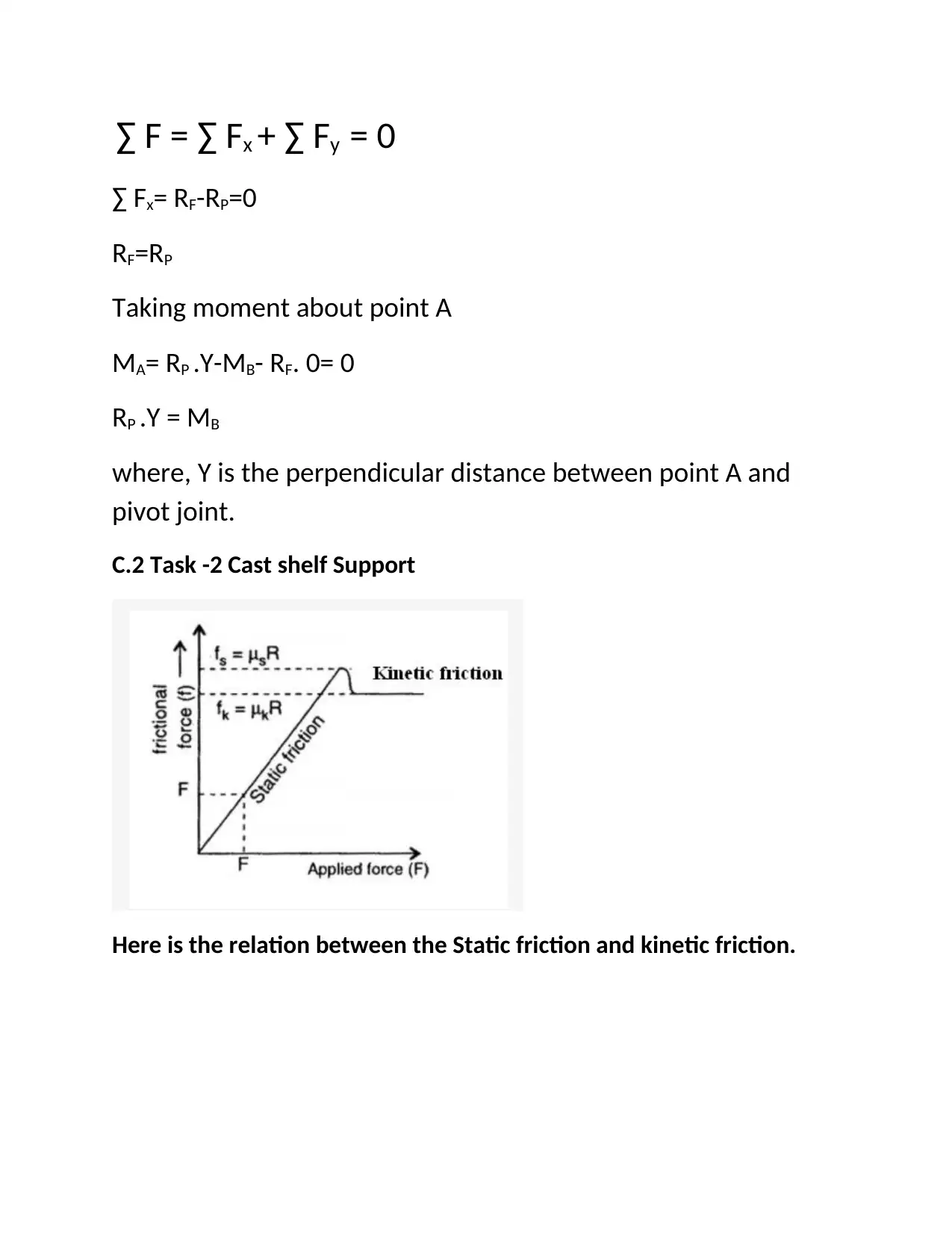
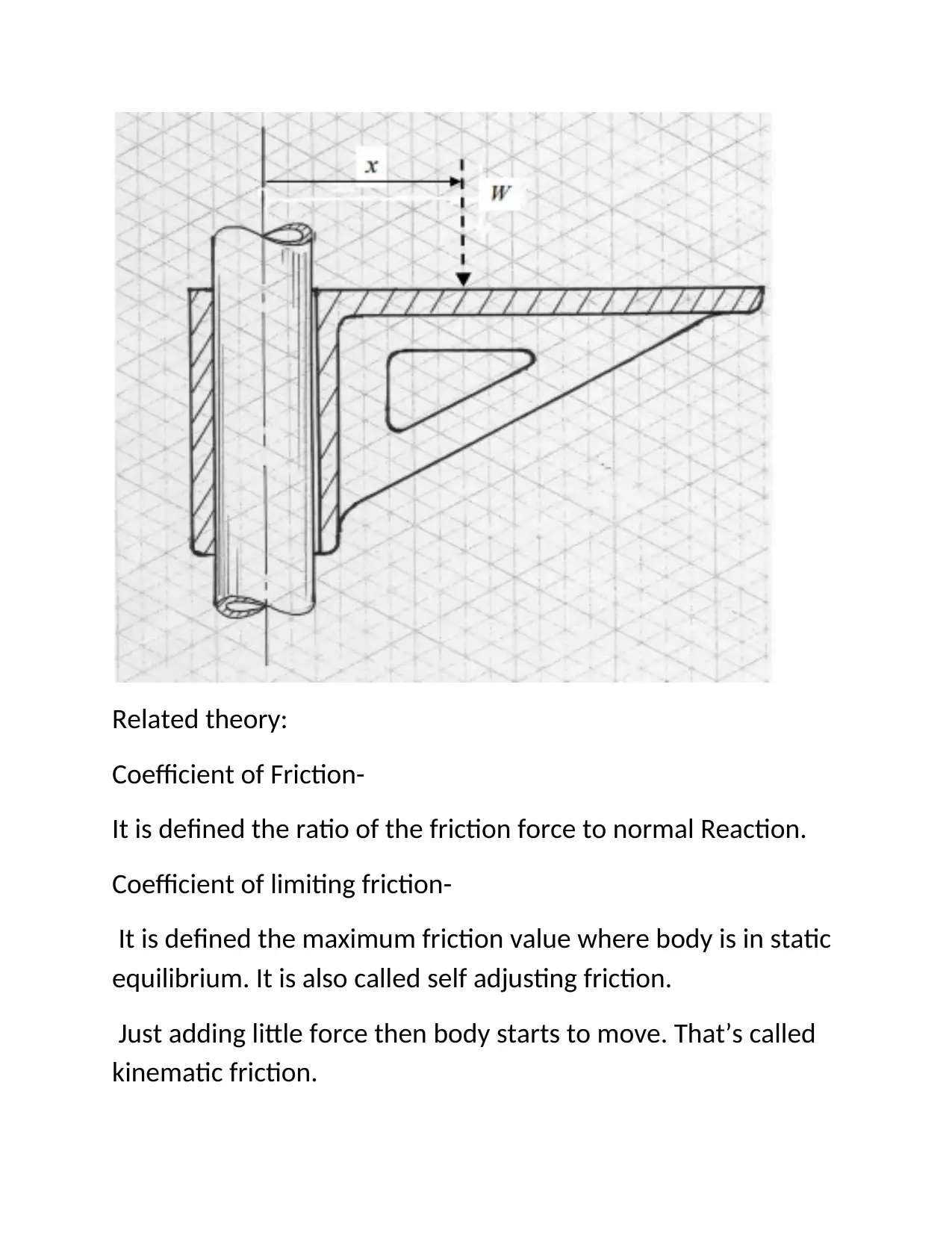
This document presents a student's analysis of static equilibrium, focusing on its application in mechanical engineering design. The assignment begins with a theoretical overview of static equilibrium, defining it as a state where a body remains stable without motion, and explaining the concept of free body diagrams (FBDs) as a graphical representation of forces and moments. The solution includes examples, such as a trap door counterbalance system, detailing the design of a torsion bar and calculating relevant parameters like length, diameter, and torque. The analysis extends to different scenarios, like a cast shelf support, discussing static and kinetic friction. The document provides detailed calculations, diagrams, and explanations. It includes an assignment brief outlining the problem and the requirements of the task, including the design of a spring for a trap door, considering weight, torque, and angular displacement. It also analyzes the forces and moments acting on the door, demonstrating the practical application of static equilibrium principles in mechanical design.
Document Page
Design for Manufacture
STATIC EQUILIBRIUM
It is a process where body remains stable; there is no motion in the body.
In Science & Engineering, for define a free body diagram (FBD) with help of graphic illustration
where shows the forces, moments and resulting force on a particular body in a given problem.
For a rigid body in equilibrium, net force and net moment should be zero at a fixed point. In
calculation of the forces and moment on the particle, vector representation of the forces called Free
Body Diagram.
It is a basic two or three dimensional vector represent on a particle body.
For this diagram we have to consider some assumptions. These are given below;
Loaded part can be considered as a dimensionless object point.
Mass of the object concentrates on the single point, centre of gravity.
We assume that line of force or action pass through the particle point.
There is no affect on response by the shape of the body.
In technically,
Net force should be Zero,
R= F=0
Similarly Net moment on the particle point should be zero,
R= M .a=0
Where, a = acceleration, when both will be in equilibrium and satisfied,
tabler-icon-diamond-filled.svg

Secure Best Marks with AI Grader

Need help grading? Try our AI Grader for instant feedback on your assignments.
Document Page
if a = 0
It means particle point in the body must have zero acceleration.
Free Body Diagram
In C1 Task-1 Doorstep
Assume that Arm to be weightless and friction at the pivot to be negligible.
WA=0,
PUSHING
FORCE Rp
FRICTIONAL
FORCE Ff
Moment
MB
Arm weight
WA
Document Page
Here is the force representation in the diagram,
Step 1: Draw the object with the help of object position.
Step 2: check the forces first who has mass/weight, it will act downwards always. But in
this case there is no mass in Arm weight is zero.
Arm is connected with floor surface but there is no weight of the arm so, there is no
Normal force.
Here since pushing force is applying on the door so there is Friction force Rf will
impending movement and act parallel to the floor surface.
Since Pushing force Rp lie on the Pivot and distribute the towards the pivot direction
Assume angle (Ø).
So as per instruction: Do not display the component of the force in the diagram.
Here is the Free Body Diagram
B
Y
X
A
So final Free Body Diagram look like consider all forces on the
point A, where Static equilibrium .
Rp
MB
Rf
Angle Ø
Document Page
∑ F = ∑ Fx + ∑ Fy = 0
∑ Fx= RF-RP=0
RF=RP
Taking moment about point A
MA= RP .Y-MB- RF. 0= 0
RP .Y = MB
where, Y is the perpendicular distance between point A and
pivot joint.
C.2 Task -2 Cast shelf Support
Here is the relation between the Static friction and kinetic friction.
tabler-icon-diamond-filled.svg

Secure Best Marks with AI Grader

Need help grading? Try our AI Grader for instant feedback on your assignments.
Document Page
Related theory:
Coefficient of Friction-
It is defined the ratio of the friction force to normal Reaction.
Coefficient of limiting friction-
It is defined the maximum friction value where body is in static
equilibrium. It is also called self adjusting friction.
Just adding little force then body starts to move. That’s called
kinematic friction.
Document Page
Kinematic friction always less than max. Limiting friction
fSMAX α R
fSMAX = μ R
μ= fSMAX/R
Where, μ is Coefficient of friction
In this case limiting friction μ is 0.577
so tan30˚=0.577
When the value of X=0
There is sliding the body, after gradually increase the value
of X, value of friction will increase according to Coefficient of
friction, but that limit when applied force will be equal to the
friction force so body will not slide. That part is call liming
friction.
Applied force on the tube = w, consider that from distance r
both will be in equilibrium condition,
M= W.X - FR.r = 0
X= FR.r/W
Where FR is frictional force,
FR= μ.R
X= μ (R.r/W)
Document Page
Here we have value for μ=0.577 so apply on it, then according to the value of W and R.
Kinematic friction will be lesser than the static friction as shown in the graph.
Some detail about theory of friction given below:
Case-I
Here is best example, we have friction between the surface and body part, friction
force is applicable. So body will move upward direction with P-F+ component of force.
tabler-icon-diamond-filled.svg

Paraphrase This Document

Need a fresh take? Get an instant paraphrase of this document with our AI Paraphraser
Document Page
Case-II
when body have not friction between surface and body. There is no friction so body will move
upward direction with P force.
If the particle is in equilibrium so the forces result will be acting on it is zero.
For solving this type of problem, draw the free body diagram where all forces will be
applicable at certain point with specific angle and result, that point where all condition must be
satisfied at equilibrium.
Rx= ΣFx =0 (in X- direction)
Ry= ΣFy =0 (in Y- direction)
(applicable in case of three dimension )
Rz= ΣFz =0 (in Z- direction)
Document Page
Reference:
Rosengrant, D., Van Heuvelen, A., & Etkina, E. (2009)
Do students use and understand free-body diagrams? Physics Education
Research 5(1)
Rana, N.C., and Joag, P.S. (2011) Classical Mechanics. West Patel Nagar, New Delhi. Tata
McGraw-Hill
Renn, J., Damerow, P., McLaughlin, & P. Aristotle (2010) the Origin of Mechanics: The
Perspective of Historical Epistemology. Berlin: Max Planck Institute for the
History of Science
chevron_up_icon
1 out of 9
circle_padding
hide_on_mobile
zoom_out_icon
[object Object]