Heat Transfer and Heat Exchanger Analysis: Assignment Solution
VerifiedAdded on 2022/09/09
|8
|1105
|17
Homework Assignment
AI Summary
This document presents a detailed solution to a mechanical engineering assignment on heat transfer. It begins with an analysis of heat conduction based on Fourier's law, thermal resistance, and the calculation of heat transfer rates through different materials. The solution then delves into heat exchanger analysis, including calculations of heat transfer rates, LMTD, and surface area, considering both parallel and counter-flow configurations. The assignment further explores heat transfer by radiation, calculating heat loss from a furnace and evaluating its efficiency. Finally, it compares parallel and counter-flow heat exchangers and discusses the impact of temperature profiles. All calculations and analyses are presented with clear explanations and relevant formulas, making it a comprehensive resource for students studying heat transfer.
Contents
Question 1..................................................................................................................................1
Part A.....................................................................................................................................1
Part B......................................................................................................................................2
Part C......................................................................................................................................2
Part D.....................................................................................................................................3
Question 2..................................................................................................................................4
Part A.....................................................................................................................................4
Part B......................................................................................................................................5
Question 3..................................................................................................................................5
Part A.....................................................................................................................................5
Part B......................................................................................................................................6
Part C......................................................................................................................................6
Question 4..................................................................................................................................7
Part A.....................................................................................................................................7
References..................................................................................................................................8
Paraphrase This Document
Need a fresh take? Get an instant paraphrase of this document with our AI Paraphraser
Question 1
Part A
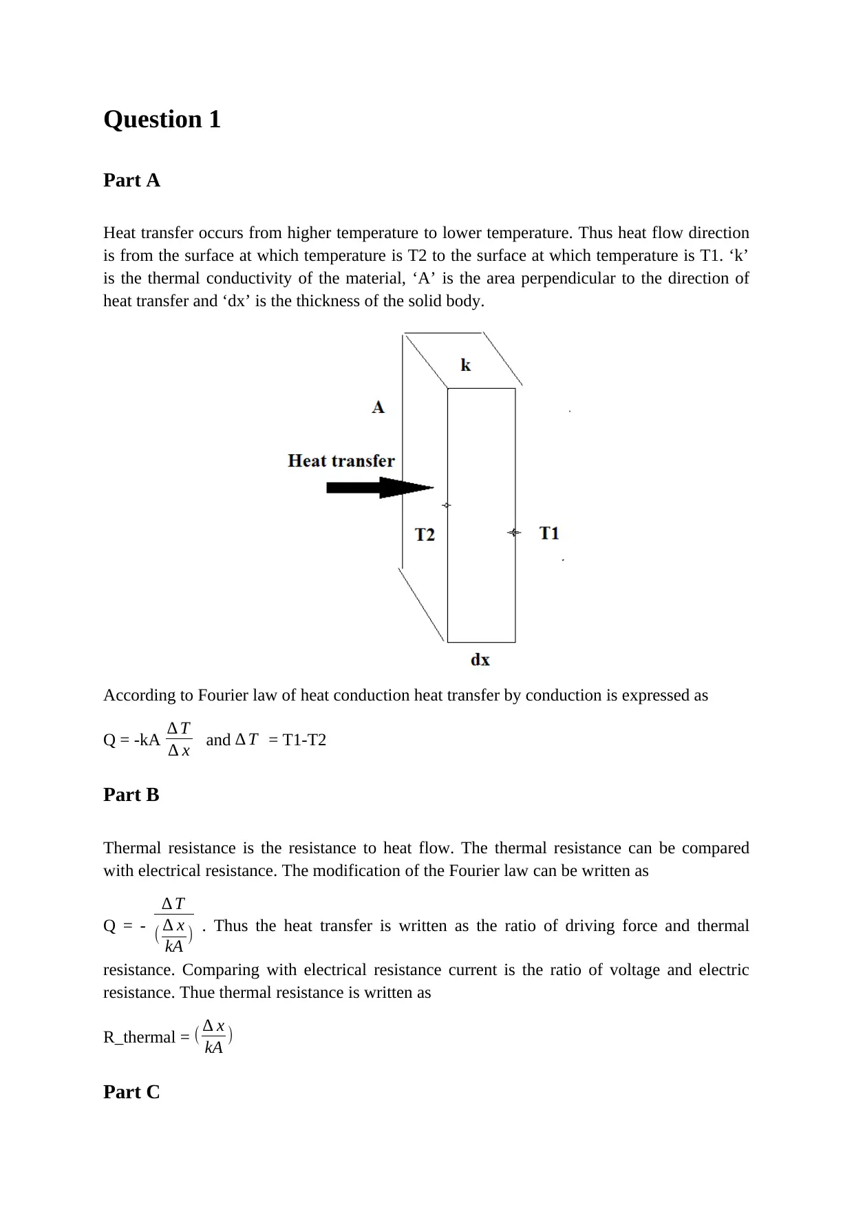
Heat transfer occurs from higher temperature to lower temperature. Thus heat flow direction
is from the surface at which temperature is T2 to the surface at which temperature is T1. ‘k’
is the thermal conductivity of the material, ‘A’ is the area perpendicular to the direction of
heat transfer and ‘dx’ is the thickness of the solid body.
According to Fourier law of heat conduction heat transfer by conduction is expressed as
Q = -kA ∆ T
∆ x and ∆ T = T1-T2
Part B
Thermal resistance is the resistance to heat flow. The thermal resistance can be compared
with electrical resistance. The modification of the Fourier law can be written as
Q = -
∆ T
( ∆ x
kA ) . Thus the heat transfer is written as the ratio of driving force and thermal
resistance. Comparing with electrical resistance current is the ratio of voltage and electric
resistance. Thue thermal resistance is written as
R_thermal = ( ∆ x
kA )
Part C

The total thermal resistance of the following system is
∑ Rthermal=∑ Rconduction+∑ Rconvection
∑ Rthermal = 1
h1 A1
+ L1
k1 A1
+ L2
k2 A2
+ 1
h2 A2
Since the area is the same
∑ Rthermal = 1
h1
+ L1
k1
+ L2
k2
+ 1
h2
Part D
The thermal resistance of the whole system is expressed as
R1 = ∆ x
kA = 0.01/2.5/0.12 = 0.033 C/W
R2 = ∆ x
kA = 0.05/18/0.04 = 0.156 C/W
R3 = ∆ x
kA = 0.05/7/0.04 = 0.1785 C/W
⊘ This is a preview!⊘
Do you want full access?
Subscribe today to unlock all pages.

Trusted by 1+ million students worldwide
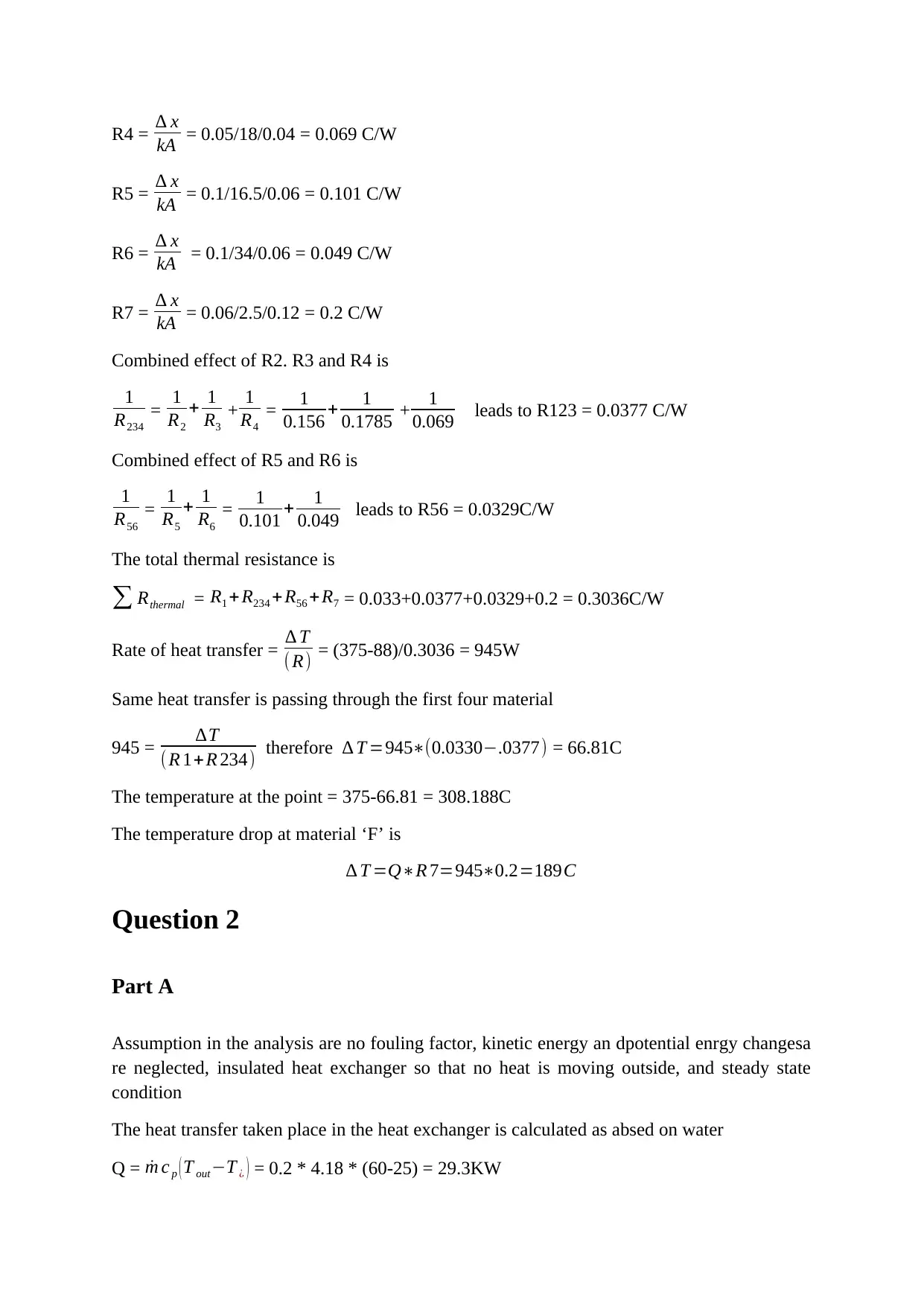
R4 = ∆ x
kA = 0.05/18/0.04 = 0.069 C/W
R5 = ∆ x
kA = 0.1/16.5/0.06 = 0.101 C/W
R6 = ∆ x
kA = 0.1/34/0.06 = 0.049 C/W
R7 = ∆ x
kA = 0.06/2.5/0.12 = 0.2 C/W
Combined effect of R2. R3 and R4 is
1
R234
= 1
R2
+ 1
R3
+ 1
R4
= 1
0.156 + 1
0.1785 + 1
0.069 leads to R123 = 0.0377 C/W
Combined effect of R5 and R6 is
1
R56
= 1
R5
+ 1
R6
= 1
0.101 + 1
0.049 leads to R56 = 0.0329C/W
The total thermal resistance is
∑ Rthermal = R1 + R234 +R56 +R7 = 0.033+0.0377+0.0329+0.2 = 0.3036C/W
Rate of heat transfer = ∆ T
( R) = (375-88)/0.3036 = 945W
Same heat transfer is passing through the first four material
945 = ∆T
( R 1+R 234) therefore ∆ T =945∗(0.0330−.0377) = 66.81C
The temperature at the point = 375-66.81 = 308.188C
The temperature drop at material ‘F’ is
∆ T =Q∗R 7=945∗0.2=189C
Question 2
Part A
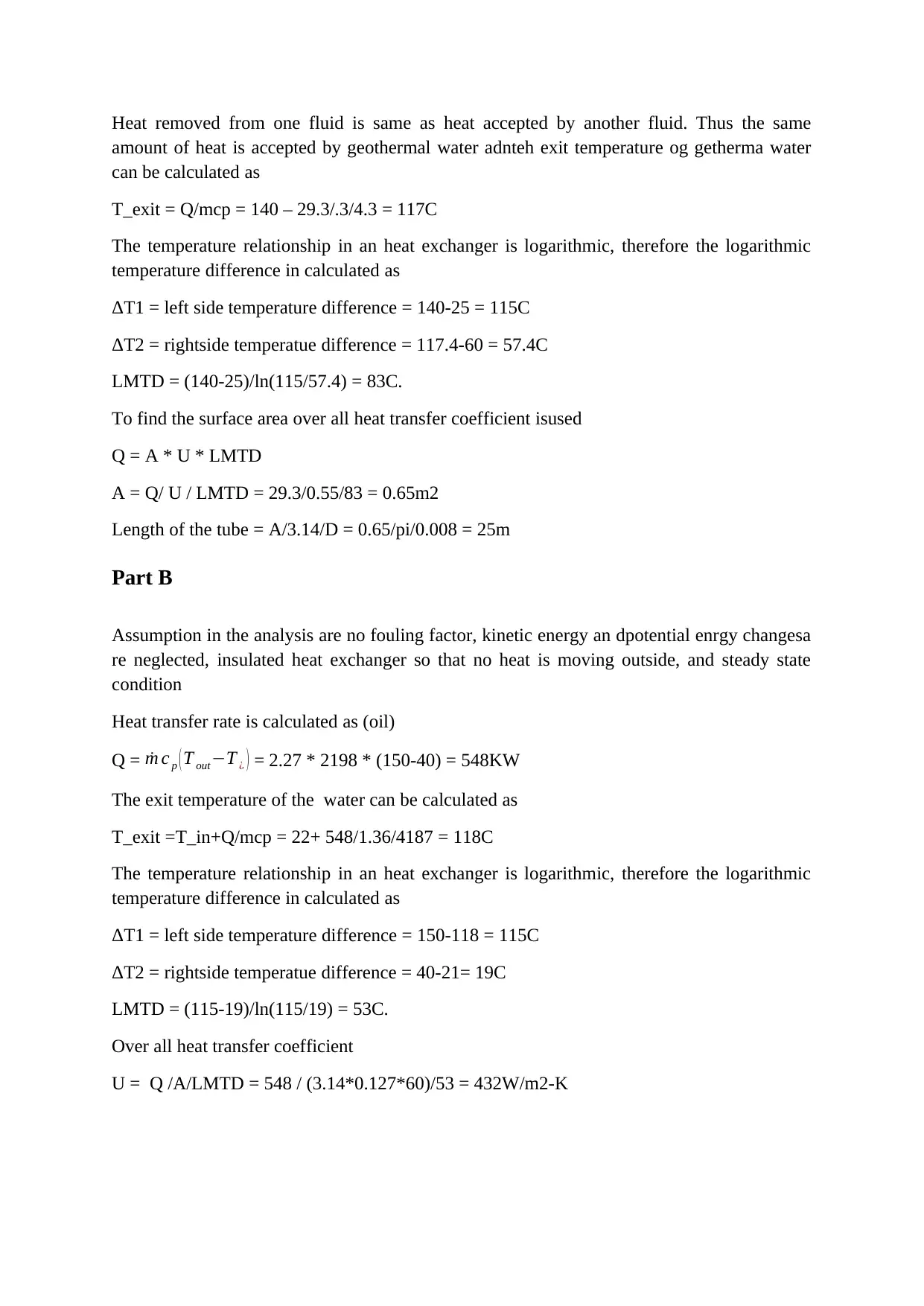
Assumption in the analysis are no fouling factor, kinetic energy an dpotential enrgy changesa
re neglected, insulated heat exchanger so that no heat is moving outside, and steady state
condition
The heat transfer taken place in the heat exchanger is calculated as absed on water
Q = ˙m c p ( T out−T ¿ ) = 0.2 * 4.18 * (60-25) = 29.3KW
Paraphrase This Document
Need a fresh take? Get an instant paraphrase of this document with our AI Paraphraser
Heat removed from one fluid is same as heat accepted by another fluid. Thus the same
amount of heat is accepted by geothermal water adnteh exit temperature og getherma water
can be calculated as
T_exit = Q/mcp = 140 – 29.3/.3/4.3 = 117C
The temperature relationship in an heat exchanger is logarithmic, therefore the logarithmic
temperature difference in calculated as
ΔT1 = left side temperature difference = 140-25 = 115C
ΔT2 = rightside temperatue difference = 117.4-60 = 57.4C
LMTD = (140-25)/ln(115/57.4) = 83C.
To find the surface area over all heat transfer coefficient isused
Q = A * U * LMTD
A = Q/ U / LMTD = 29.3/0.55/83 = 0.65m2
Length of the tube = A/3.14/D = 0.65/pi/0.008 = 25m
Part B
Assumption in the analysis are no fouling factor, kinetic energy an dpotential enrgy changesa
re neglected, insulated heat exchanger so that no heat is moving outside, and steady state
condition
Heat transfer rate is calculated as (oil)
Q = ˙m c p ( T out−T ¿ ) = 2.27 * 2198 * (150-40) = 548KW
The exit temperature of the water can be calculated as
T_exit =T_in+Q/mcp = 22+ 548/1.36/4187 = 118C
The temperature relationship in an heat exchanger is logarithmic, therefore the logarithmic
temperature difference in calculated as
ΔT1 = left side temperature difference = 150-118 = 115C
ΔT2 = rightside temperatue difference = 40-21= 19C
LMTD = (115-19)/ln(115/19) = 53C.
Over all heat transfer coefficient
U = Q /A/LMTD = 548 / (3.14*0.127*60)/53 = 432W/m2-K
Question 3
Part A
In this problem ther is no external heat transfer coefficient is given. Thus the heat transfer to
the surrounding air is by radiation
Heat transfer by radiation is calculated as
Q = ε A σ ( Ts4 −Ta4 )
= 0.72 * (3.14*0.0603*70) * 5.67 × 10−8 * ¿ ¿)
= 17.915KW
Part B
Efficiency of furnace = heat used for steam generaton
heat supplied = Qused
Qin = 0.8
Qin−Qlost
Qin = 0.8
Qin−17.915
Qin = 0.8, thre fore Qin = 85.97KW
Total energy used from the natural gas is
85.97 * 8760 * 3600 = 2711.3GJ
Total therm = 2711.3/0.1055=25699.6
Cost = 25699.6 * 1.128269.5 = 28269.55£
Part C
Energy balance
Heat transfer by conduction is same as heat transfer by radiation
Q_cond = Q_rad
2∗314∗k∗L∗(Ts−T )
ln (r 2
r 1 ) = ε A σ ( T 4 −Ta4 )
Solve for T
⊘ This is a preview!⊘
Do you want full access?
Subscribe today to unlock all pages.

Trusted by 1+ million students worldwide

2∗314∗0.038∗70∗((175+23)−T )
ln ( 80.15
30.15 ) = 0.72 * (3.14*0.0603*70) * 5.67 × 10−8 * ( T 4 −2914 )
T = 324.4K
Heat loss is = Q = ε A σ ( Ts4 −Ta4 )
= 0.72 * (3.14*0.0603*70) * 5.67 × 10−8 * ¿ ¿) = 2.083KW
Saved energy = Q_lost _old-Q_lost_new = 17.915KW-2.083KW = 15.832KW
Cost saved for an year =
15.832 * 8760 * 3600 = 499.27GJ
Total therm = 499.27/0.1055=4732.4
Cost saved in year= 4732.4* 1.128269.5 = 5339.1£
Coast saved per day = 5339.1/365 = 14.62£
Number of days needed to cover 750£ = 750/14.62=51.3days
Question 4
Part A
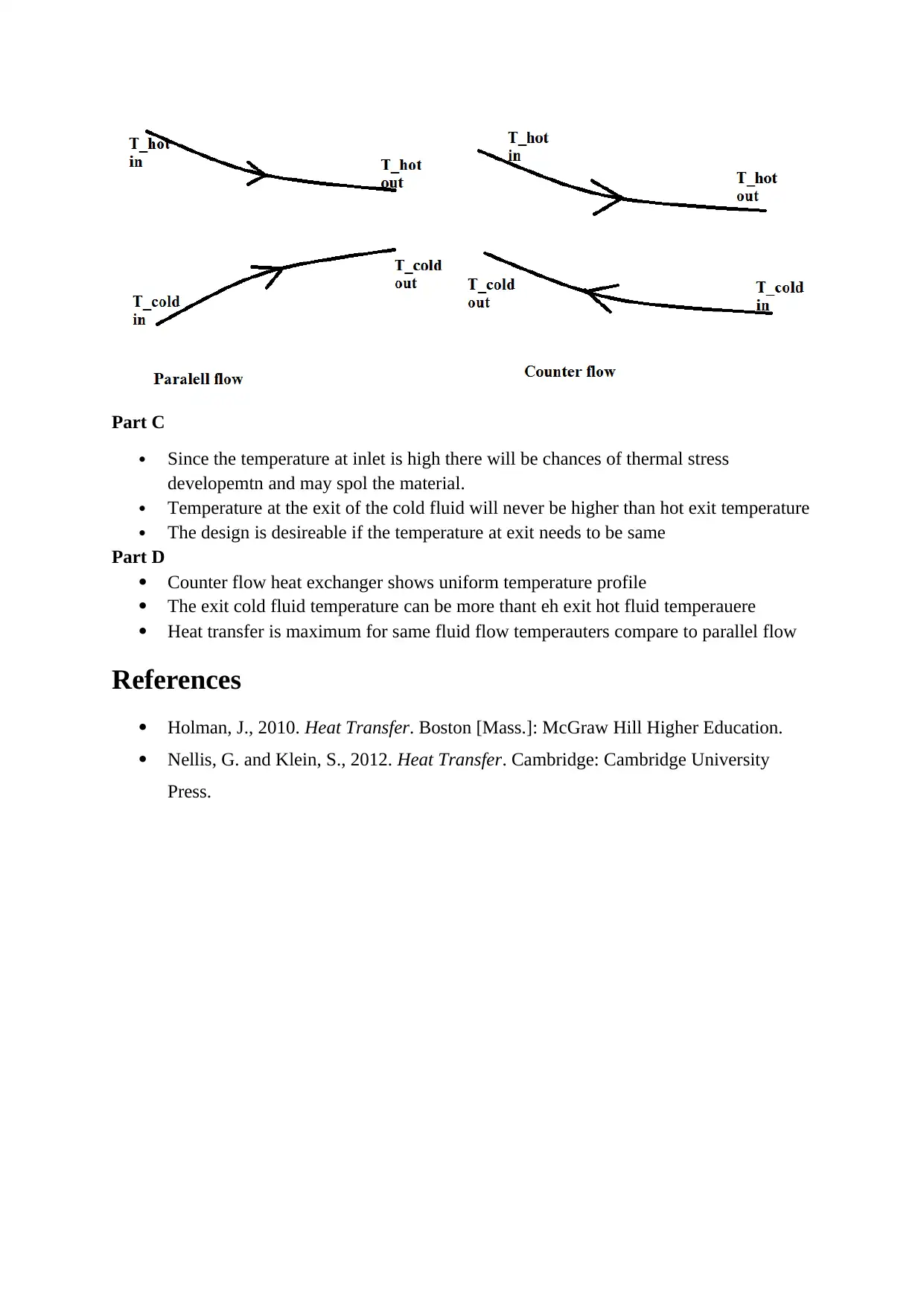
In parallel flow heat exchagr both fluid will flows in the same direction in thecounter flow the
fluids flow in oppsite direction.
Part B
Paraphrase This Document
Need a fresh take? Get an instant paraphrase of this document with our AI Paraphraser
Part C
Since the temperature at inlet is high there will be chances of thermal stress
developemtn and may spol the material.
Temperature at the exit of the cold fluid will never be higher than hot exit temperature
The design is desireable if the temperature at exit needs to be same
Part D
Counter flow heat exchanger shows uniform temperature profile
The exit cold fluid temperature can be more thant eh exit hot fluid temperauere
Heat transfer is maximum for same fluid flow temperauters compare to parallel flow
References
Holman, J., 2010. Heat Transfer. Boston [Mass.]: McGraw Hill Higher Education.
Nellis, G. and Klein, S., 2012. Heat Transfer. Cambridge: Cambridge University
Press.
1 out of 8
Your All-in-One AI-Powered Toolkit for Academic Success.
+13062052269
info@desklib.com
Available 24*7 on WhatsApp / Email
![[object Object]](/_next/static/media/star-bottom.7253800d.svg)
Unlock your academic potential
Copyright © 2020–2026 A2Z Services. All Rights Reserved. Developed and managed by ZUCOL.
