Mechanical Power Transmission System Design for a 3,500 lb Hoist Crane
VerifiedAdded on 2023/06/12
|12
|2293
|113
Project
AI Summary
This project outlines the design of a complete mechanical power transmission system for a hoist crane with a capacity of 3,500 lb and a lifting speed of 35 fpm. The design incorporates assumptions such as neglecting friction and central load application. The mechanism utilizes a wire rope electric crane design, focusing on components like the lifting motor, electromagnetic brake, and rising limiter. The project details the selection of transmission components, considering factors such as motor power, inverter type, and pneumatic lift options. Calculations are based on Newton's principle to determine mass and force relationships. The design summary emphasizes modularity and cost-effectiveness. The project concludes by addressing the challenges in balancing structural integrity and weight, particularly concerning horizontal movements and profile limitations. References to relevant research and standards are provided.

Hoist carne design
Student name:
Student Id:
Course:
Mentor:
Student name:
Student Id:
Course:
Mentor:
Paraphrase This Document
Need a fresh take? Get an instant paraphrase of this document with our AI Paraphraser
Contents
Design scope.........................................................................................................................................2
Assumptions and simplifications...........................................................................................................2
Design mechanism.................................................................................................................................3
Design and selection of transmission components.................................................................................5
3D drawing of complete system............................................................................................................6
2D drawings of each component...........................................................................................................6
Design calculations................................................................................................................................7
Design summary and cost considerations..............................................................................................7
Conclusion.............................................................................................................................................8
References.............................................................................................................................................8
Design scope
Design a complete mechanical power transmission system for a hoist with capacity of 3,500
lb and power of lifting with a speed of 35 fpm. All the dimensions shown in the drawing must
be identified from your design.
Assumptions and simplifications
The following assumptions are made during the design:
Friction is not taken into consideration.
No frictional power loss.
The load is acting at centre and there is no offset.
Design mechanism
Hoist cranes is a lifting equipment, wire rope electric cranes has a lessened structure, light
weight, minimal size, versatile parts, easy to work, et cetera., it can be presented
autonomously in the work Word steel, can in like manner be presented in the electric or
manual single column, twofold bar, cantilever, gantry and diverse cranes on the usage. Wire
rope electric lifts light weight, minimal size, decreased structure, variety particulars, smooth
undertaking. Well ordered guidelines to start the lifting motor, the lifting of the weight to the
fitting stature, and after that start running the motor to the staggering weight to the doled out
region, running the auto in the base of the single-shaft column walking. While walking, use a
motor to drive the wheels on the two sides of the auto (Soderberg, Olson, 2016). As the
walking speed is close to nothing, so the movement of the auto is generally no brake segment.
Brake is to rely upon the heaviness of the spring to the internal and outer plate weight; the
standard and the grinding handle like the landing of the use of electromagnet
electromagnetism after suction outside the circle and impact the outside plate to release.
⊘ This is a preview!⊘
Do you want full access?
Subscribe today to unlock all pages.
Trusted by 1+ million students worldwide
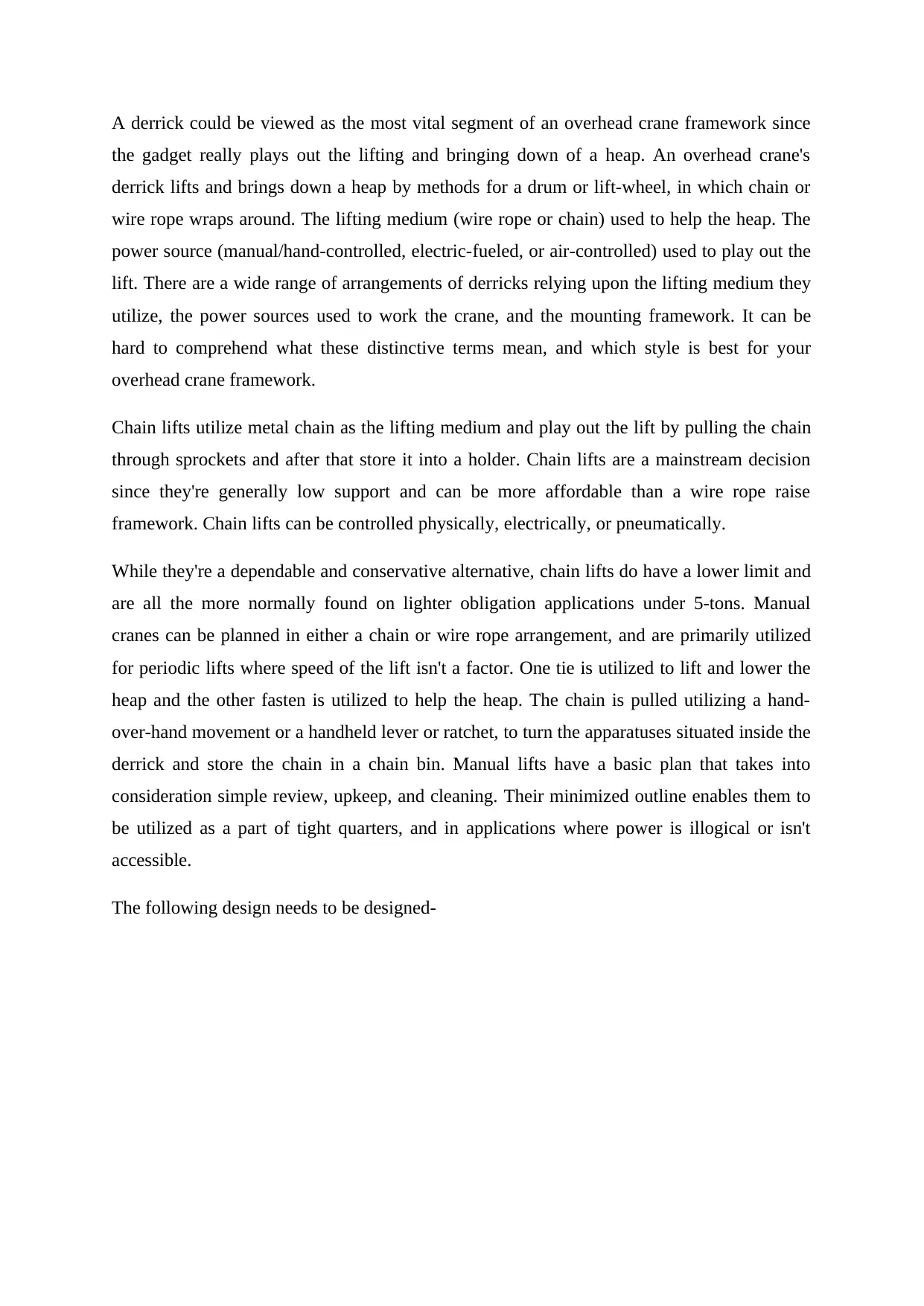
A derrick could be viewed as the most vital segment of an overhead crane framework since
the gadget really plays out the lifting and bringing down of a heap. An overhead crane's
derrick lifts and brings down a heap by methods for a drum or lift-wheel, in which chain or
wire rope wraps around. The lifting medium (wire rope or chain) used to help the heap. The
power source (manual/hand-controlled, electric-fueled, or air-controlled) used to play out the
lift. There are a wide range of arrangements of derricks relying upon the lifting medium they
utilize, the power sources used to work the crane, and the mounting framework. It can be
hard to comprehend what these distinctive terms mean, and which style is best for your
overhead crane framework.
Chain lifts utilize metal chain as the lifting medium and play out the lift by pulling the chain
through sprockets and after that store it into a holder. Chain lifts are a mainstream decision
since they're generally low support and can be more affordable than a wire rope raise
framework. Chain lifts can be controlled physically, electrically, or pneumatically.
While they're a dependable and conservative alternative, chain lifts do have a lower limit and
are all the more normally found on lighter obligation applications under 5-tons. Manual
cranes can be planned in either a chain or wire rope arrangement, and are primarily utilized
for periodic lifts where speed of the lift isn't a factor. One tie is utilized to lift and lower the
heap and the other fasten is utilized to help the heap. The chain is pulled utilizing a hand-
over-hand movement or a handheld lever or ratchet, to turn the apparatuses situated inside the
derrick and store the chain in a chain bin. Manual lifts have a basic plan that takes into
consideration simple review, upkeep, and cleaning. Their minimized outline enables them to
be utilized as a part of tight quarters, and in applications where power is illogical or isn't
accessible.
The following design needs to be designed-
Paraphrase This Document
Need a fresh take? Get an instant paraphrase of this document with our AI Paraphraser
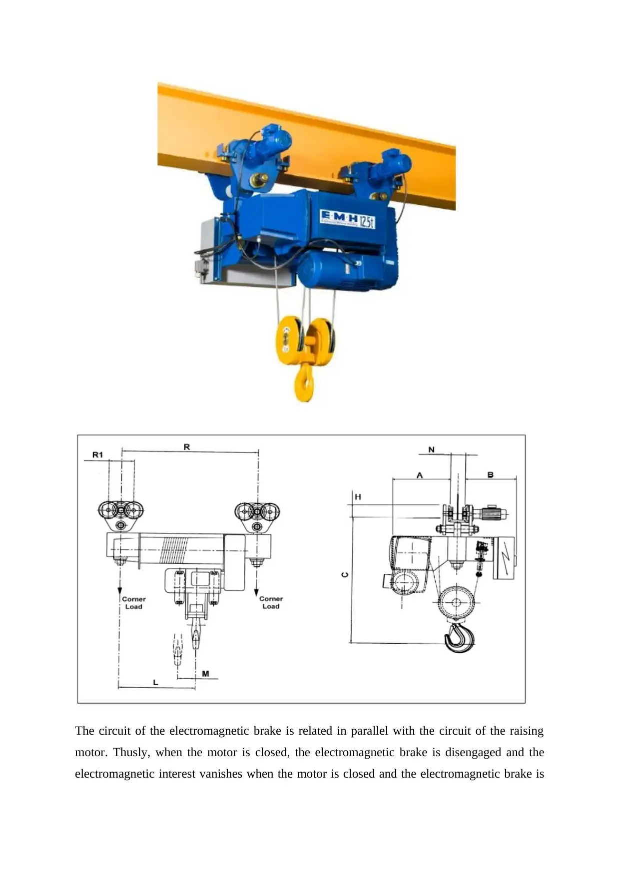
The circuit of the electromagnetic brake is related in parallel with the circuit of the raising
motor. Thusly, when the motor is closed, the electromagnetic brake is disengaged and the
electromagnetic interest vanishes when the motor is closed and the electromagnetic brake is
motor. Thusly, when the motor is closed, the electromagnetic brake is disengaged and the
electromagnetic interest vanishes when the motor is closed and the electromagnetic brake is
released, under the movement of the spring weight, the internal and outside circle solidly
pressed, accept the piece of braking (Na HH, Kim DJ, Choi, 2015). Electric derricks in the
lifting of articles to keep the climb past the purpose of control position caused by the mishap,
all things considered in the lower some part of the reel presented on the rising limiter. Exactly
when the store rises beyond what many would consider possible position, the weight plate
and the cut-off switch contact, slaughter the power, stop the weight continues rising. The
fitting is used to shield the impact from climbing past the limit position and thusly can't be
used a significant part of the time. Wire rope electric derricks has its central focuses also has
its deficiencies, over the traverse of the usage or should be attentive. Regardless, its purposes
of intrigue are more unmistakable than the lacks; it is in like manner a key bit of mechanical
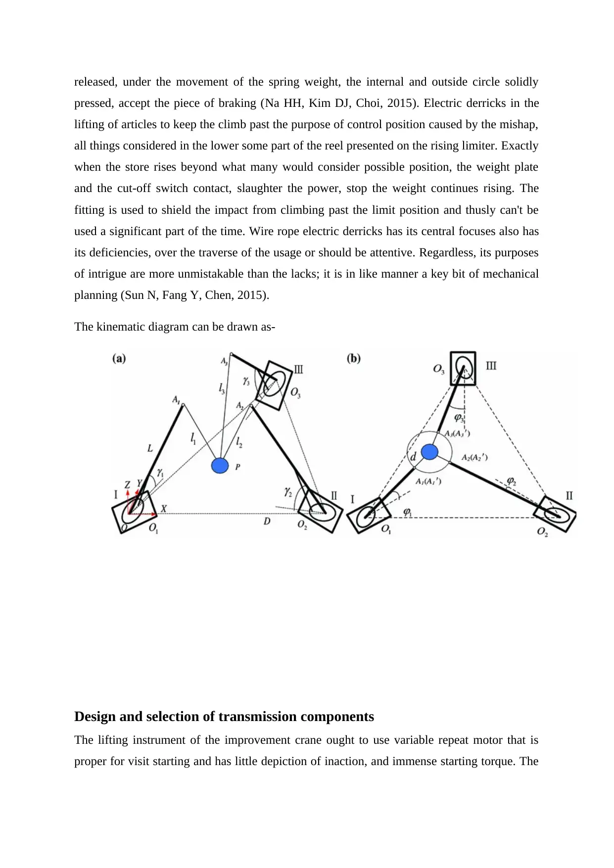
planning (Sun N, Fang Y, Chen, 2015).
The kinematic diagram can be drawn as-
Design and selection of transmission components
The lifting instrument of the improvement crane ought to use variable repeat motor that is
proper for visit starting and has little depiction of inaction, and immense starting torque. The
pressed, accept the piece of braking (Na HH, Kim DJ, Choi, 2015). Electric derricks in the
lifting of articles to keep the climb past the purpose of control position caused by the mishap,
all things considered in the lower some part of the reel presented on the rising limiter. Exactly
when the store rises beyond what many would consider possible position, the weight plate
and the cut-off switch contact, slaughter the power, stop the weight continues rising. The
fitting is used to shield the impact from climbing past the limit position and thusly can't be
used a significant part of the time. Wire rope electric derricks has its central focuses also has
its deficiencies, over the traverse of the usage or should be attentive. Regardless, its purposes
of intrigue are more unmistakable than the lacks; it is in like manner a key bit of mechanical
planning (Sun N, Fang Y, Chen, 2015).
The kinematic diagram can be drawn as-
Design and selection of transmission components
The lifting instrument of the improvement crane ought to use variable repeat motor that is
proper for visit starting and has little depiction of inaction, and immense starting torque. The
⊘ This is a preview!⊘
Do you want full access?
Subscribe today to unlock all pages.
Trusted by 1+ million students worldwide
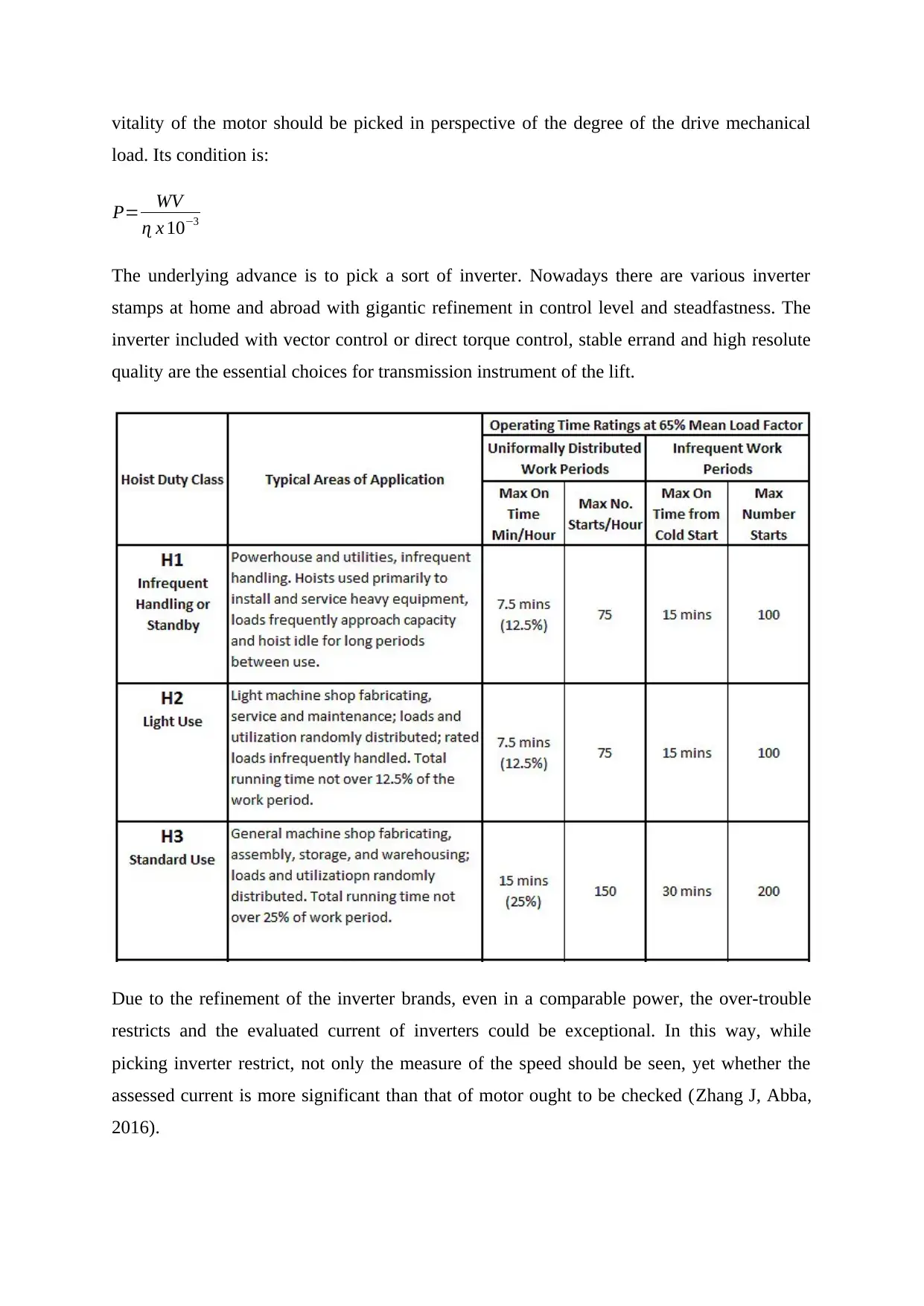
vitality of the motor should be picked in perspective of the degree of the drive mechanical
load. Its condition is:
P= WV
ɳ x 10−3
The underlying advance is to pick a sort of inverter. Nowadays there are various inverter
stamps at home and abroad with gigantic refinement in control level and steadfastness. The
inverter included with vector control or direct torque control, stable errand and high resolute
quality are the essential choices for transmission instrument of the lift.
Due to the refinement of the inverter brands, even in a comparable power, the over-trouble
restricts and the evaluated current of inverters could be exceptional. In this way, while
picking inverter restrict, not only the measure of the speed should be seen, yet whether the
assessed current is more significant than that of motor ought to be checked (Zhang J, Abba,
2016).
Paraphrase This Document
Need a fresh take? Get an instant paraphrase of this document with our AI Paraphraser
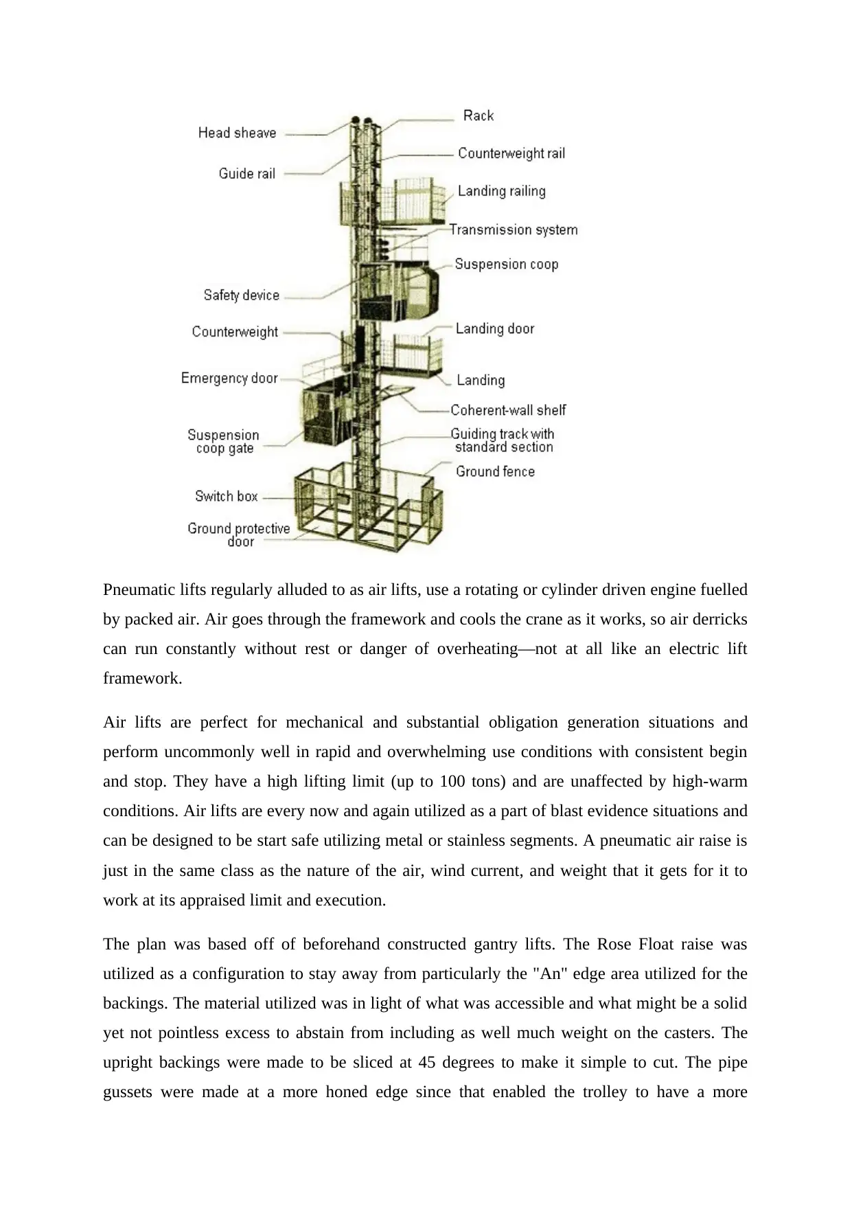
Pneumatic lifts regularly alluded to as air lifts, use a rotating or cylinder driven engine fuelled
by packed air. Air goes through the framework and cools the crane as it works, so air derricks
can run constantly without rest or danger of overheating—not at all like an electric lift
framework.
Air lifts are perfect for mechanical and substantial obligation generation situations and
perform uncommonly well in rapid and overwhelming use conditions with consistent begin
and stop. They have a high lifting limit (up to 100 tons) and are unaffected by high-warm
conditions. Air lifts are every now and again utilized as a part of blast evidence situations and
can be designed to be start safe utilizing metal or stainless segments. A pneumatic air raise is
just in the same class as the nature of the air, wind current, and weight that it gets for it to
work at its appraised limit and execution.
The plan was based off of beforehand constructed gantry lifts. The Rose Float raise was
utilized as a configuration to stay away from particularly the "An" edge area utilized for the
backings. The material utilized was in light of what was accessible and what might be a solid
yet not pointless excess to abstain from including as well much weight on the casters. The
upright backings were made to be sliced at 45 degrees to make it simple to cut. The pipe
gussets were made at a more honed edge since that enabled the trolley to have a more
extensive separation to move forward and backward. The material that was accessible was the
S10X25.4, which had just been cut at 10ft, the 4X4X3/16, the W6X12, random plate, and 3in
pipe.
The computations were done on the shaft, the upright (segment), and the caster mount. The
pillar traverse was 10ft with a Lb of 7ft giving a most extreme passable minute for this pillar
to be 45.98 kip*ft and a permissible point heap of 18.39 kips. The caster mount had a few
factors that would influence it and a most dire outcome imaginable was made and a limited
component investigation was done to ensure the mount would hold. The most pessimistic
scenario static was if the derrick was completely stacked (4000 lbs) and was being pushed by
somebody against something like a control. The caster moves off center applying a torque
around the caster mount alongside the power against the side by the individual pushing and
the power of the stacked pillar on the caster mount. The maximum pressure was about 17,500
psi which is underneath the maximum bowing worry of 0.6 Fy 27,600 psi. For any effect
stacking the power connected would be thought to be which the pillar can hold.
3D drawing of complete system
Need to be taken care from design team (AutoCAD or Solid Works)
2D drawings of each component
Need to be taken care from design team (AutoCAD or Solid Works)
Design calculations
The given data are as follows-
⊘ This is a preview!⊘
Do you want full access?
Subscribe today to unlock all pages.
Trusted by 1+ million students worldwide
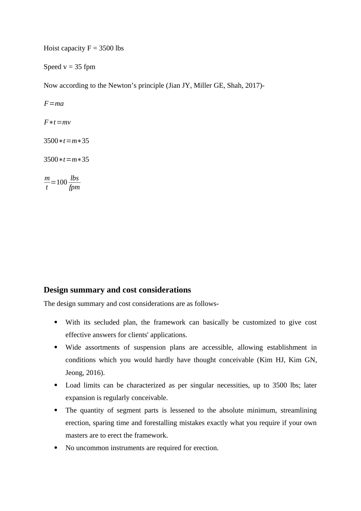
Hoist capacity F = 3500 lbs
Speed v = 35 fpm
Now according to the Newton’s principle (Jian JY, Miller GE, Shah, 2017)-
F=ma
F∗t=mv
3500∗t=m∗35
3500∗t=m∗35
m
t =100 lbs
fpm
Design summary and cost considerations
The design summary and cost considerations are as follows-
With its secluded plan, the framework can basically be customized to give cost
effective answers for clients' applications.
Wide assortments of suspension plans are accessible, allowing establishment in
conditions which you would hardly have thought conceivable (Kim HJ, Kim GN,
Jeong, 2016).
Load limits can be characterized as per singular necessities, up to 3500 lbs; later
expansion is regularly conceivable.
The quantity of segment parts is lessened to the absolute minimum, streamlining
erection, sparing time and forestalling mistakes exactly what you require if your own
masters are to erect the framework.
No uncommon instruments are required for erection.
Paraphrase This Document
Need a fresh take? Get an instant paraphrase of this document with our AI Paraphraser
Conclusion
The minutes are more noteworthy in the cantilever structure, and to follow the limits is to
build the extent of profile, the primary profile that meets the necessities. Then again, we take
note of that as expanding the profile of the structure additionally builds its span and thusly its
weight, making more prominent endeavours.
The most concerning issue has been taken in the improvement of work has been with
horizontals developments of the structure, which are those that point of confinement the span
of the profile. In the event that we think about the two structures when the y-hub is bigger in
outline structure, yet when the pivot "z" is more noteworthy in the cantilever structure.
References
Soderberg E, Olson L, Hsieh J. Crane Loads—Triple E Class and Beyond. InPorts 2016 2016
Jun (pp. 587-596).
Na HH, Kim DJ, Choi JS, Oh WJ, Park JW, Lee CH. Product Design and Manufacture on
Safety Hook and X-jog for application in Hoist and Crane. Journal of the Korean Society of
Marine Environment & Safety. 2015;21(1):91-6.
Sun N, Fang Y, Chen H, He B. Adaptive nonlinear crane control with load hoisting/lowering
and unknown parameters: Design and experiments. IEEE/ASME Transactions on
Mechatronics. 2015 Oct;20(5):2107-19.
Zhang J, Abba G. Influence of the Wind Load in the Trolley-Payload System with a Flexible
Hoist Rope. InAdvances in Robot Kinematics 2016 2018 (pp. 381-391). Springer, Cham.
Jian JY, Miller GE, Shah S. Preventing Human Error in Crane Operations: A Case Study of
Organizational and Design Elements. InProceedings of the Human Factors and Ergonomics
Society Annual Meeting 2017 Sep (Vol. 61, No. 1, pp. 1695-1699). Sage CA: Los Angeles,
CA: SAGE Publications.

Kim HJ, Kim GN, Jeong CK, Yoon YH, Jung YG, Huh SC. Hydraulic system design and
structural analysis of a BOP gantry crane. Journal of Marine Science and Technology. 2016
Jan 13.
structural analysis of a BOP gantry crane. Journal of Marine Science and Technology. 2016
Jan 13.
⊘ This is a preview!⊘
Do you want full access?
Subscribe today to unlock all pages.
Trusted by 1+ million students worldwide
1 out of 12
Your All-in-One AI-Powered Toolkit for Academic Success.
+13062052269
info@desklib.com
Available 24*7 on WhatsApp / Email
![[object Object]](/_next/static/media/star-bottom.7253800d.svg)
Unlock your academic potential
Copyright © 2020–2025 A2Z Services. All Rights Reserved. Developed and managed by ZUCOL.