Report on Industrial Visit to XXX Alloys, YYY: Mechanical Engineering
VerifiedAdded on 2023/01/06
|14
|2813
|32
Report
AI Summary
This report details an industrial visit to XXX Alloys, a manufacturing facility, providing insights into various departments and processes. The visit began with an overview of pattern making, discussing materials like wood, metal, and wax, along with the procedures for pattern selection and different pattern types. The report then explores allowances made in the pattern to compensate for shrinkage, draft, finishing, and other factors. The demand for patterns in sand casting is also discussed. The report further explains the roles of flask, sprue, core, riser, gate, runner, chaplets, and vents. The report then goes on to explore the testing and design department, including information on the American Foundry Society (AFS) and various testing methods such as impact, tensile, moisture content, grain fineness, MPI, and radiographic tests. The report provides detailed descriptions of each test and their applications in quality control and material analysis.
CHAPTER 1
INTRODUCTION
We went on an industrial visit on Tuesday (16.02.2016) to XXX Alloys, YYY. We
started from college by 9:30 by our college bus. We reached the industry by 11:00. We were split
into 3 batches and taken around the industry accompanied by a guide from the industry. There
were total of four departments consisting of pattern making, foundry, testing and planning,
finishing and testing of final component.
PATTERN MAKING
Pattern is the only copy of the model to be made. This pattern is made by many types of
materials like wood, plastics, araldite or many other chemical compositions.
MATERIALS USED
Materials are used for pattern making are wood, metal or plastics wax and plaster of Paris
are also used, but only for specialized applications. Mahogany is the most commonly used
material for patterns, primarily because it’s soft, light and easy to work, but also once properly
cured is about as stable as any wood available not subject to warping or curling. Once the pattern
is built the foundry does not want it changing shape. The downside is that it wears out fast and is
prone to moisture attack. Metal patterns are more long lasting and do not succumb to moisture,
but they are heavier and difficult to repair once damaged.
Wax patterns are used in a casting process called investment casting. A combination of
paraffin wax bee wax used for this purpose.
Plaster of Paris is usually used in making master dies and molds, as it gains hardness
quickly, with a lot of flexibility when in the setting stage.
Probably in Coimbatore super alloys traditional pattern making method of wooden
pattern is used. It would be better to the rate of production if other type of pattern such as wax
pattern is also used. It is suggested so because if there is a problem in any of the pattern it will be
difficult to repair incase of wooden patter but it will be convenient to repair the problem if it is a
wax pattern.
Paraphrase This Document
Need a fresh take? Get an instant paraphrase of this document with our AI Paraphraser
PROCEDURE FOR SELECTING A PATTERN
Invoice from customer is bought.
Pattern is already given by the customer or to be arranged by the company.
If pattern is not given by the customer diagram is bought.
Pattern is made as per the diagram of the customer.
Material is selected for pattern making.
Pattern is made as per the diagram.
It is then moved for moulding.
TYPES OF PATTERN
Single piece pattern- It is the replica of the desired casting. It is slightly larger than the
casting. These patterns maybe of wood, metal or plastic (hard plastic).
Match plate pattern, cope & drag pattern, lagged-up pattern, built up pattern, multi-piece
pattern, gated pattern, sweep pattern, skeleton pattern, shell pattern and loose piece pattern, left
and right hand pattern, follow board pattern, segmental patterns are some of the types of patterns.
CHAPTER 2
ALLOWANCES
To compensate for any dimensional and structural changes which will happen during the
casting or patterning process, allowances are usually made in the pattern.
CONTRACTION ALLOWANCES/ SHRINKAGE ALLOWANCES
• All most all cast metals shrink or contract volumetrically on cooling. The metal shrinkage
is of two types:
Liquid Shrinkage: it refers to the reduction in volume when the metal changes from
liquid state to solid state at the solidus temperature.
To account for this shrinkage; riser, which feed the liquid metal to the casting, are
provided in the mould.
Solid Shrinkage: it refers to the reduction in volume caused when metal loses
temperature in solid state.
To account for this, shrinkage allowance is provided on the patterns.
DRAFT/ TAPER ALLOWANCES
• By draft is meant the taper provided by the pattern maker on all vertical surfaces of the
pattern.
• So that it can be removed from the sand without tearing away the sides of the sand mould
and without excessive rapping by the moulder.
• In this case, till the pattern is completely lifted out, its sides will remain in contact with
the walls of the mould, thus tending to break it.
• Here, the moment the pattern lifting commences, all of its surfaces are well away from
the sand surface.
⊘ This is a preview!⊘
Do you want full access?
Subscribe today to unlock all pages.
Trusted by 1+ million students worldwide
• Thus the pattern can be removed without damaging the mould cavity.
FINISHING/ MACHINING ALLOWANCE
• The finish and accuracy achieved in sand casting are generally poor.
• When the casting is functionally required to be of good surface finish or dimensionally
accurate, it is generally achieved by subsequent machining.
• The amount of machining allowance to be provided for is affected by
• The method of moulding and casting used viz.
• Hand moulding or machine moulding
• Sand casting or metal mould casting.
• The size and shape of the casting
• The casting orientation
• The metal
• The degree of accuracy and finish required.
SHAKE/ RAPPING ALLOWANCE
• Before the withdrawal from the sand mould, the pattern is rapped all around the vertical
faces to enlarge the mould cavity slightly, which facilitate its removal.
• Since it enlarges the final casting made, it is desirable that the original pattern dimension
should be reduced to account for this increase.
• There is no sure way of quantifying this allowance, since it is highly dependent on the
foundry personnel practice involved.
It is a negative allowance and is to be applied only to those dimensions that are parallel to the
parting plane.
Paraphrase This Document
Need a fresh take? Get an instant paraphrase of this document with our AI Paraphraser
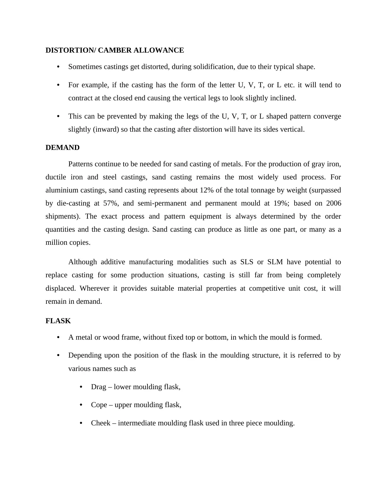
DISTORTION/ CAMBER ALLOWANCE
• Sometimes castings get distorted, during solidification, due to their typical shape.
• For example, if the casting has the form of the letter U, V, T, or L etc. it will tend to
contract at the closed end causing the vertical legs to look slightly inclined.
• This can be prevented by making the legs of the U, V, T, or L shaped pattern converge
slightly (inward) so that the casting after distortion will have its sides vertical.
DEMAND
Patterns continue to be needed for sand casting of metals. For the production of gray iron,
ductile iron and steel castings, sand casting remains the most widely used process. For
aluminium castings, sand casting represents about 12% of the total tonnage by weight (surpassed
by die-casting at 57%, and semi-permanent and permanent mould at 19%; based on 2006
shipments). The exact process and pattern equipment is always determined by the order
quantities and the casting design. Sand casting can produce as little as one part, or many as a
million copies.
Although additive manufacturing modalities such as SLS or SLM have potential to
replace casting for some production situations, casting is still far from being completely
displaced. Wherever it provides suitable material properties at competitive unit cost, it will
remain in demand.
FLASK
• A metal or wood frame, without fixed top or bottom, in which the mould is formed.
• Depending upon the position of the flask in the moulding structure, it is referred to by
various names such as
• Drag – lower moulding flask,
• Cope – upper moulding flask,
• Cheek – intermediate moulding flask used in three piece moulding.
SPRUE
The passage through which the molten metal, from the pouring basin, reaches the
mould cavity. In many cases it controls the flow of metal into the mould.
CORE
• A separate part of the mould, made of sand and generally baked, which is used to create
openings and various shaped cavities in the castings.
RISER
• A column of molten metal placed in the mould to feed the castings as it shrinks and
solidifies.
• Also known as “feed head”.
GATE
A channel through which the molten metal enters the mould cavity.
RUNNER
• The channel through which the molten metal is carried from the sprue to the gate.
CHAPLETS
Chaplets are used to support the cores inside the mould cavity to take care of its own
weight and overcome the metallostatic force.
VENT
A small opening in the mould to facilitate escape of air and gases.
FUNCTIONS OF PATTERN MAKING
1. A pattern prepares a mould cavity for the purpose of making a casting.
2. A pattern may contain projections known as core prints if the casting requires a core and need
to be made hollow.
⊘ This is a preview!⊘
Do you want full access?
Subscribe today to unlock all pages.
Trusted by 1+ million students worldwide

3. Runner, gates, and risers used for feeding molten metal in the mould cavity may form a part of
the pattern.
4. Patterns properly made and having finished and smooth surfaces reduce casting defects.
5. A properly constructed pattern minimizes the overall cost of the castings.
the pattern.
4. Patterns properly made and having finished and smooth surfaces reduce casting defects.
5. A properly constructed pattern minimizes the overall cost of the castings.
Paraphrase This Document
Need a fresh take? Get an instant paraphrase of this document with our AI Paraphraser
CHAPTER 3
TESTING AND DESIGN DEPARTMENT
There are totally two standard books used in foundry-
1. American foundry society (AFS).
2. European foundry association (EFA).
AMERICAN FOUNDRY SOCIETY
The American Foundry Society is the leading U.S. based metal casting society, assisting
member companies (metal casting facilities, die casters and industry suppliers) and individuals to
effectively manage their production operations, profitably market their products and services and
equitably manage their employees. The American Foundry Society also promotes the interests of
the metal casting industry before the legislative and executive branches of the federal
government. With the direction of its volunteer committee structure, the professional staff of the
American Foundry Society provides support in the areas of technology, management and
education to further the economic progress of the metal casting industry.
DIFFERENT TESTINGS DONE ON THE MATERIAL TO BE USED
Impact test, tensile test, moisture content test, grain fitness test, MPI test, radio graphic
test, ultra sonic test, LP test.
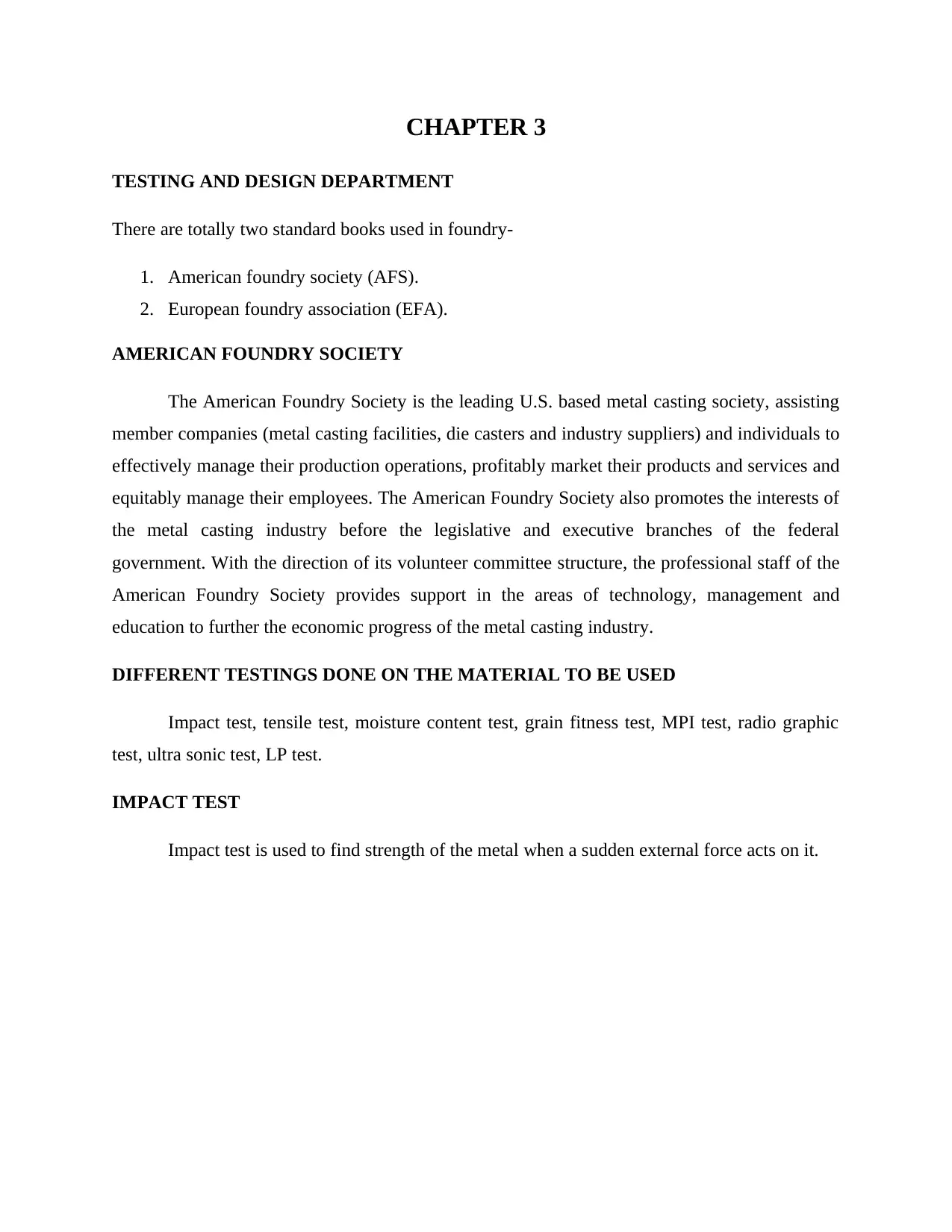
IMPACT TEST
Impact test is used to find strength of the metal when a sudden external force acts on it.
TESTING AND DESIGN DEPARTMENT
There are totally two standard books used in foundry-
1. American foundry society (AFS).
2. European foundry association (EFA).
AMERICAN FOUNDRY SOCIETY
The American Foundry Society is the leading U.S. based metal casting society, assisting
member companies (metal casting facilities, die casters and industry suppliers) and individuals to
effectively manage their production operations, profitably market their products and services and
equitably manage their employees. The American Foundry Society also promotes the interests of
the metal casting industry before the legislative and executive branches of the federal
government. With the direction of its volunteer committee structure, the professional staff of the
American Foundry Society provides support in the areas of technology, management and
education to further the economic progress of the metal casting industry.
DIFFERENT TESTINGS DONE ON THE MATERIAL TO BE USED
Impact test, tensile test, moisture content test, grain fitness test, MPI test, radio graphic
test, ultra sonic test, LP test.
IMPACT TEST
Impact test is used to find strength of the metal when a sudden external force acts on it.
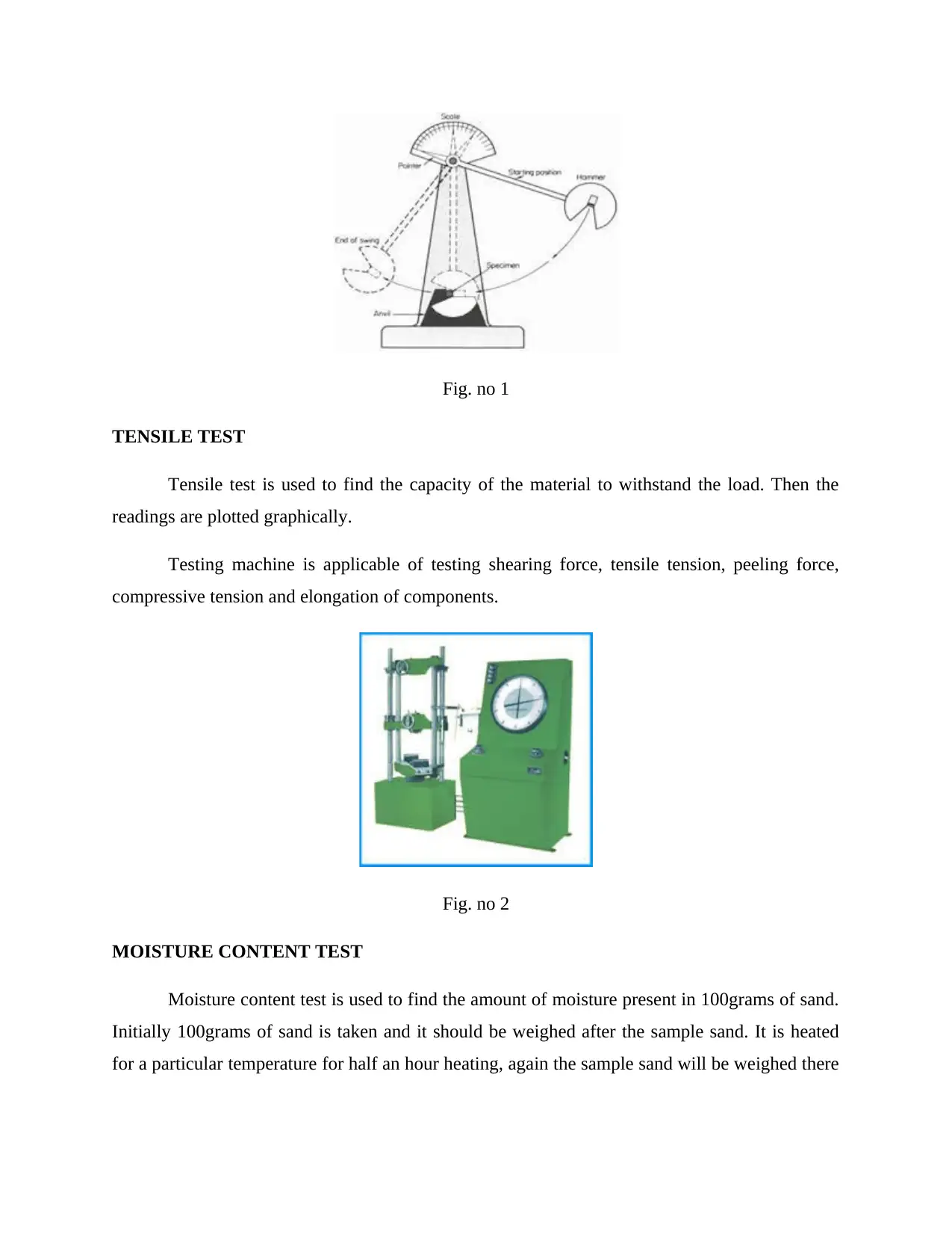
Fig. no 1
TENSILE TEST
Tensile test is used to find the capacity of the material to withstand the load. Then the
readings are plotted graphically.
Testing machine is applicable of testing shearing force, tensile tension, peeling force,
compressive tension and elongation of components.
Fig. no 2
MOISTURE CONTENT TEST
Moisture content test is used to find the amount of moisture present in 100grams of sand.
Initially 100grams of sand is taken and it should be weighed after the sample sand. It is heated
for a particular temperature for half an hour heating, again the sample sand will be weighed there
⊘ This is a preview!⊘
Do you want full access?
Subscribe today to unlock all pages.
Trusted by 1+ million students worldwide
will be a weight difference between initial and final. That difference shows the moisture content
in 100 grams of sample sand.
GRAIN FINENESS TEST
This test is used to find the size of the sand, with the help of grain fineness tester. The
major component is sleeves it consist number of different size of sleeves mounted one above the
other. The sample sand is poured at top of the sleeves due to external vibration. The sand gets
filtered layer by layer and finally we get how much amount of sand is deposited in each sleeve.
The sand particle is measured in microns.
MPI TEST
MPI test is used to find any crack inside the job with the help of electrode, ultra violet
light and fluorescent in this test we can find defect upto 7mm. When the defect is located above
7mm it will be difficult to find in this test what type of current we are supplying is important
Alternating current (AC) is commonly used to defect surface discontinuities.
The presence of a surface or subsurface discontinuity in the material allows the magnetic flux to
leak, since air cannot support as much magnetic field per unit volume as metals. Ferrous iron
particles are then applied to the part. The particles may be dry or in a wet suspension. If an area
of flux leakage is present, the particles will be attracted to this area.
The particles will build up at the area of leakage and form what is known as an
indication. The induction can then be evaluated to determine what it is, what may have caused it,
and what action should be taken, if any.
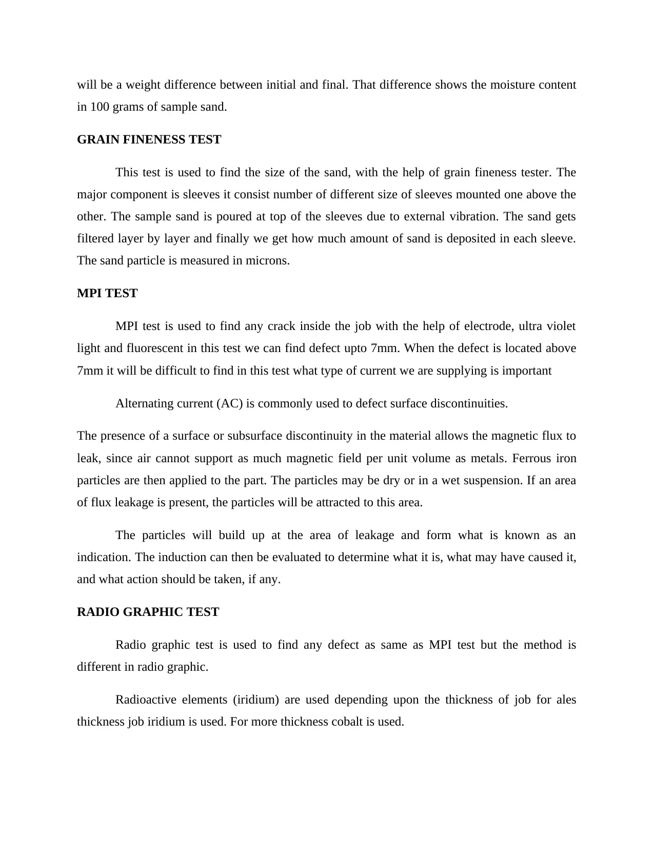
RADIO GRAPHIC TEST
Radio graphic test is used to find any defect as same as MPI test but the method is
different in radio graphic.
Radioactive elements (iridium) are used depending upon the thickness of job for ales
thickness job iridium is used. For more thickness cobalt is used.
in 100 grams of sample sand.
GRAIN FINENESS TEST
This test is used to find the size of the sand, with the help of grain fineness tester. The
major component is sleeves it consist number of different size of sleeves mounted one above the
other. The sample sand is poured at top of the sleeves due to external vibration. The sand gets
filtered layer by layer and finally we get how much amount of sand is deposited in each sleeve.
The sand particle is measured in microns.
MPI TEST
MPI test is used to find any crack inside the job with the help of electrode, ultra violet
light and fluorescent in this test we can find defect upto 7mm. When the defect is located above
7mm it will be difficult to find in this test what type of current we are supplying is important
Alternating current (AC) is commonly used to defect surface discontinuities.
The presence of a surface or subsurface discontinuity in the material allows the magnetic flux to
leak, since air cannot support as much magnetic field per unit volume as metals. Ferrous iron
particles are then applied to the part. The particles may be dry or in a wet suspension. If an area
of flux leakage is present, the particles will be attracted to this area.
The particles will build up at the area of leakage and form what is known as an
indication. The induction can then be evaluated to determine what it is, what may have caused it,
and what action should be taken, if any.
RADIO GRAPHIC TEST
Radio graphic test is used to find any defect as same as MPI test but the method is
different in radio graphic.
Radioactive elements (iridium) are used depending upon the thickness of job for ales
thickness job iridium is used. For more thickness cobalt is used.
Paraphrase This Document
Need a fresh take? Get an instant paraphrase of this document with our AI Paraphraser
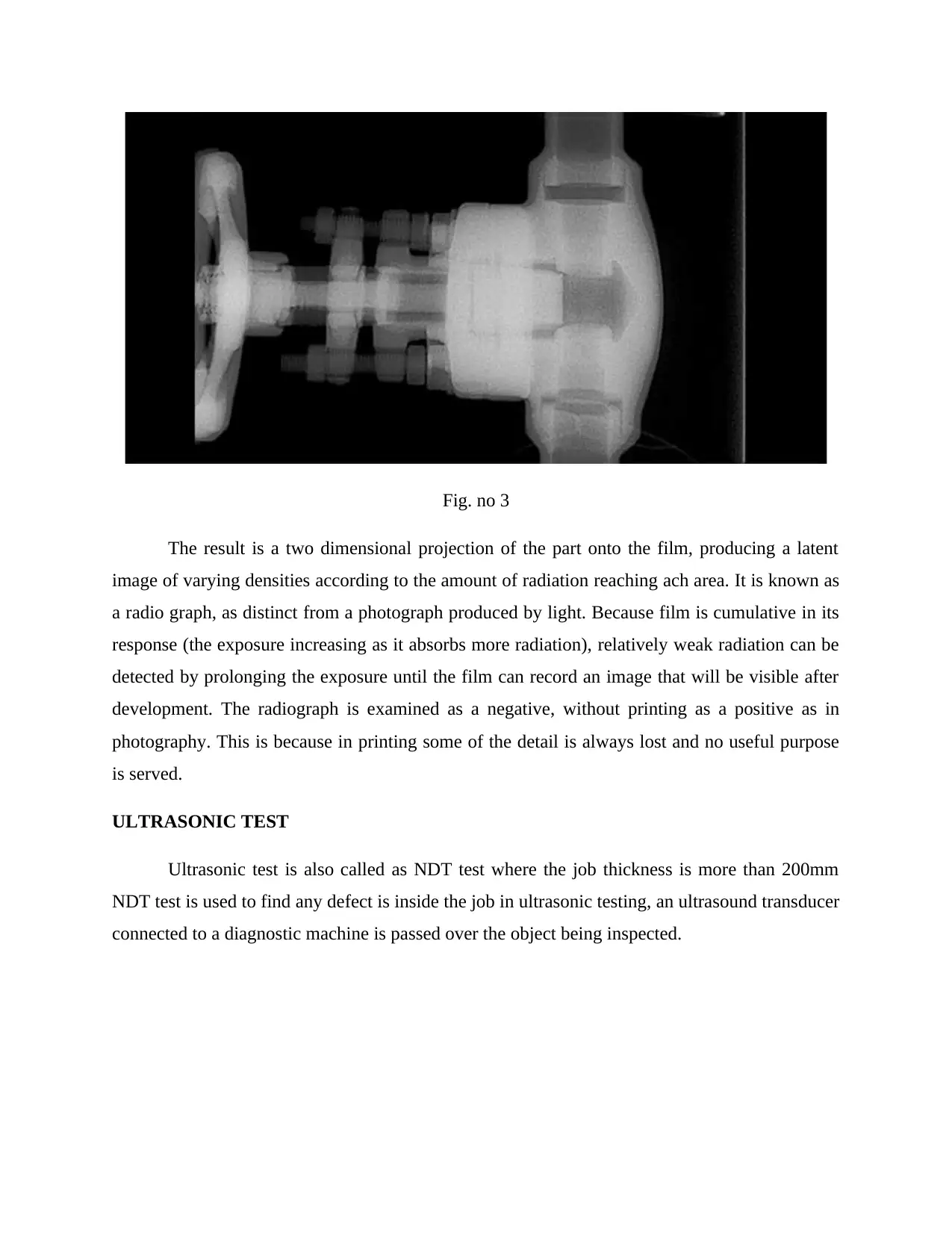
Fig. no 3
The result is a two dimensional projection of the part onto the film, producing a latent
image of varying densities according to the amount of radiation reaching ach area. It is known as
a radio graph, as distinct from a photograph produced by light. Because film is cumulative in its
response (the exposure increasing as it absorbs more radiation), relatively weak radiation can be
detected by prolonging the exposure until the film can record an image that will be visible after
development. The radiograph is examined as a negative, without printing as a positive as in
photography. This is because in printing some of the detail is always lost and no useful purpose
is served.
ULTRASONIC TEST
Ultrasonic test is also called as NDT test where the job thickness is more than 200mm
NDT test is used to find any defect is inside the job in ultrasonic testing, an ultrasound transducer
connected to a diagnostic machine is passed over the object being inspected.
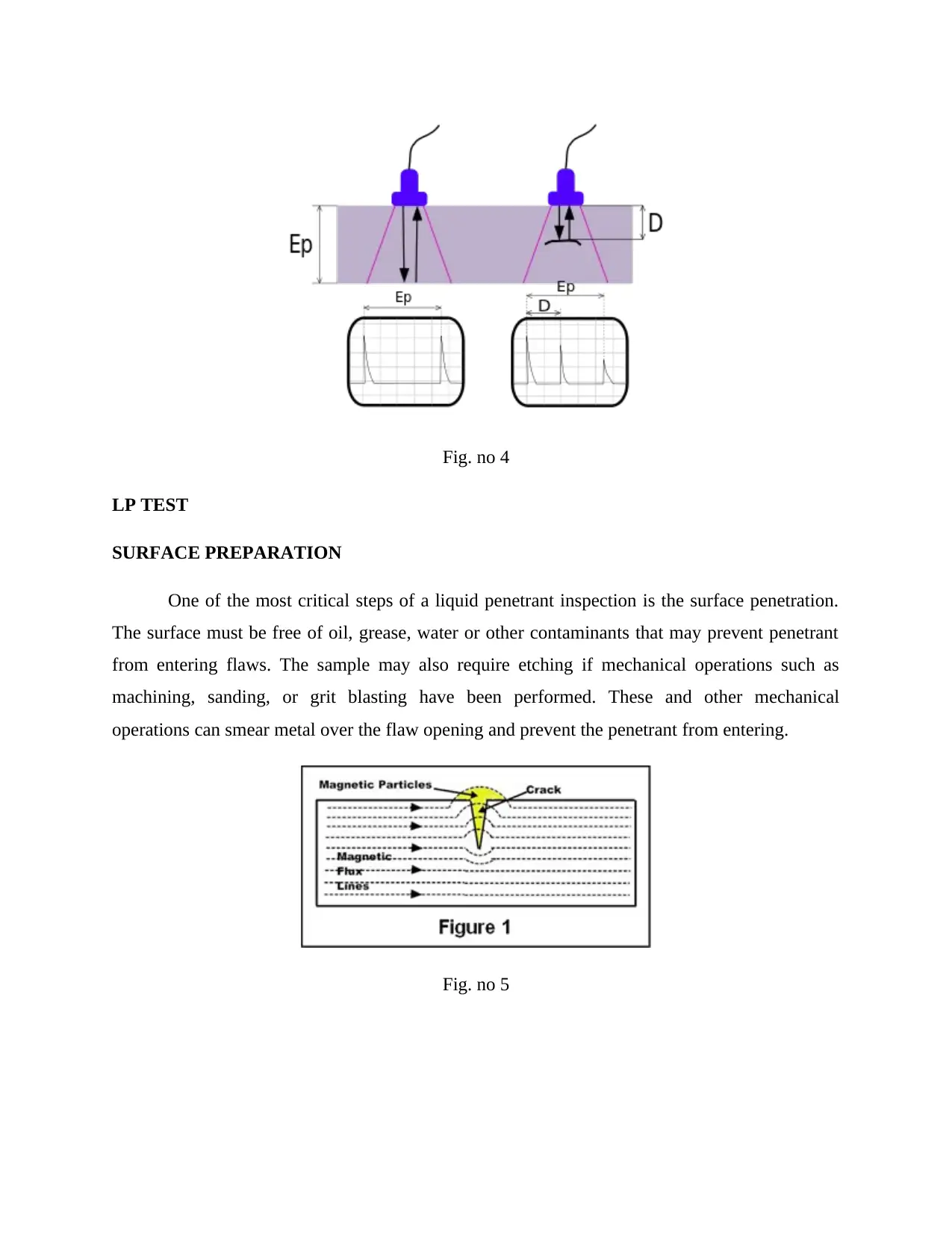
Fig. no 4
LP TEST
SURFACE PREPARATION
One of the most critical steps of a liquid penetrant inspection is the surface penetration.
The surface must be free of oil, grease, water or other contaminants that may prevent penetrant
from entering flaws. The sample may also require etching if mechanical operations such as
machining, sanding, or grit blasting have been performed. These and other mechanical
operations can smear metal over the flaw opening and prevent the penetrant from entering.
Fig. no 5
⊘ This is a preview!⊘
Do you want full access?
Subscribe today to unlock all pages.
Trusted by 1+ million students worldwide
1 out of 14
Your All-in-One AI-Powered Toolkit for Academic Success.
+13062052269
info@desklib.com
Available 24*7 on WhatsApp / Email
![[object Object]](/_next/static/media/star-bottom.7253800d.svg)
Unlock your academic potential
Copyright © 2020–2026 A2Z Services. All Rights Reserved. Developed and managed by ZUCOL.