MECH202 Fluid Mechanics Lab: Metacentric Height Experiment Report
VerifiedAdded on 2023/01/13
|17
|2098
|53
Practical Assignment
AI Summary
This assignment presents an experiment to determine the metacentric height of a floating object, comparing experimental results with theoretical values. The experiment utilizes a pontoon to analyze the metacentric height, employing geometric dimensions for theoretical calculations. The procedure includes analyzing factors that may affect the accuracy of the results. The report covers the objective, theory, equipment, experimental procedure, and results, including tables and plots of metacentric height versus the center of gravity and heal angle. Discussions include the impact of the center of gravity on metacentric height, discrepancies in theoretical and experimental results, potential ignored influences, and real-world applications such as ship design. The assignment concludes with a bibliography of relevant sources.

METACENTRIC HEIGHT 1
METACENTRIC HEIGHT
By Name
Course
Instructor
Institution
Location
Date
METACENTRIC HEIGHT
By Name
Course
Instructor
Institution
Location
Date
Paraphrase This Document
Need a fresh take? Get an instant paraphrase of this document with our AI Paraphraser
METACENTRIC HEIGHT 2
TOPIC: METACENTRIC HEIGHT
ABSTRACT
For this experiment, a study of the metacentric height of some floating object in water
will be conducted. A floating pontoon will be employed with vertical height to help analyses the
scenario. The dimensions of geometry will be employed to obtain the theoretical values of the
height of metacentre. The experimental procedure will as well help to set the experiment in the
right way to enable getting the correct results. The factors which hinder the accuracy of the
experimental results will be fully analyzed.
METACENTRIC HEIGHT 3
Table of Contents
TOPIC..............................................................................................................................................2
ABSTRACT....................................................................................................................................2
Table of Contents.............................................................................................................................3
List of figures...................................................................................................................................3
OBJECTIVE....................................................................................................................................4
THEORY/INTRODUCTION..........................................................................................................4
EQUIPMENT USED IN EXPERIMENT.......................................................................................7
EXPERIMENTAL PROCEDURE..................................................................................................8
RESULT OF EXPERIMENT..........................................................................................................9
A plot of CoG vs Metacentric Height............................................................................................12
Extrapolating GM for zero Heal Angle.........................................................................................12
Comment on Effect of CoG on GM..............................................................................................14
Reasons for Discrepancies in Theoretical and Experimental Results...........................................14
Any Potential Influences That were Ignored.................................................................................15
Real World Application of Metacentric Height.............................................................................15
Bibliography..................................................................................................................................16
List of figures
Figure 1: Showing metacentric height.............................................................................................5
Figure 2: Showing Calculation of Metacentric Height....................................................................6
Figure 3: Showing Metacentric height determination apparatus.....................................................8
Figure 4: Plot of Metacentric height vs CoG.................................................................................12
Figure 5: Heal Angle Vs Metacentric Height (Case-1).................................................................13
Figure 6: Heal Angle Vs Metacentric Height (Case-2).................................................................13
⊘ This is a preview!⊘
Do you want full access?
Subscribe today to unlock all pages.
Trusted by 1+ million students worldwide
METACENTRIC HEIGHT 4
OBJECTIVE
The main objective of this experiment is to obtain the metacentric height of a floating
object, the results will be compared with the theoretical values. Some key equations for obtaining
metacentric heights will be employed in this experiment. Impact of the location of the centre of
gravity will be reviewed on metacentric height as well as its relation to the stability of the
float.The values of GM for zero heal angle will be obtained via extrapolation. Again, the graph
for heal angle and metacentric heights will be drawn.
THEORY/INTRODUCTION
Metacentric is very important in determining the stability of an object. Actually, it is an
intersection point which is vertical to the axis passing via the original centre of gravity (CoG)
and for floating object it is known as centre of buoyancy (CoB) and the line that is vertical to the
axis through the new CoG or CoB after the object has been displaced [1]. In most cases when the
object is twisted in water its CoB always shift [2]. And in some cases, there is a point which
always remains un-displaced during this process and this point lies in the line which is vertical to
the buoyancy. Therefore this point which does not change is what is known as the metacentre
[3]. This can be better explained using the below diagram;
Paraphrase This Document
Need a fresh take? Get an instant paraphrase of this document with our AI Paraphraser
METACENTRIC HEIGHT 5
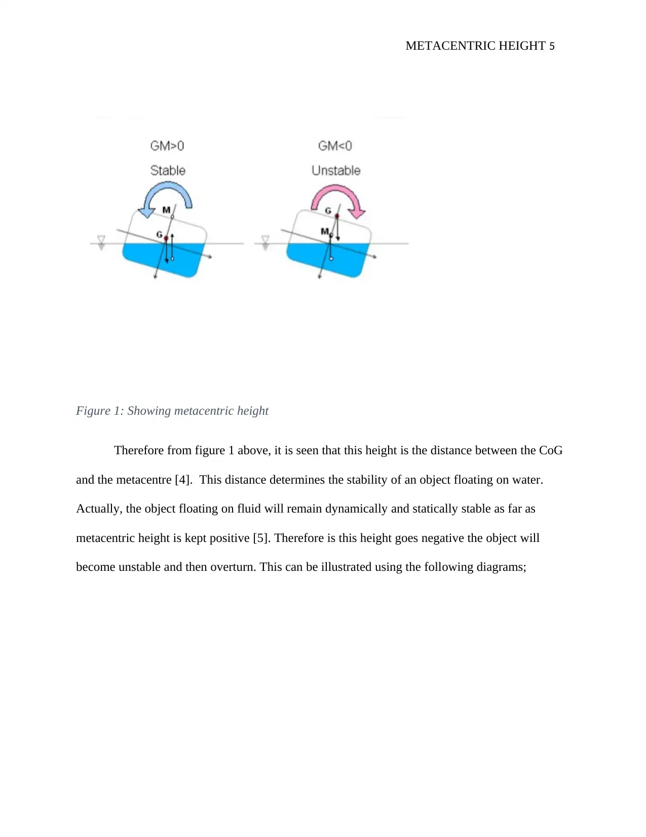
Figure 1: Showing metacentric height
Therefore from figure 1 above, it is seen that this height is the distance between the CoG
and the metacentre [4]. This distance determines the stability of an object floating on water.
Actually, the object floating on fluid will remain dynamically and statically stable as far as
metacentric height is kept positive [5]. Therefore is this height goes negative the object will
become unstable and then overturn. This can be illustrated using the following diagrams;
METACENTRIC HEIGHT 6
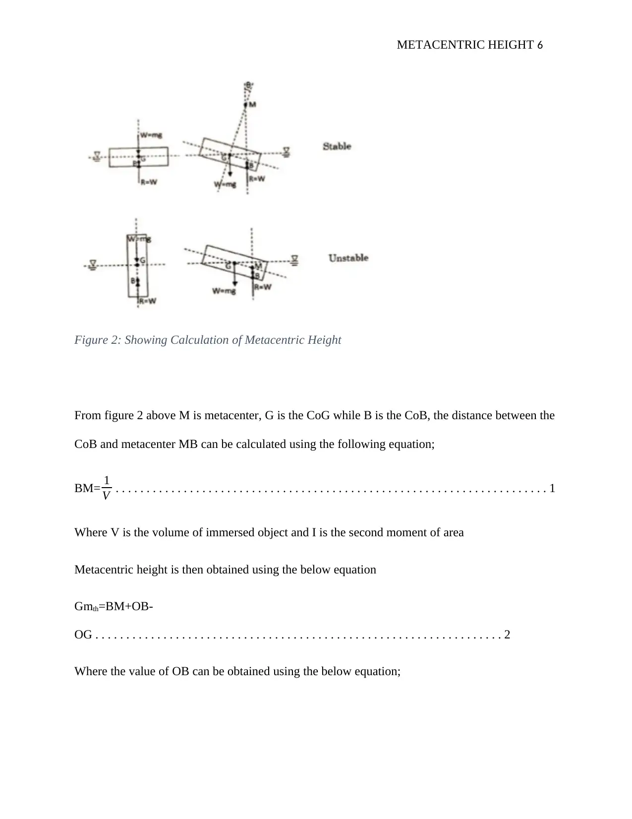
Figure 2: Showing Calculation of Metacentric Height
From figure 2 above M is metacenter, G is the CoG while B is the CoB, the distance between the
CoB and metacenter MB can be calculated using the following equation;
BM= 1
V . . . . . . . . . . . . . . . . . . . . . . . . . . . . . . . . . . . . . . . . . . . . . . . . . . . . . . . . . . . . . . . . . . . . . . 1
Where V is the volume of immersed object and I is the second moment of area
Metacentric height is then obtained using the below equation
Gmth=BM+OB-
OG . . . . . . . . . . . . . . . . . . . . . . . . . . . . . . . . . . . . . . . . . . . . . . . . . . . . . . . . . . . . . . . . . . 2
Where the value of OB can be obtained using the below equation;
⊘ This is a preview!⊘
Do you want full access?
Subscribe today to unlock all pages.
Trusted by 1+ million students worldwide
METACENTRIC HEIGHT 7
OB= V
2bd . . . . . . . . . . . . . . . . . . . . . . . . . . . . . . . . . . . . . . . . . . . . . . . . . . . . . . . . . . . . . . . . . . . . . .
. . . . . . 3
Where b is the breadth of the object floating and d is the immersed depth for the object floating
Determination of the metacentric height through experiment needs tilt angle which corresponds
to a particular inclination weight. Hence, the stable position of a floating object will be
deliberately disturbed and then it will be allowed to tilt. The height (metacenter) will then be
obtained using the below equation.
GMexp = px
Wtanθ . . . . . . . . . . . . . . . . . . . . . . . . . . . . . . . . . . . . . . . . . . . . . . . . . . . . . . . . . . . . . . . . .
. . 4
Where W is the total mass, p is the inclination mass, x is the offset location of inclination mass
and θ is the tilt angle.
EQUIPMENT USED IN THE EXPERIMENT
The following components are used in conducting this experiment together with a water tank
where the regular pontoon is put.
1. Pump line
2. Inclined weight
3. Line scale
4. Angular scale
5. Vertical mast
Paraphrase This Document
Need a fresh take? Get an instant paraphrase of this document with our AI Paraphraser
METACENTRIC HEIGHT 8
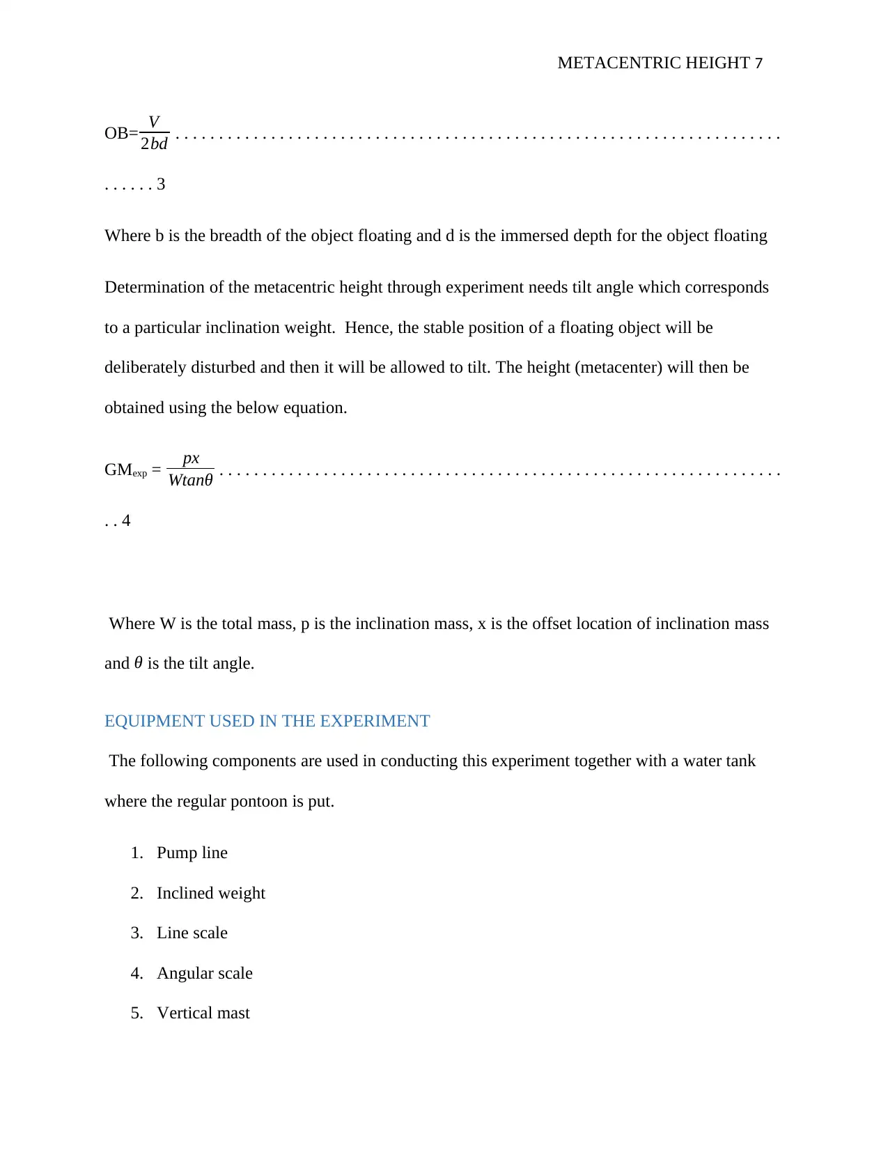
And the experimental setup can be illustrated using the following diagram;
Figure 3: Showing Metacentric height determination apparatus.
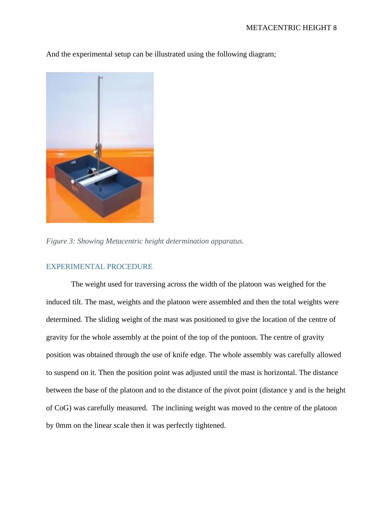
EXPERIMENTAL PROCEDURE
The weight used for traversing across the width of the platoon was weighed for the
induced tilt. The mast, weights and the platoon were assembled and then the total weights were
determined. The sliding weight of the mast was positioned to give the location of the centre of
gravity for the whole assembly at the point of the top of the pontoon. The centre of gravity
position was obtained through the use of knife edge. The whole assembly was carefully allowed
to suspend on it. Then the position point was adjusted until the mast is horizontal. The distance
between the base of the platoon and to the distance of the pivot point (distance y and is the height
of CoG) was carefully measured. The inclining weight was moved to the centre of the platoon
by 0mm on the linear scale then it was perfectly tightened.
And the experimental setup can be illustrated using the following diagram;
Figure 3: Showing Metacentric height determination apparatus.
EXPERIMENTAL PROCEDURE
The weight used for traversing across the width of the platoon was weighed for the
induced tilt. The mast, weights and the platoon were assembled and then the total weights were
determined. The sliding weight of the mast was positioned to give the location of the centre of
gravity for the whole assembly at the point of the top of the pontoon. The centre of gravity
position was obtained through the use of knife edge. The whole assembly was carefully allowed
to suspend on it. Then the position point was adjusted until the mast is horizontal. The distance
between the base of the platoon and to the distance of the pivot point (distance y and is the height
of CoG) was carefully measured. The inclining weight was moved to the centre of the platoon
by 0mm on the linear scale then it was perfectly tightened.
METACENTRIC HEIGHT 9
The mast was adjusted only if there is a need through slackening the securing screw that
passes via the slotted holes to make the plumb line aligns the angular scale without necessarily
rubbing. The inclined weight was traversed to the right in 10mm and the angular displacement of
the plumb line was noted. Tilting of the mast was repeated until the end of the scale is reached.
Traversing of the inclined weight to the right in 10 mm was repeated together with the
adjustment of the tilt of the mast by slacking were repeated for the left-hand direction. The
position of the platoon CoG was changed by moving the sliding weight up to the mast to a
position approximately halfway up the mast.
RESULT OF THE EXPERIMENT
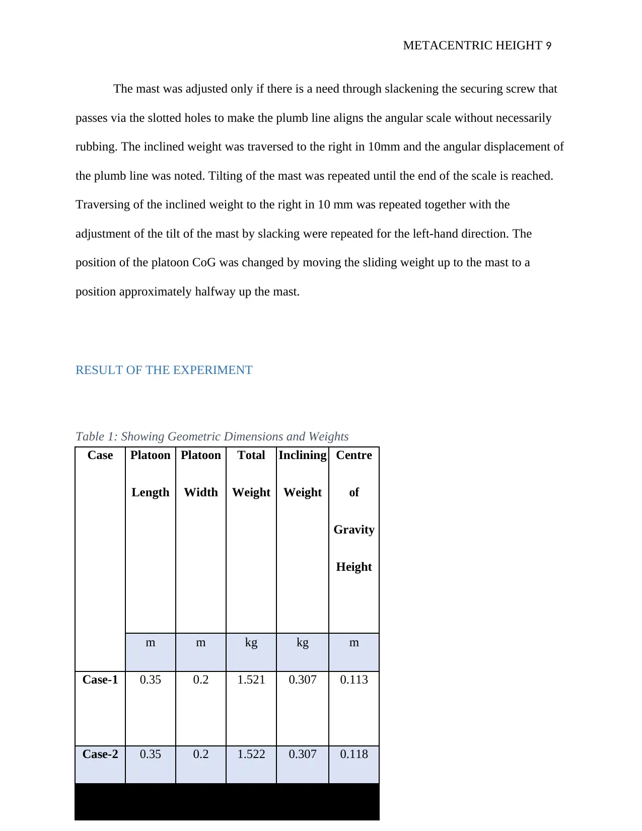
Table 1: Showing Geometric Dimensions and Weights
Case Platoon Platoon Total Inclining Centre
Length Width Weight Weight of
Gravity
Height
m m kg kg m
Case-1 0.35 0.2 1.521 0.307 0.113
Case-2 0.35 0.2 1.522 0.307 0.118
The mast was adjusted only if there is a need through slackening the securing screw that
passes via the slotted holes to make the plumb line aligns the angular scale without necessarily
rubbing. The inclined weight was traversed to the right in 10mm and the angular displacement of
the plumb line was noted. Tilting of the mast was repeated until the end of the scale is reached.
Traversing of the inclined weight to the right in 10 mm was repeated together with the
adjustment of the tilt of the mast by slacking were repeated for the left-hand direction. The
position of the platoon CoG was changed by moving the sliding weight up to the mast to a
position approximately halfway up the mast.
RESULT OF THE EXPERIMENT
Table 1: Showing Geometric Dimensions and Weights
Case Platoon Platoon Total Inclining Centre
Length Width Weight Weight of
Gravity
Height
m m kg kg m
Case-1 0.35 0.2 1.521 0.307 0.113
Case-2 0.35 0.2 1.522 0.307 0.118
⊘ This is a preview!⊘
Do you want full access?
Subscribe today to unlock all pages.
Trusted by 1+ million students worldwide
METACENTRIC HEIGHT 10
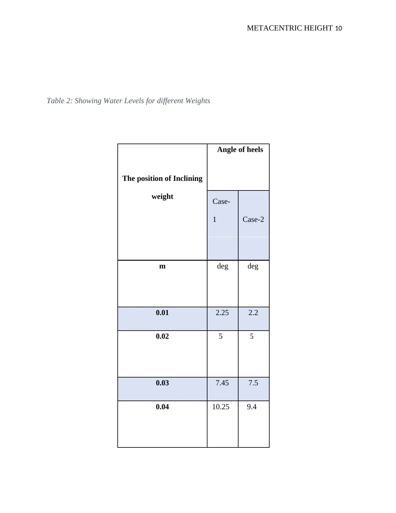
Table 2: Showing Water Levels for different Weights
Angle of heels
The position of Inclining
weight Case-
1 Case-2
m deg deg
0.01 2.25 2.2
0.02 5 5
0.03 7.45 7.5
0.04 10.25 9.4
Table 2: Showing Water Levels for different Weights
Angle of heels
The position of Inclining
weight Case-
1 Case-2
m deg deg
0.01 2.25 2.2
0.02 5 5
0.03 7.45 7.5
0.04 10.25 9.4
Paraphrase This Document
Need a fresh take? Get an instant paraphrase of this document with our AI Paraphraser
METACENTRIC HEIGHT 11
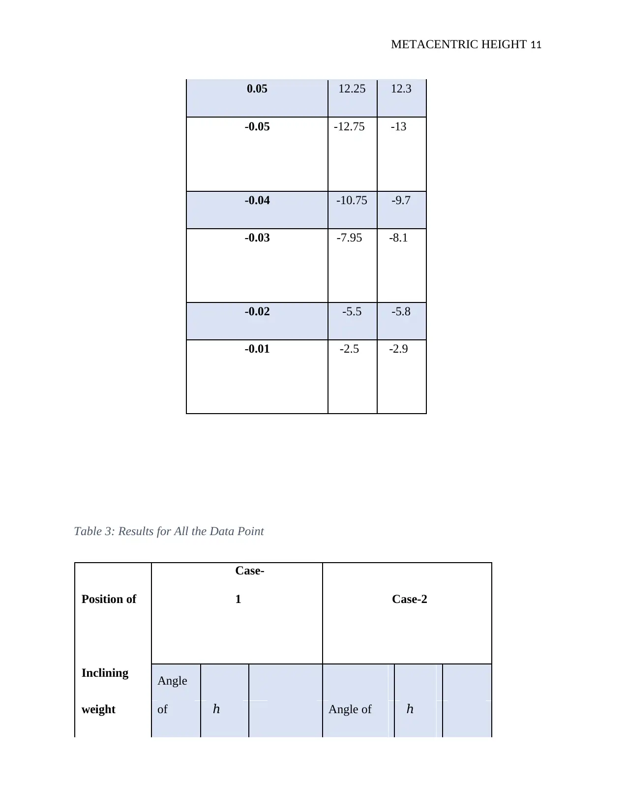
0.05 12.25 12.3
-0.05 -12.75 -13
-0.04 -10.75 -9.7
-0.03 -7.95 -8.1
-0.02 -5.5 -5.8
-0.01 -2.5 -2.9
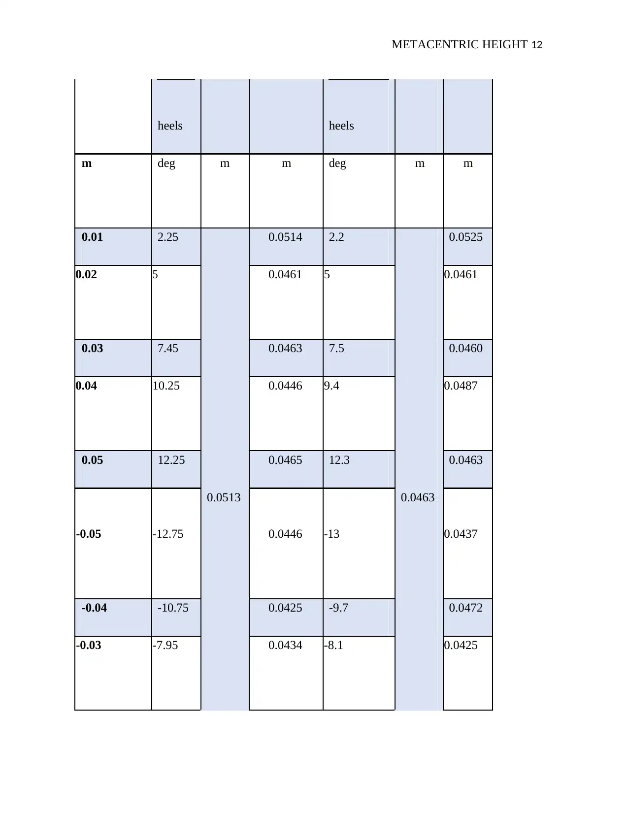
Table 3: Results for All the Data Point
Position of
Case-
1 Case-2
Inclining Angle
of ℎ Angle of ℎweight
0.05 12.25 12.3
-0.05 -12.75 -13
-0.04 -10.75 -9.7
-0.03 -7.95 -8.1
-0.02 -5.5 -5.8
-0.01 -2.5 -2.9
Table 3: Results for All the Data Point
Position of
Case-
1 Case-2
Inclining Angle
of ℎ Angle of ℎweight
METACENTRIC HEIGHT 12
heels heels
m deg m m deg m m
0.01 2.25 0.0514 2.2 0.0525
0.02 5 0.0461 5 0.0461
0.03 7.45 0.0463 7.5 0.0460
0.04 10.25 0.0446 9.4 0.0487
0.05 12.25
0.0513
0.0465 12.3
0.0463
0.0463
-0.05 -12.75 0.0446 -13 0.0437
-0.04 -10.75 0.0425 -9.7 0.0472
-0.03 -7.95 0.0434 -8.1 0.0425
heels heels
m deg m m deg m m
0.01 2.25 0.0514 2.2 0.0525
0.02 5 0.0461 5 0.0461
0.03 7.45 0.0463 7.5 0.0460
0.04 10.25 0.0446 9.4 0.0487
0.05 12.25
0.0513
0.0465 12.3
0.0463
0.0463
-0.05 -12.75 0.0446 -13 0.0437
-0.04 -10.75 0.0425 -9.7 0.0472
-0.03 -7.95 0.0434 -8.1 0.0425
⊘ This is a preview!⊘
Do you want full access?
Subscribe today to unlock all pages.
Trusted by 1+ million students worldwide
1 out of 17

Your All-in-One AI-Powered Toolkit for Academic Success.
+13062052269
info@desklib.com
Available 24*7 on WhatsApp / Email
![[object Object]](/_next/static/media/star-bottom.7253800d.svg)
Unlock your academic potential
Copyright © 2020–2025 A2Z Services. All Rights Reserved. Developed and managed by ZUCOL.