Mechanical Engineering: Handlebar Assembly Analysis Report
VerifiedAdded on 2023/04/23
|22
|3609
|262
Report
AI Summary
This mechanical engineering report investigates the impact of changing plate dimensions on the assembly of a handlebar connected to a stem, focusing on mountain bike applications. The study utilizes finite element analysis (FEA) to evaluate the effects of these dimensional changes on stress distribution and assembly life. The report details the materials used, including different stem and handlebar configurations, and quantifies assembly stress through instrumented testing. It then presents FEA simulations based on established composite plate theory, analyzing the mechanical characterization and failure modes. The results, including stress concentration and fatigue analysis, are compared with experimental data. The research aims to determine the optimal plate dimensions for enhanced handlebar durability and performance, considering factors like assembly stresses and stress fixation. The conclusion highlights how the plate dimension alterations affected the structure and robustness of the handlebar assembly, demonstrating the importance of these design choices for ensuring the structural integrity and longevity of the bike components.
MECHANICAL ENGINEERING
[Author Name(s), First M. Last, Omit Titles and Degrees]
[Institutional Affiliation(s)]
[Author Name(s), First M. Last, Omit Titles and Degrees]
[Institutional Affiliation(s)]
Paraphrase This Document
Need a fresh take? Get an instant paraphrase of this document with our AI Paraphraser
LIST OF FIGURES
Figure 1……………………………… Assembly diagram.
Figure 2……………………………… Original dimensions.
Figure 3……………………………… Illustrative failure mode.
Figure 4……………………………… Assembly diagram with changed dimensions
Figure 5……………………………… Deformation process sample
Figure 6……………………………… Displacement pattern results
LIST OF TABLES
Table 1…………………. Table 1: FEA Analysis of the thickness and length of the plate
Table 2……………… Table 2: FEA Analysis of the thickness and length of the plate
Table 3……………… Table 3: FEA Analysis of the thickness and length of the plate
Contents
LIST OF FIGURES..........................................................................................................................................2
LIST OF TABLES............................................................................................................................................2
ABSTRACT....................................................................................................................................................5
1.0 INTRODUCTION.....................................................................................................................................6
2.0 METHODS..............................................................................................................................................8
2.1 Materials............................................................................................................................................8
2.2 Quantifying Assembly........................................................................................................................8
2.3 Finite element Simulation................................................................................................................13
3.0 RESULTS...............................................................................................................................................15
3.1 Mechanical Characterization..........................................................................................................16
4.0 CONCLUSION.......................................................................................................................................17
5.0 REFERENCES........................................................................................................................................18
6.0 APPENDICES.........................................................................................................................................20
⊘ This is a preview!⊘
Do you want full access?
Subscribe today to unlock all pages.
Trusted by 1+ million students worldwide

Paraphrase This Document
Need a fresh take? Get an instant paraphrase of this document with our AI Paraphraser
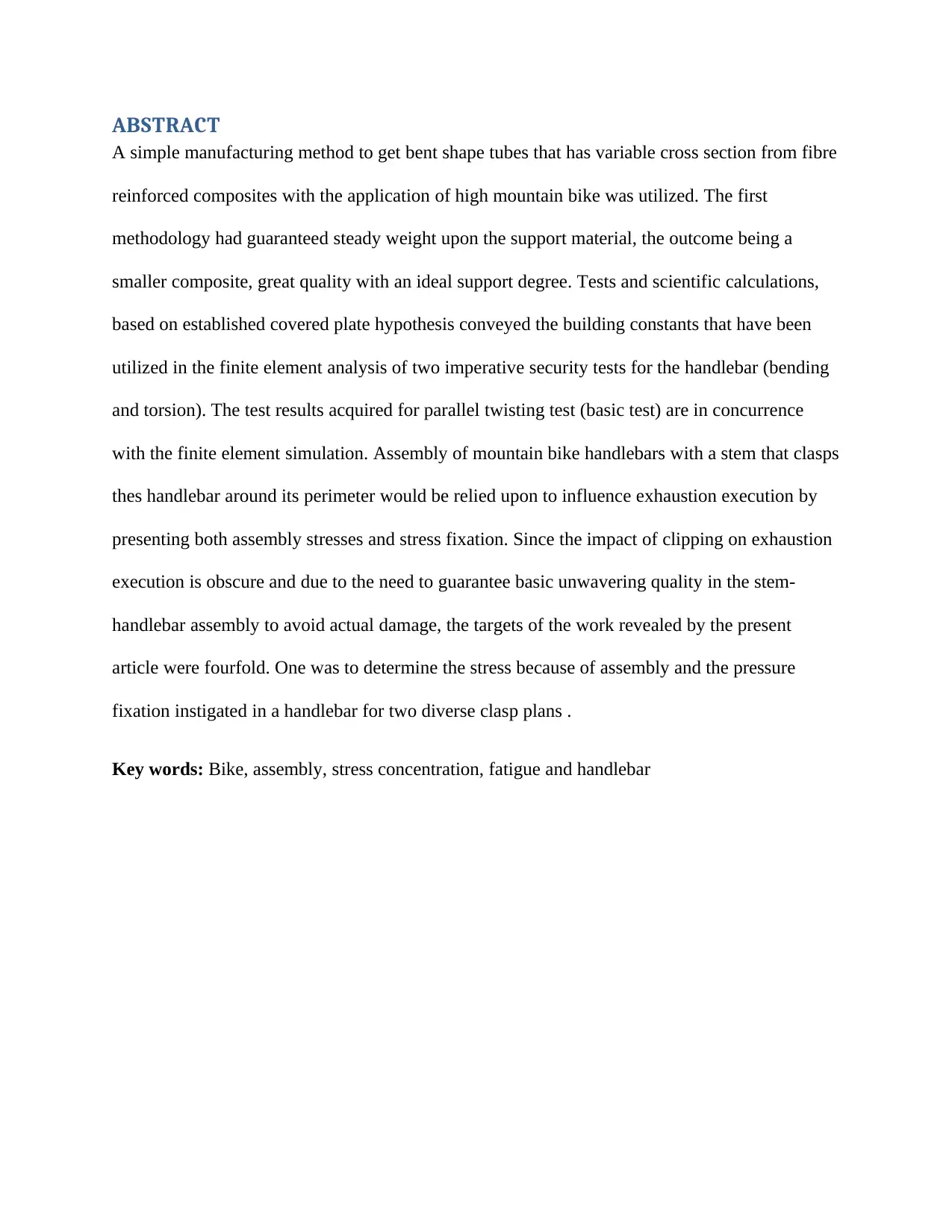
ABSTRACT
A simple manufacturing method to get bent shape tubes that has variable cross section from fibre
reinforced composites with the application of high mountain bike was utilized. The first
methodology had guaranteed steady weight upon the support material, the outcome being a
smaller composite, great quality with an ideal support degree. Tests and scientific calculations,
based on established covered plate hypothesis conveyed the building constants that have been
utilized in the finite element analysis of two imperative security tests for the handlebar (bending
and torsion). The test results acquired for parallel twisting test (basic test) are in concurrence
with the finite element simulation. Assembly of mountain bike handlebars with a stem that clasps
thes handlebar around its perimeter would be relied upon to influence exhaustion execution by
presenting both assembly stresses and stress fixation. Since the impact of clipping on exhaustion
execution is obscure and due to the need to guarantee basic unwavering quality in the stem-
handlebar assembly to avoid actual damage, the targets of the work revealed by the present
article were fourfold. One was to determine the stress because of assembly and the pressure
fixation instigated in a handlebar for two diverse clasp plans .
Key words: Bike, assembly, stress concentration, fatigue and handlebar
1.0 INTRODUCTION
When there is a failure in the parts of the bike, some of the consequences include the loss of the
ability to control the direction and also regulation of the braking. Balancing of the weight of the
rider is also not possible considering that this is the point that determines all the key concepts.
When such significant controls cannot be achieved, the consequences include practical damages
to the part. It is however regrettable that failure of such secondary parts affects the structure and
the compatibility of the components in the obtained assembly. The challenges that emerge from
the components of the assembly system is the control of the stress of forces that connects the
handle bar and the stem components itself. The required steps of ensuring that there is proper
clamping should be guided with the sudden changes in the compactness of the base section and
the stem with the handlebar (Collins, Leen & Gibson 2016).
The taking of the measurements of the impacts of the assembly are basically hard to perform.
When there is failure in dismantling of the structure, the procedure is normally logical. This has
been the case considering that the manufacturer normally rely on different components that are
from different providers. There is likelihood that the parts from different providers may not
match effectively. This brings variation. The slight dimensions variation affects the capacity of
the assembled components to withstand the pressure effects from the ground. The operation life
cycle is influenced by the information that is available on the plan of the item and its
performance as well. (Koemle & Morawetz 2016).
The main objective of the work that has been presented here was basically evaluating the impacts
of changing the dimensions of the plate in the assembly of the handle bar connected to the stem.
This was the perfect opportunity to determine the duration of the assembly life. The evaluation
process actually dwells on the configuration of the pate that clamps to the stem by the means of
⊘ This is a preview!⊘
Do you want full access?
Subscribe today to unlock all pages.
Trusted by 1+ million students worldwide
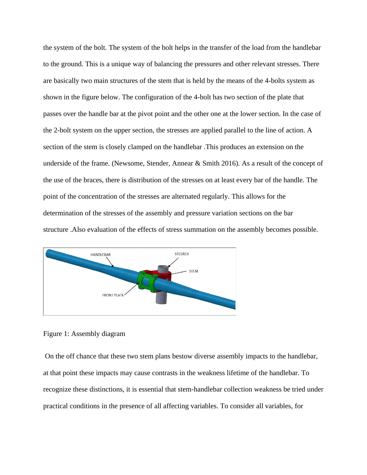
the system of the bolt. The system of the bolt helps in the transfer of the load from the handlebar
to the ground. This is a unique way of balancing the pressures and other relevant stresses. There
are basically two main structures of the stem that is held by the means of the 4-bolts system as
shown in the figure below. The configuration of the 4-bolt has two section of the plate that
passes over the handle bar at the pivot point and the other one at the lower section. In the case of
the 2-bolt system on the upper section, the stresses are applied parallel to the line of action. A
section of the stem is closely clamped on the handlebar .This produces an extension on the
underside of the frame. (Newsome, Stender, Annear & Smith 2016). As a result of the concept of
the use of the braces, there is distribution of the stresses on at least every bar of the handle. The
point of the concentration of the stresses are alternated regularly. This allows for the
determination of the stresses of the assembly and pressure variation sections on the bar
structure .Also evaluation of the effects of stress summation on the assembly becomes possible.
Figure 1: Assembly diagram
On the off chance that these two stem plans bestow diverse assembly impacts to the handlebar,
at that point these impacts may cause contrasts in the weakness lifetime of the handlebar. To
recognize these distinctions, it is essential that stem-handlebar collection weakness be tried under
practical conditions in the presence of all affecting variables. To consider all variables, for
Paraphrase This Document
Need a fresh take? Get an instant paraphrase of this document with our AI Paraphraser
example, clasp edge geometry, stress, and assembly impacts, the handlebar must be tested with
the stem joined.
2.0 METHODS
2.1 Materials
One stems and two handlebar were browsed average usually accessible parts for rough terrain
bikes. One stem was a 4-bolts stem, where the clamshell-style handlebar cinch shot together on
the underside of the stem .The 4-bolts stem was made of steel and had no riser edge, implying
that the stem expansion was opposite to the plume. The other stem was a 4-bolt stem, which had
a front plate that utilized two bolts to brace the handlebar set up. The 4-jolt stem was made of
aluminum and had a 10° ascent point. The 4-bolts stem estimated 35 mm over the clip and the 2-
jolt stem estimated 50 mm over the clasp(Dwyer, Shaw & Tombarelli 2012). The edge of the
clips at the clasp handlebar intersection varied in that the edge of the 4-bolt stem was a corner,
while the edge of the 2-jolt stem was adjusted (span around 1 mm). The handlebar was 580 mm
long and had an ostensible outside breadth of 25.4 mm and an inside breadth of 21.0 mm.
2.2 Quantifying Assembly
An instrumented handlebar and a bolt constrain transducer were developed to determine the
assembly stress around the external surface of the handlebar. To gauge strains in the handlebar,
four opposite strain gage rosettes were mounted on a perimeter on the external surface of the
handlebar at 90° interims so the gages were situated in the longitudinal and transverse bearings
of the handlebar. The longitudinal heading was along the length of the handlebar. To guarantee
consistency in the clipping power when fixing the stem cinch bolt(s), the bolt constrain (i.e.,
strain) was estimated(Sperlich, Achtzehn, Buhr, Zinner, Zelle & Holmberg 2012).
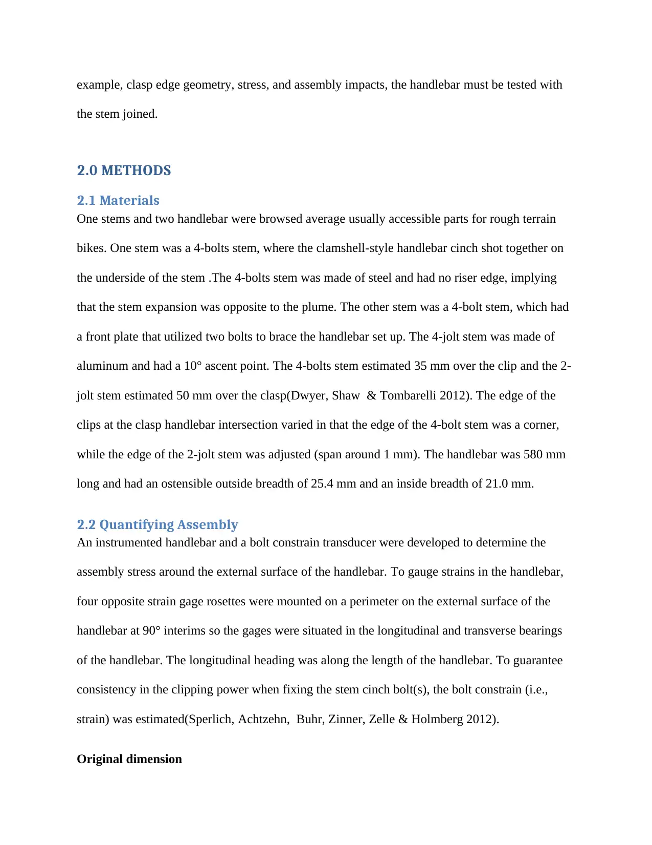
Original dimension
the stem joined.
2.0 METHODS
2.1 Materials
One stems and two handlebar were browsed average usually accessible parts for rough terrain
bikes. One stem was a 4-bolts stem, where the clamshell-style handlebar cinch shot together on
the underside of the stem .The 4-bolts stem was made of steel and had no riser edge, implying
that the stem expansion was opposite to the plume. The other stem was a 4-bolt stem, which had
a front plate that utilized two bolts to brace the handlebar set up. The 4-jolt stem was made of
aluminum and had a 10° ascent point. The 4-bolts stem estimated 35 mm over the clip and the 2-
jolt stem estimated 50 mm over the clasp(Dwyer, Shaw & Tombarelli 2012). The edge of the
clips at the clasp handlebar intersection varied in that the edge of the 4-bolt stem was a corner,
while the edge of the 2-jolt stem was adjusted (span around 1 mm). The handlebar was 580 mm
long and had an ostensible outside breadth of 25.4 mm and an inside breadth of 21.0 mm.
2.2 Quantifying Assembly
An instrumented handlebar and a bolt constrain transducer were developed to determine the
assembly stress around the external surface of the handlebar. To gauge strains in the handlebar,
four opposite strain gage rosettes were mounted on a perimeter on the external surface of the
handlebar at 90° interims so the gages were situated in the longitudinal and transverse bearings
of the handlebar. The longitudinal heading was along the length of the handlebar. To guarantee
consistency in the clipping power when fixing the stem cinch bolt(s), the bolt constrain (i.e.,
strain) was estimated(Sperlich, Achtzehn, Buhr, Zinner, Zelle & Holmberg 2012).
Original dimension
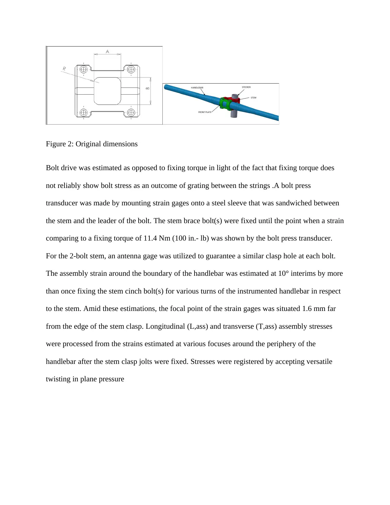
Figure 2: Original dimensions
Bolt drive was estimated as opposed to fixing torque in light of the fact that fixing torque does
not reliably show bolt stress as an outcome of grating between the strings .A bolt press
transducer was made by mounting strain gages onto a steel sleeve that was sandwiched between
the stem and the leader of the bolt. The stem brace bolt(s) were fixed until the point when a strain
comparing to a fixing torque of 11.4 Nm (100 in.- lb) was shown by the bolt press transducer.
For the 2-bolt stem, an antenna gage was utilized to guarantee a similar clasp hole at each bolt.
The assembly strain around the boundary of the handlebar was estimated at 10° interims by more
than once fixing the stem cinch bolt(s) for various turns of the instrumented handlebar in respect
to the stem. Amid these estimations, the focal point of the strain gages was situated 1.6 mm far
from the edge of the stem clasp. Longitudinal (L,ass) and transverse (T,ass) assembly stresses
were processed from the strains estimated at various focuses around the periphery of the
handlebar after the stem clasp jolts were fixed. Stresses were registered by accepting versatile
twisting in plane pressure
⊘ This is a preview!⊘
Do you want full access?
Subscribe today to unlock all pages.
Trusted by 1+ million students worldwide
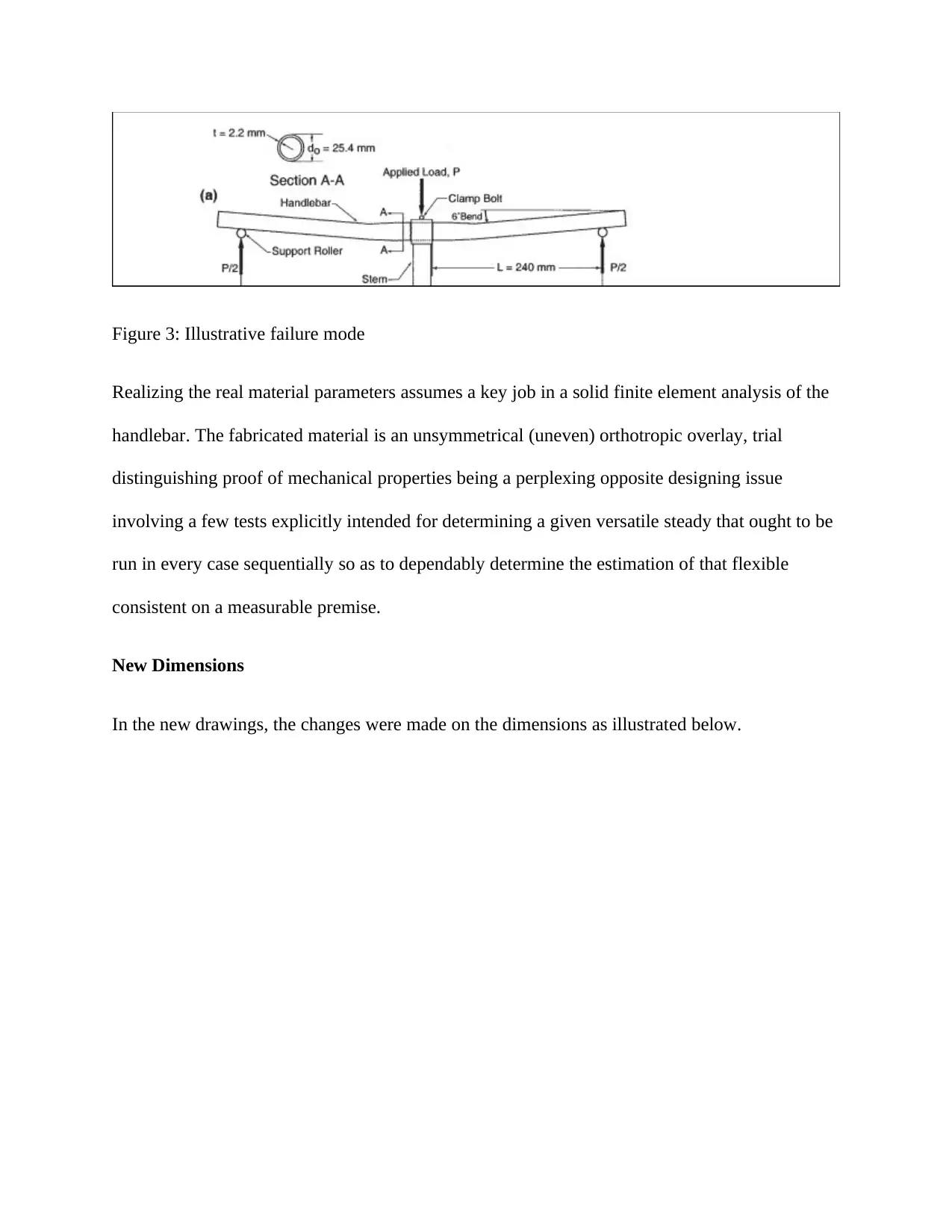
Figure 3: Illustrative failure mode
Realizing the real material parameters assumes a key job in a solid finite element analysis of the
handlebar. The fabricated material is an unsymmetrical (uneven) orthotropic overlay, trial
distinguishing proof of mechanical properties being a perplexing opposite designing issue
involving a few tests explicitly intended for determining a given versatile steady that ought to be
run in every case sequentially so as to dependably determine the estimation of that flexible
consistent on a measurable premise.
New Dimensions
In the new drawings, the changes were made on the dimensions as illustrated below.
Paraphrase This Document
Need a fresh take? Get an instant paraphrase of this document with our AI Paraphraser
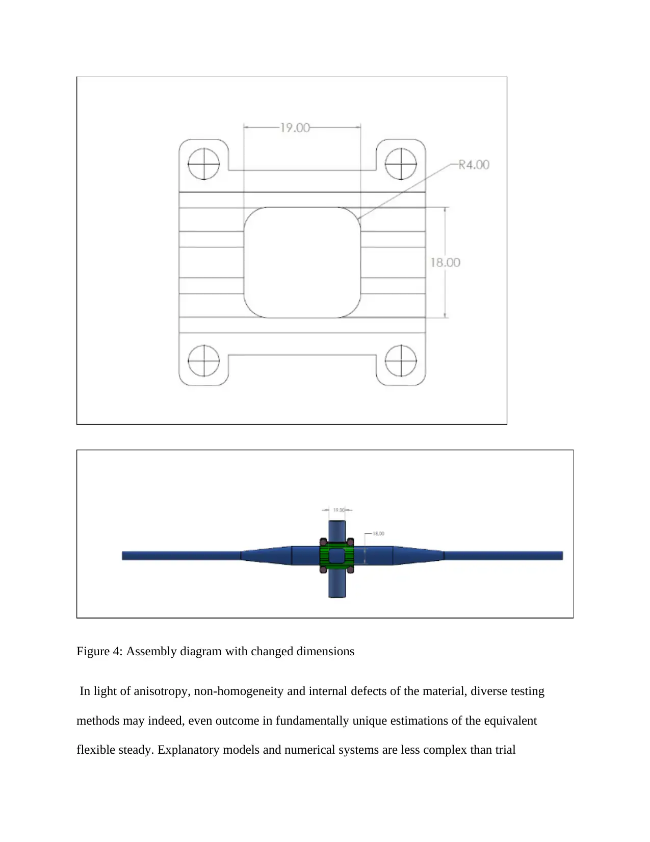
Figure 4: Assembly diagram with changed dimensions
In light of anisotropy, non-homogeneity and internal defects of the material, diverse testing
methods may indeed, even outcome in fundamentally unique estimations of the equivalent
flexible steady. Explanatory models and numerical systems are less complex than trial
In light of anisotropy, non-homogeneity and internal defects of the material, diverse testing
methods may indeed, even outcome in fundamentally unique estimations of the equivalent
flexible steady. Explanatory models and numerical systems are less complex than trial
systems .However; they are regularly founded on exceedingly admired conditions that might be
straightforwardly interestingly with the real conduct of the material. In the FE simulation the
composite cover has been viewed as a solitary layer proportionate model with orthotropic
conduct portrayed by a lot of nine designing constants. Figuring of the material constants was
done utilizing a hypothetically dependent on traditional overlaid plate hypothesis programming,
for performing linear counts, called The Laminator ver(Lopes & McCormack 2017).
Impacts/effects of the dimension change
The change of the dimensions of the plate made the structure more robust as compared to the
original structure. This was evident from the high magnitude of the values of the stresses.
In light of single utility material properties and layup (stacking succession), the product
figures ,the obvious overlay firmness properties, Poisson and shear coupling coefficients and
must be considered alongside solidness lattices of the overlay. Table below demonstrates the
immediate information which is the material properties of individual handles as per the designer.
Bi-directional handle was considered for figuring as two unit-directional layers having the half of
thickness and introduction +45° and - 45° individually.
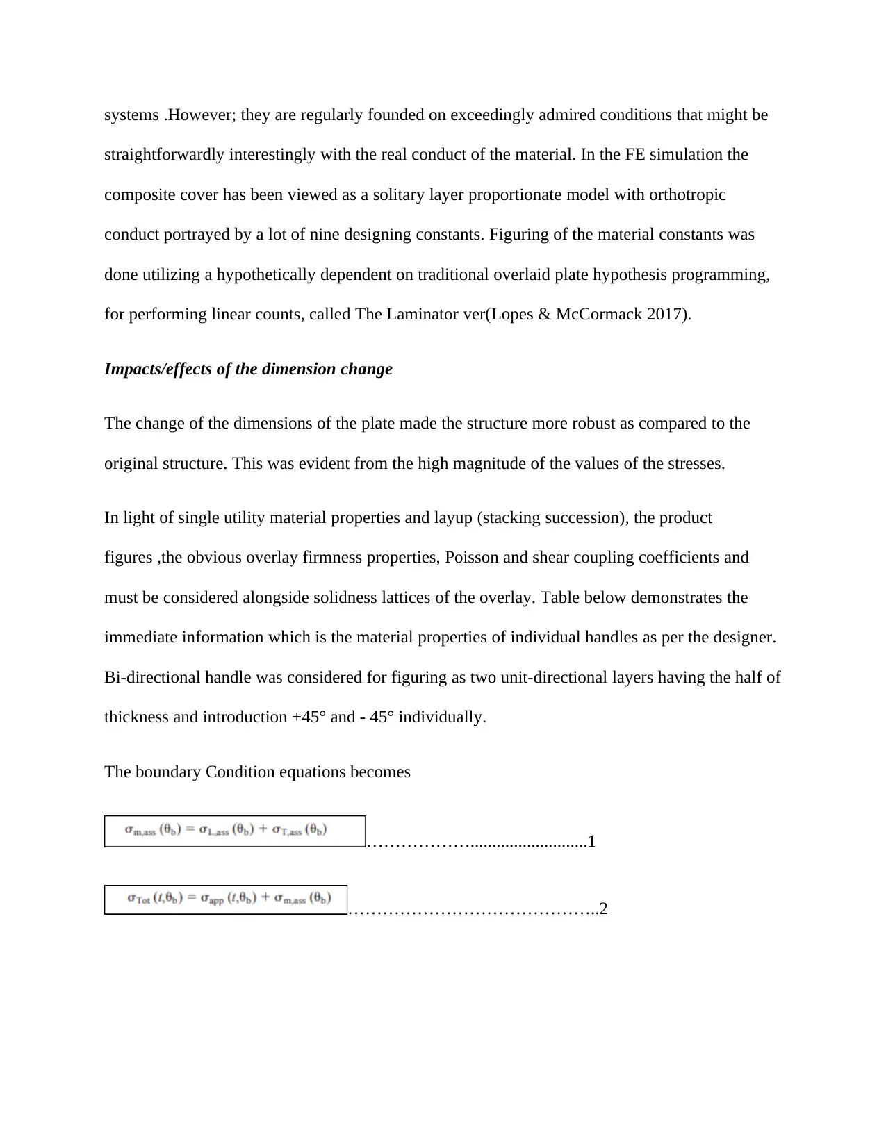
The boundary Condition equations becomes
………………...........................1
……………………………………..2
straightforwardly interestingly with the real conduct of the material. In the FE simulation the
composite cover has been viewed as a solitary layer proportionate model with orthotropic
conduct portrayed by a lot of nine designing constants. Figuring of the material constants was
done utilizing a hypothetically dependent on traditional overlaid plate hypothesis programming,
for performing linear counts, called The Laminator ver(Lopes & McCormack 2017).
Impacts/effects of the dimension change
The change of the dimensions of the plate made the structure more robust as compared to the
original structure. This was evident from the high magnitude of the values of the stresses.
In light of single utility material properties and layup (stacking succession), the product
figures ,the obvious overlay firmness properties, Poisson and shear coupling coefficients and
must be considered alongside solidness lattices of the overlay. Table below demonstrates the
immediate information which is the material properties of individual handles as per the designer.
Bi-directional handle was considered for figuring as two unit-directional layers having the half of
thickness and introduction +45° and - 45° individually.
The boundary Condition equations becomes
………………...........................1
……………………………………..2
⊘ This is a preview!⊘
Do you want full access?
Subscribe today to unlock all pages.
Trusted by 1+ million students worldwide
1 out of 22

Your All-in-One AI-Powered Toolkit for Academic Success.
+13062052269
info@desklib.com
Available 24*7 on WhatsApp / Email
![[object Object]](/_next/static/media/star-bottom.7253800d.svg)
Unlock your academic potential
Copyright © 2020–2026 A2Z Services. All Rights Reserved. Developed and managed by ZUCOL.