Mechanical Principles Assignment: Torque, Joints, Flywheels
VerifiedAdded on 2022/10/10
|10
|690
|483
Homework Assignment
AI Summary
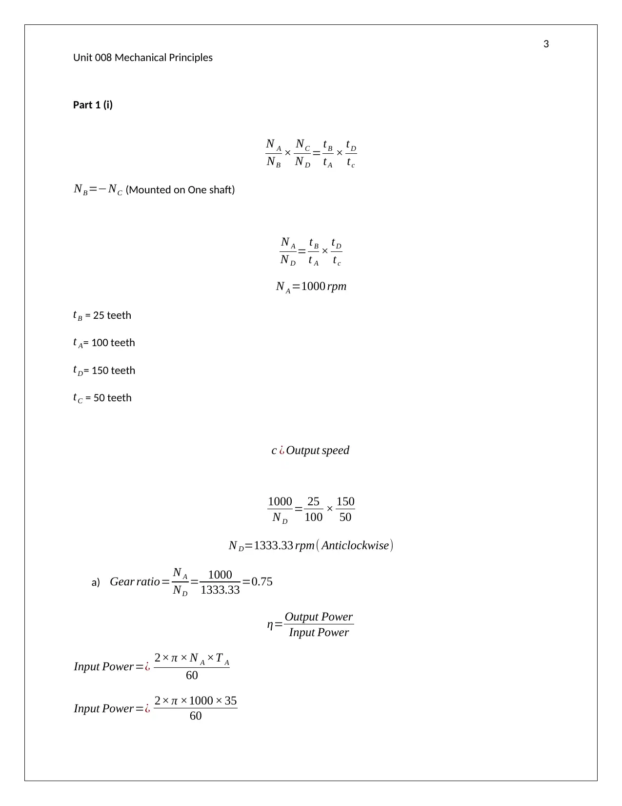
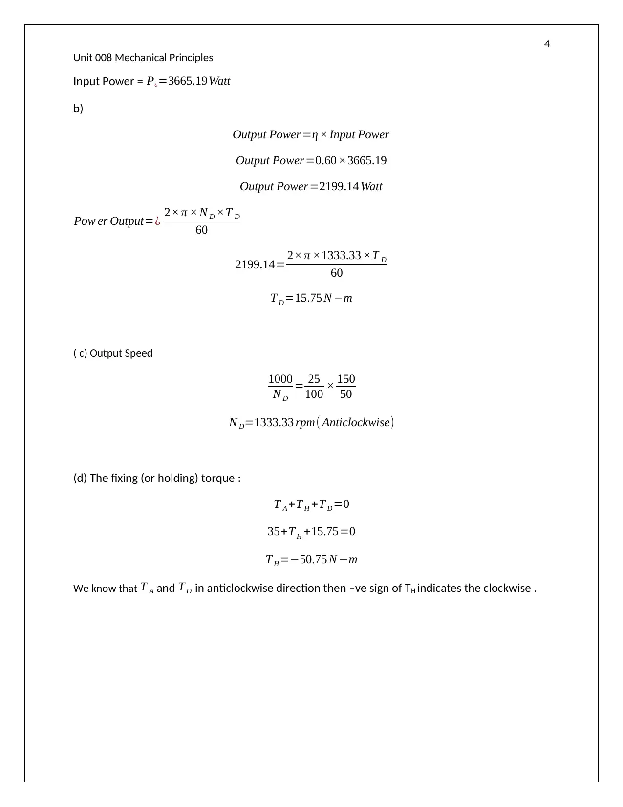
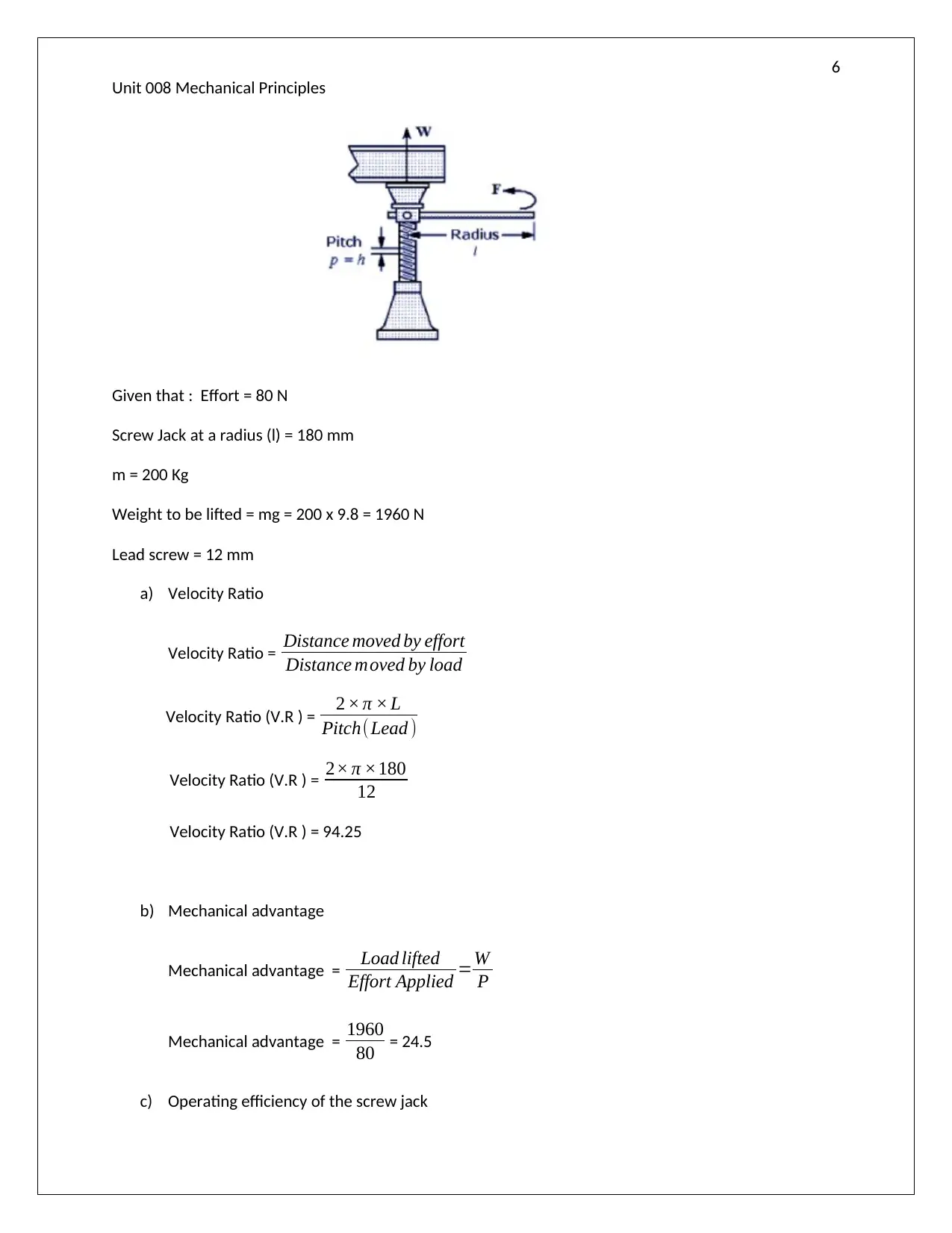
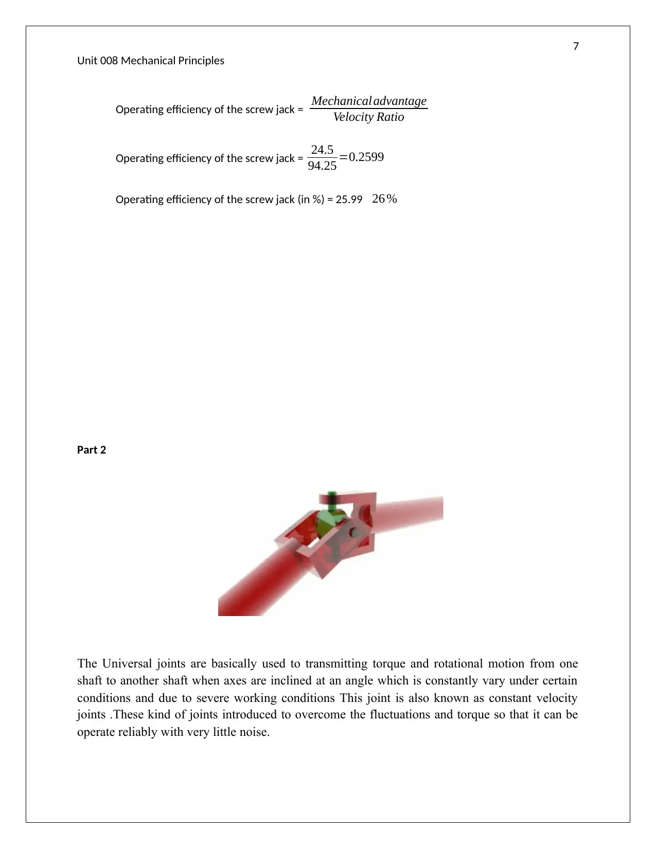
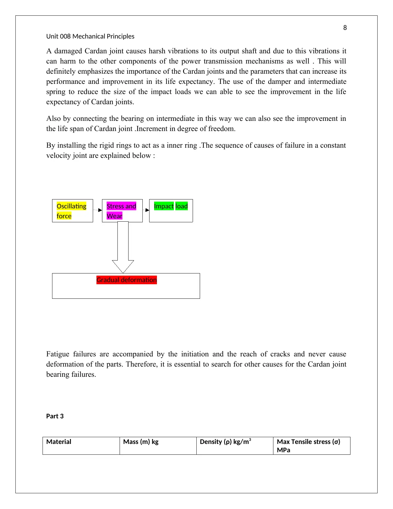
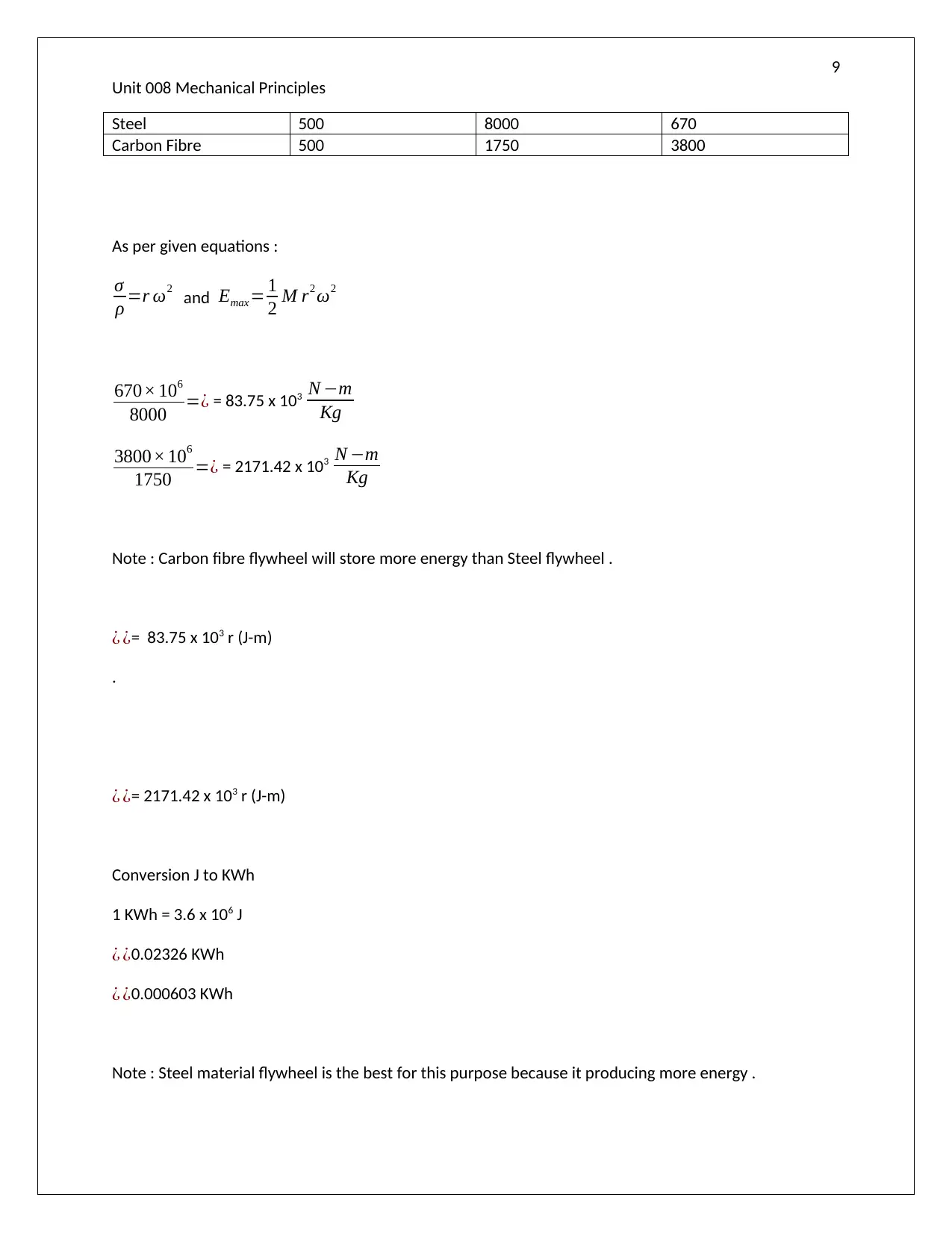
This assignment solution covers key concepts in mechanical principles, including torque calculations, analysis of universal joints, and flywheel design. Part 1 addresses gear ratios, torque, and screw jack calculations, determining mechanical advantage and efficiency. Part 2 focuses on universal joints, their function, and causes of failure, emphasizing the importance of joint design and maintenance. Part 3 compares the energy storage capabilities of steel and carbon fiber flywheels, analyzing material properties and energy storage capacity. The solution provides detailed calculations, explanations, and references to support the analysis, making it a comprehensive resource for understanding mechanical engineering principles.

Mechanical Principles
Paraphrase This Document
Need a fresh take? Get an instant paraphrase of this document with our AI Paraphraser

2
Unit 008 Mechanical Principles
Table of Contents
Part 1..........................................................................................................................................................3
Part 2.......................................................................................................................................................3
Part 3.......................................................................................................................................................3
References List ........................................................................................................................................3

3
Unit 008 Mechanical Principles
Part 1 (i)
N A
NB
× NC
N D
= tB
tA
× t D
tc
NB =−NC (Mounted on One shaft)
N A
N D
= t B
t A
× tD
tc
N A =1000 rpm
tB = 25 teeth
t A= 100 teeth
tD= 150 teeth
tC = 50 teeth
c ¿ Output speed
1000
N D
= 25
100 × 150
50
N D=1333.33 rpm( Anticlockwise)
a) Gear ratio= N A
ND
= 1000
1333.33 =0.75
η=Output Power
Input Power
Input Power=¿ 2× π × N A ×T A
60
Input Power=¿ 2× π ×1000 × 35
60
⊘ This is a preview!⊘
Do you want full access?
Subscribe today to unlock all pages.

Trusted by 1+ million students worldwide

4
Unit 008 Mechanical Principles
Input Power = P¿=3665.19Watt
b)
Output Power=η × Input Power
Output Power=0.60 ×3665.19
Output Power=2199.14 Watt
Pow er Output=¿ 2× π × N D ×T D
60
2199.14= 2× π ×1333.33 ×T D
60
T D =15.75 N −m
( c) Output Speed
1000
N D
= 25
100 × 150
50
N D=1333.33 rpm( Anticlockwise)
(d) The fixing (or holding) torque :
T A +T H +T D =0
35+T H +15.75=0
T H =−50.75 N −m
We know that T A and T D in anticlockwise direction then –ve sign of TH indicates the clockwise .
Paraphrase This Document
Need a fresh take? Get an instant paraphrase of this document with our AI Paraphraser

5
Unit 008 Mechanical Principles
(ii)
Given that :
Maximum Load (Fa) = 16 KN
Torque (T) = 20 N-m
Pitch width (l) = 5 mm
Efficiency ( η ) = Fa l
2 πT = 16 ×103 ×5 ×10−3
2× π × 20
Efficiency ( η ) =.6366
Efficiency ( η )=63.66 %
(iii)
Unit 008 Mechanical Principles
(ii)
Given that :
Maximum Load (Fa) = 16 KN
Torque (T) = 20 N-m
Pitch width (l) = 5 mm
Efficiency ( η ) = Fa l
2 πT = 16 ×103 ×5 ×10−3
2× π × 20
Efficiency ( η ) =.6366
Efficiency ( η )=63.66 %
(iii)

6
Unit 008 Mechanical Principles
Given that : Effort = 80 N
Screw Jack at a radius (l) = 180 mm
m = 200 Kg
Weight to be lifted = mg = 200 x 9.8 = 1960 N
Lead screw = 12 mm
a) Velocity Ratio
Velocity Ratio = Distance moved by effort
Distance moved by load
Velocity Ratio (V.R ) = 2 × π × L
Pitch( Lead )
Velocity Ratio (V.R ) = 2× π ×180
12
Velocity Ratio (V.R ) = 94.25
b) Mechanical advantage
Mechanical advantage = Load lifted
Effort Applied =W
P
Mechanical advantage = 1960
80 = 24.5
c) Operating efficiency of the screw jack
⊘ This is a preview!⊘
Do you want full access?
Subscribe today to unlock all pages.

Trusted by 1+ million students worldwide

7
Unit 008 Mechanical Principles
Operating efficiency of the screw jack = Mechanicaladvantage
Velocity Ratio
Operating efficiency of the screw jack = 24.5
94.25 =0.2599
Operating efficiency of the screw jack (in %) = 25.99 26 %
Part 2
The Universal joints are basically used to transmitting torque and rotational motion from one
shaft to another shaft when axes are inclined at an angle which is constantly vary under certain
conditions and due to severe working conditions This joint is also known as constant velocity
joints .These kind of joints introduced to overcome the fluctuations and torque so that it can be
operate reliably with very little noise.
Paraphrase This Document
Need a fresh take? Get an instant paraphrase of this document with our AI Paraphraser

8
Unit 008 Mechanical Principles
A damaged Cardan joint causes harsh vibrations to its output shaft and due to this vibrations it
can harm to the other components of the power transmission mechanisms as well . This will
definitely emphasizes the importance of the Cardan joints and the parameters that can increase its
performance and improvement in its life expectancy. The use of the damper and intermediate
spring to reduce the size of the impact loads we can able to see the improvement in the life
expectancy of Cardan joints.
Also by connecting the bearing on intermediate in this way we can also see the improvement in
the life span of Cardan joint .Increment in degree of freedom.
By installing the rigid rings to act as a inner ring .The sequence of causes of failure in a constant
velocity joint are explained below :
Fatigue failures are accompanied by the initiation and the reach of cracks and never cause
deformation of the parts. Therefore, it is essential to search for other causes for the Cardan joint
bearing failures.
Part 3
Material Mass (m) kg Density (ρ) kg/m3 Max Tensile stress (σ)
MPa
Oscillating
force
Stress and
Wear
Impact load
Gradual deformation

9
Unit 008 Mechanical Principles
Steel 500 8000 670
Carbon Fibre 500 1750 3800
As per given equations :
σ
ρ =r ω2 and Emax = 1
2 M r2 ω2
670× 106
8000 =¿ = 83.75 x 10³ N −m
Kg
3800× 106
1750 =¿ = 2171.42 x 103 N −m
Kg
Note : Carbon fibre flywheel will store more energy than Steel flywheel .
¿ ¿= 83.75 x 10³ r (J-m)
.
¿ ¿= 2171.42 x 103 r (J-m)
Conversion J to KWh
1 KWh = 3.6 x 10⁶ J
¿ ¿0.02326 KWh
¿ ¿0.000603 KWh
Note : Steel material flywheel is the best for this purpose because it producing more energy .
⊘ This is a preview!⊘
Do you want full access?
Subscribe today to unlock all pages.

Trusted by 1+ million students worldwide

10
Unit 008 Mechanical Principles
1 out of 10

Your All-in-One AI-Powered Toolkit for Academic Success.
+13062052269
info@desklib.com
Available 24*7 on WhatsApp / Email
Unlock your academic potential
Copyright © 2020–2025 A2Z Services. All Rights Reserved. Developed and managed by ZUCOL.