University Project: Plan of Pump Renovation Project Design
VerifiedAdded on 2022/08/20
|12
|1935
|13
Project
AI Summary
This project presents a comprehensive plan for the renovation of a water pump system, focusing on the design and implementation of a centrifugal pumping system. The project begins with detailed design specifications, including the replacement of the existing sewage pumping system with new variable frequency drives, ensuring continuous operation throughout construction. The plan incorporates a thorough geotechnical investigation, the installation of a power box for efficient power distribution, and the selection of a centrifugal pumping system for its efficiency and low maintenance. The project includes an analysis of stakeholder influences, a detailed project schedule with a Gantt chart, a project network diagram, and a critical path analysis to ensure timely completion. The estimated budget is £55,000, and the project is scheduled to be completed within 6 months, with key milestones including the submission of the Statement of Work (SOW), centrifugal pumping system installation, completion of the project development stage, and handover of the final project plan. The project also includes a detailed breakdown of tasks, durations, resources, and costs, along with a bibliography of relevant research papers.

Running head: PLAN OF PUMP RENOVATION PROJECT DESIGN
Plan of Pump Renovation Project Design
Name of the Student:
Name of the University:
Plan of Pump Renovation Project Design
Name of the Student:
Name of the University:
Paraphrase This Document
Need a fresh take? Get an instant paraphrase of this document with our AI Paraphraser
1PLAN OF PUMP RENOVATION PROJECT DESIGN
1. Design specification from the given brief
In order to renovate the pumping station at first basic engineering services should be
selected. Existing sewage pumping system has to be replaced first. New variable frequency
drives are used to control the sewage pumping. The pumping station must remain in full
operation stage throughout the construction stage. Experienced engineers should be appointed to
develop the design. A new interior pumping will be installed along with valves and
appurtenances. Detail geotechnical investigation is needed to be conducted.
Power box installation is required to control power consumption rate. It will distribute the
voltage across the entire equipment setup. It isolates the appliance setup to improve reliability. It
also allows the users to manually distribute power supply. It distributes the loss among all the
circuit parts. The centrifugal pumping system is used in this system to get higher efficiency and
lower down the power consumptions. It lowers down the noise level and NPHS requirements as
well. The maintenance cost of the centrifugal pump is very low. The different components used
in the centrifugal pump are impeller, back plate, mechanical seal, pump shaft, connectors,
adopter, shroud, legs and pump casing.
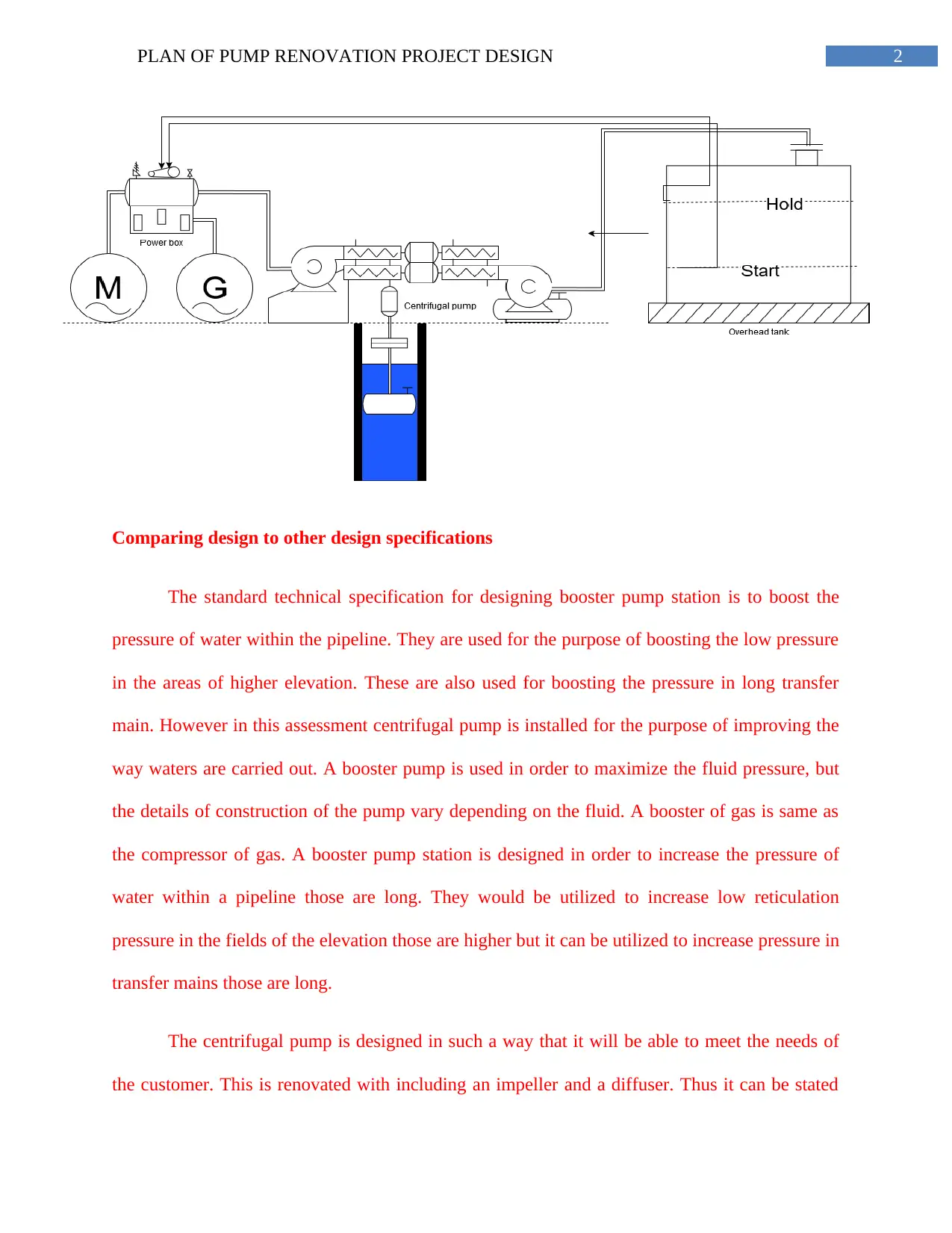
In the process of engineering analysis a centrifugal pump is also installed to hold and
start the overhead tank. The existing electrical system is also needed to upgrade for facilitating
sewage pumps and replace the power distribution operations. The power box and overhead tank
is connected through centrifugal pumping system. If this design is successfully executed and
specified then pump capacity will improve and upgraded according to the early expectation. The
system is comprises of centrifugal pumping, overhead tank to store water and a control
mechanism with vault.
1. Design specification from the given brief
In order to renovate the pumping station at first basic engineering services should be
selected. Existing sewage pumping system has to be replaced first. New variable frequency
drives are used to control the sewage pumping. The pumping station must remain in full
operation stage throughout the construction stage. Experienced engineers should be appointed to
develop the design. A new interior pumping will be installed along with valves and
appurtenances. Detail geotechnical investigation is needed to be conducted.
Power box installation is required to control power consumption rate. It will distribute the
voltage across the entire equipment setup. It isolates the appliance setup to improve reliability. It
also allows the users to manually distribute power supply. It distributes the loss among all the
circuit parts. The centrifugal pumping system is used in this system to get higher efficiency and
lower down the power consumptions. It lowers down the noise level and NPHS requirements as
well. The maintenance cost of the centrifugal pump is very low. The different components used
in the centrifugal pump are impeller, back plate, mechanical seal, pump shaft, connectors,
adopter, shroud, legs and pump casing.
In the process of engineering analysis a centrifugal pump is also installed to hold and
start the overhead tank. The existing electrical system is also needed to upgrade for facilitating
sewage pumps and replace the power distribution operations. The power box and overhead tank
is connected through centrifugal pumping system. If this design is successfully executed and
specified then pump capacity will improve and upgraded according to the early expectation. The
system is comprises of centrifugal pumping, overhead tank to store water and a control
mechanism with vault.
2PLAN OF PUMP RENOVATION PROJECT DESIGN
Comparing design to other design specifications
The standard technical specification for designing booster pump station is to boost the
pressure of water within the pipeline. They are used for the purpose of boosting the low pressure
in the areas of higher elevation. These are also used for boosting the pressure in long transfer
main. However in this assessment centrifugal pump is installed for the purpose of improving the
way waters are carried out. A booster pump is used in order to maximize the fluid pressure, but
the details of construction of the pump vary depending on the fluid. A booster of gas is same as
the compressor of gas. A booster pump station is designed in order to increase the pressure of
water within a pipeline those are long. They would be utilized to increase low reticulation
pressure in the fields of the elevation those are higher but it can be utilized to increase pressure in
transfer mains those are long.
The centrifugal pump is designed in such a way that it will be able to meet the needs of
the customer. This is renovated with including an impeller and a diffuser. Thus it can be stated
⊘ This is a preview!⊘
Do you want full access?
Subscribe today to unlock all pages.
Trusted by 1+ million students worldwide
3PLAN OF PUMP RENOVATION PROJECT DESIGN
that use of centrifugal pump will enhance the performance. A centrifugal pump is a mechanical
device that is designed in order to move a fluid in a way by the transfer of the rotational energy
from multiple rotors those are driven that are called impellers. The fluid enters the impeller that
is rotating rapidly along the axis and it is then cast out by the centrifugal force that is along the
circumference via the vane tips of the impeller.
2. Influence of stakeholder’s design brief and requirements in preparing the
design
In order to govern any project towards expected objectives and goals it is essential to
analyze and identify influences of stakeholders in developing the design brief. For this particular
pumping system renovation project construction contractor, local builders, technicians,
plumbers, private enterprises, mechanical engineer and hydraulic engineer play influences a lot.
The mechanical engineer designs will design associate power producing machines in
terms of electric generators, internal combustions, power using machines, steam gas turbines for
the renovation of the pumping system. The hydraulic engineer will deal with the fluid flow to
control water supply rate in the nominated location. Not only this but also the hydraulic engineer
deals with the issues related to storage, water collection, transportation, regulation and control.
Interest, power and role play by each of the stakeholders mentioned influences the success of the
pumping station renovation project. In order to make sure that there is no such obstacles present
in the system, the mechanical engineer must play their assigned responbilities.
Paraphrase This Document
Need a fresh take? Get an instant paraphrase of this document with our AI Paraphraser
4PLAN OF PUMP RENOVATION PROJECT DESIGN
2. Design a project schedule with graphical illustration
2.1 Project Scope
The scope of the project is to renovate the existing water pump system with pumping as
well as ump controlling mechanism. The project will start by 29/10/2020 and will be finished by
06/10/2020. The critical path of the project is indicated with a red colour in the below diagram.
The major milestones of the project are- Milestone 1: Submitting the Statement of Work (SOW),
Milestone 2: Centrifugal pumping system installation completion, Milestone 3: Completion of
project development stage and Milestone 4: Handover of the final project plan. The total budget
estimated for the project is £55,000.
2.2 Gantt chart of the project
These days limited availability of water has become major issue in the small town areas.
Infact, rural water supplies have traditionally been overshadowed by the urban ones. In the year
of 1963 the WSSDC has installed a water tank at a nearby hill. This report depicts a detail plan
that has to be followed to renovate the water tank.
The development responsibility is taken by Water Supply and Sanitation Department
Committee (WSSDC). The former committee chairman has requested for this project. Due to
limited water supply the rural people were facing major issues with drinking water. The new
system design is comprises of centrifugal pump, overhead tank and control mechanism. In order
to renovate the water tank a Gantt chart (including start date and finish date), critical path detail,
project budget and major project milestones are elaborated in this report.
5PLAN OF PUMP RENOVATION PROJECT DESIGN
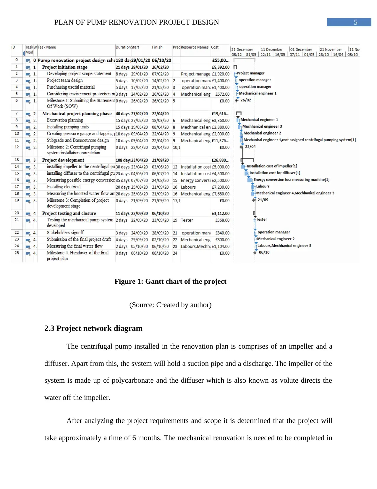
Figure 1: Gantt chart of the project
(Source: Created by author)
2.3 Project network diagram
The centrifugal pump installed in the renovation plan is comprises of an impeller and a
diffuser. Apart from this, the system will hold a suction pipe and a discharge. The impeller of the
system is made up of polycarbonate and the diffuser which is also known as volute directs the
water off the impeller.
After analyzing the project requirements and scope it is determined that the project will
take approximately a time of 6 months. The mechanical renovation is needed to be completed in
⊘ This is a preview!⊘
Do you want full access?
Subscribe today to unlock all pages.
Trusted by 1+ million students worldwide

6PLAN OF PUMP RENOVATION PROJECT DESIGN
an estimated budget rate of £55,000. Before final execution of the centrifugal pumping system
the different performance curve the will be measured include head, efficiency, power, flow rate
etc.
an estimated budget rate of £55,000. Before final execution of the centrifugal pumping system
the different performance curve the will be measured include head, efficiency, power, flow rate
etc.
Paraphrase This Document
Need a fresh take? Get an instant paraphrase of this document with our AI Paraphraser
4PLAN OF PUMP RENOVATION PROJECT DESIGN
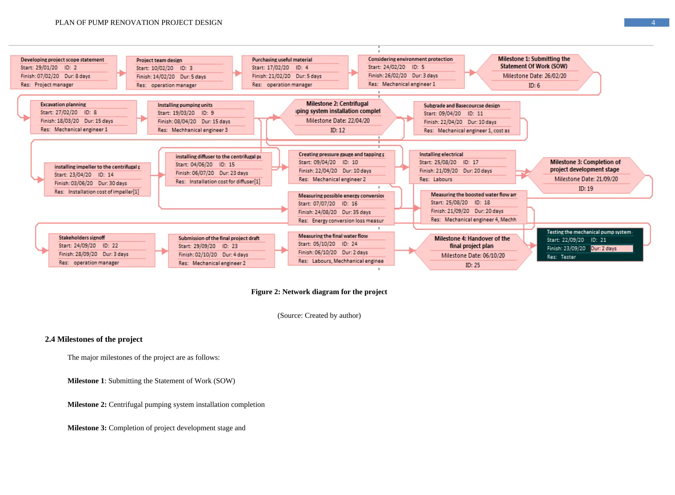
Figure 2: Network diagram for the project
(Source: Created by author)
2.4 Milestones of the project
The major milestones of the project are as follows:
Milestone 1: Submitting the Statement of Work (SOW)
Milestone 2: Centrifugal pumping system installation completion
Milestone 3: Completion of project development stage and
5PLAN OF PUMP RENOVATION PROJECT DESIGN
Milestone 4: Handover of the final project plan
2.5 Critical path analysis
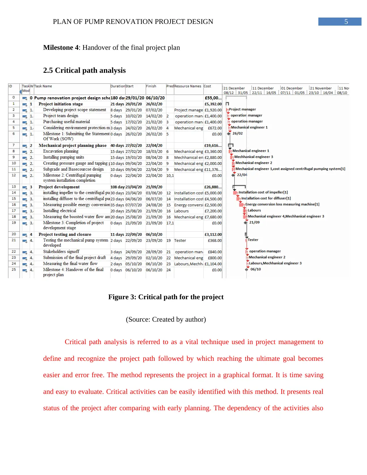
Figure 3: Critical path for the project
(Source: Created by author)
Critical path analysis is referred to as a vital technique used in project management to
define and recognize the project path followed by which reaching the ultimate goal becomes
easier and error free. The method represents the project in a graphical format. It is time saving
and easy to evaluate. Critical activities can be easily identified with this method. It presents real
status of the project after comparing with early planning. The dependency of the activities also
Milestone 4: Handover of the final project plan
2.5 Critical path analysis
Figure 3: Critical path for the project
(Source: Created by author)
Critical path analysis is referred to as a vital technique used in project management to
define and recognize the project path followed by which reaching the ultimate goal becomes
easier and error free. The method represents the project in a graphical format. It is time saving
and easy to evaluate. Critical activities can be easily identified with this method. It presents real
status of the project after comparing with early planning. The dependency of the activities also
⊘ This is a preview!⊘
Do you want full access?
Subscribe today to unlock all pages.
Trusted by 1+ million students worldwide
6PLAN OF PUMP RENOVATION PROJECT DESIGN
clearly represents through this method. It also helps to determine the ES, EF, LS and LF of the
project.
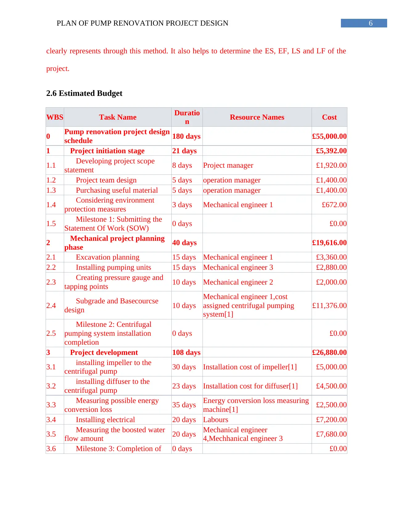
2.6 Estimated Budget
WBS Task Name Duratio
n Resource Names Cost
0 Pump renovation project design
schedule 180 days £55,000.00
1 Project initiation stage 21 days £5,392.00
1.1 Developing project scope
statement 8 days Project manager £1,920.00
1.2 Project team design 5 days operation manager £1,400.00
1.3 Purchasing useful material 5 days operation manager £1,400.00
1.4 Considering environment
protection measures 3 days Mechanical engineer 1 £672.00
1.5 Milestone 1: Submitting the
Statement Of Work (SOW) 0 days £0.00
2 Mechanical project planning
phase 40 days £19,616.00
2.1 Excavation planning 15 days Mechanical engineer 1 £3,360.00
2.2 Installing pumping units 15 days Mechanical engineer 3 £2,880.00
2.3 Creating pressure gauge and
tapping points 10 days Mechanical engineer 2 £2,000.00
2.4 Subgrade and Basecourcse
design 10 days
Mechanical engineer 1,cost
assigned centrifugal pumping
system[1]
£11,376.00
2.5
Milestone 2: Centrifugal
pumping system installation
completion
0 days £0.00
3 Project development 108 days £26,880.00
3.1 installing impeller to the
centrifugal pump 30 days Installation cost of impeller[1] £5,000.00
3.2 installing diffuser to the
centrifugal pump 23 days Installation cost for diffuser[1] £4,500.00
3.3 Measuring possible energy
conversion loss 35 days Energy conversion loss measuring
machine[1] £2,500.00
3.4 Installing electrical 20 days Labours £7,200.00
3.5 Measuring the boosted water
flow amount 20 days Mechanical engineer
4,Mechhanical engineer 3 £7,680.00
3.6 Milestone 3: Completion of 0 days £0.00
clearly represents through this method. It also helps to determine the ES, EF, LS and LF of the
project.
2.6 Estimated Budget
WBS Task Name Duratio
n Resource Names Cost
0 Pump renovation project design
schedule 180 days £55,000.00
1 Project initiation stage 21 days £5,392.00
1.1 Developing project scope
statement 8 days Project manager £1,920.00
1.2 Project team design 5 days operation manager £1,400.00
1.3 Purchasing useful material 5 days operation manager £1,400.00
1.4 Considering environment
protection measures 3 days Mechanical engineer 1 £672.00
1.5 Milestone 1: Submitting the
Statement Of Work (SOW) 0 days £0.00
2 Mechanical project planning
phase 40 days £19,616.00
2.1 Excavation planning 15 days Mechanical engineer 1 £3,360.00
2.2 Installing pumping units 15 days Mechanical engineer 3 £2,880.00
2.3 Creating pressure gauge and
tapping points 10 days Mechanical engineer 2 £2,000.00
2.4 Subgrade and Basecourcse
design 10 days
Mechanical engineer 1,cost
assigned centrifugal pumping
system[1]
£11,376.00
2.5
Milestone 2: Centrifugal
pumping system installation
completion
0 days £0.00
3 Project development 108 days £26,880.00
3.1 installing impeller to the
centrifugal pump 30 days Installation cost of impeller[1] £5,000.00
3.2 installing diffuser to the
centrifugal pump 23 days Installation cost for diffuser[1] £4,500.00
3.3 Measuring possible energy
conversion loss 35 days Energy conversion loss measuring
machine[1] £2,500.00
3.4 Installing electrical 20 days Labours £7,200.00
3.5 Measuring the boosted water
flow amount 20 days Mechanical engineer
4,Mechhanical engineer 3 £7,680.00
3.6 Milestone 3: Completion of 0 days £0.00
Paraphrase This Document
Need a fresh take? Get an instant paraphrase of this document with our AI Paraphraser
7PLAN OF PUMP RENOVATION PROJECT DESIGN
project development stage
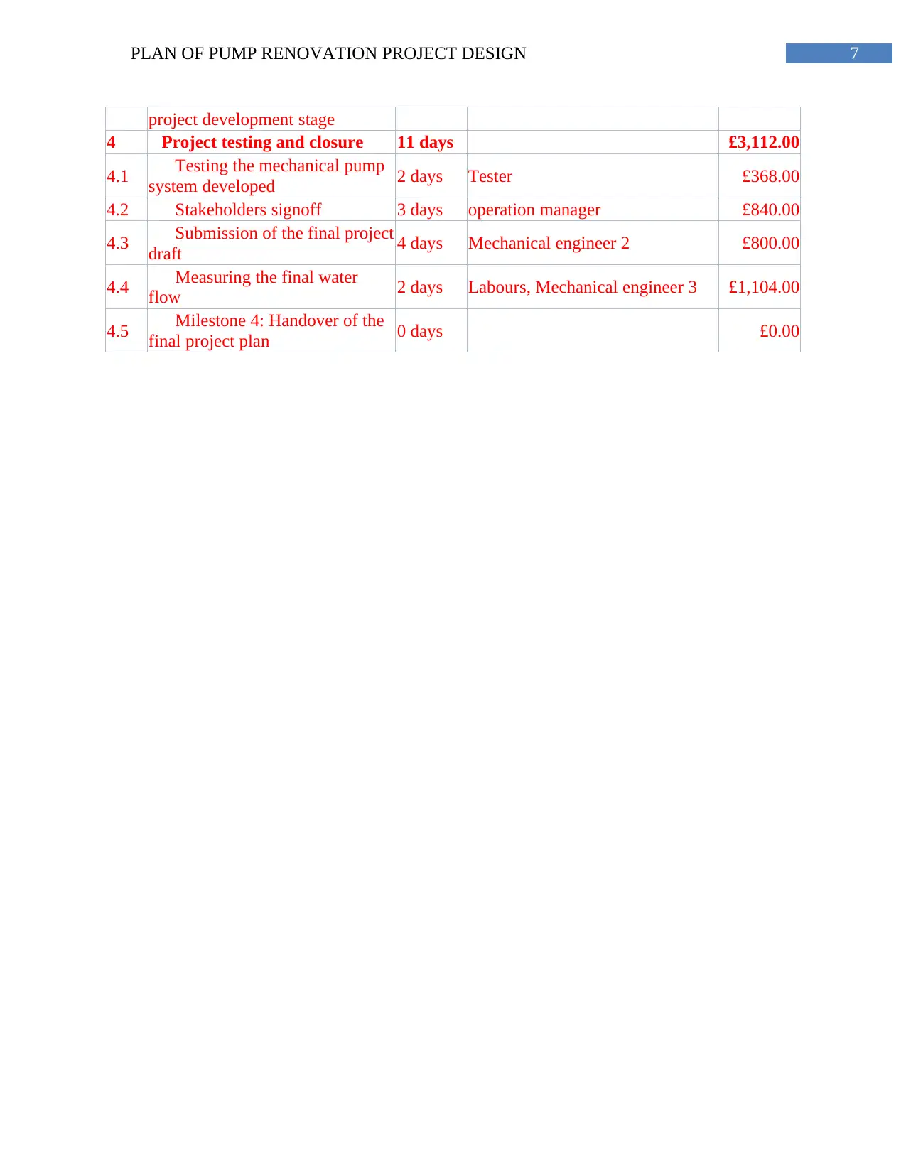
4 Project testing and closure 11 days £3,112.00
4.1 Testing the mechanical pump
system developed 2 days Tester £368.00
4.2 Stakeholders signoff 3 days operation manager £840.00
4.3 Submission of the final project
draft 4 days Mechanical engineer 2 £800.00
4.4 Measuring the final water
flow 2 days Labours, Mechanical engineer 3 £1,104.00
4.5 Milestone 4: Handover of the
final project plan 0 days £0.00
project development stage
4 Project testing and closure 11 days £3,112.00
4.1 Testing the mechanical pump
system developed 2 days Tester £368.00
4.2 Stakeholders signoff 3 days operation manager £840.00
4.3 Submission of the final project
draft 4 days Mechanical engineer 2 £800.00
4.4 Measuring the final water
flow 2 days Labours, Mechanical engineer 3 £1,104.00
4.5 Milestone 4: Handover of the
final project plan 0 days £0.00
8PLAN OF PUMP RENOVATION PROJECT DESIGN
Bibliography
Shankar, V.K.A., Umashankar, S., Paramasivam, S. and Hanigovszki, N., 2016.A comprehensive
review on energy efficiency enhancement initiatives in centrifugal pumping system. Applied
Energy, 181, pp.495-513.
Gevorkov, L., Rassõlkin, A., Kallaste, A. and Vaimann, T., 2018, January. Simulink based
model for flow control of a centrifugal pumping system. In 2018 25th International Workshop on
Electric Drives: Optimization in Control of Electric Drives (IWED) (pp. 1-4). IEEE.
Tiwari, A.K. and Kalamkar, V.R., 2018. Effects of total head and solar radiation on the
performance of solar water pumping system. Renewable Energy, 118, pp.919-927.
Gevorkov, L., Šmídl, V. and Sirový, M., 2019, June. Model of Hybrid Speed and Throttle
Control for Centrifugal Pump System Enhancement.In 2019 IEEE 28th International Symposium
on Industrial Electronics (ISIE) (pp. 563-568).IEEE.
⊘ This is a preview!⊘
Do you want full access?
Subscribe today to unlock all pages.
Trusted by 1+ million students worldwide
1 out of 12

Your All-in-One AI-Powered Toolkit for Academic Success.
+13062052269
info@desklib.com
Available 24*7 on WhatsApp / Email
![[object Object]](/_next/static/media/star-bottom.7253800d.svg)
Unlock your academic potential
Copyright © 2020–2026 A2Z Services. All Rights Reserved. Developed and managed by ZUCOL.