Mechanical Design: Shaft Calculations, Bending, and Torque Analysis
VerifiedAdded on 2020/04/01
|20
|1426
|39
Practical Assignment
AI Summary
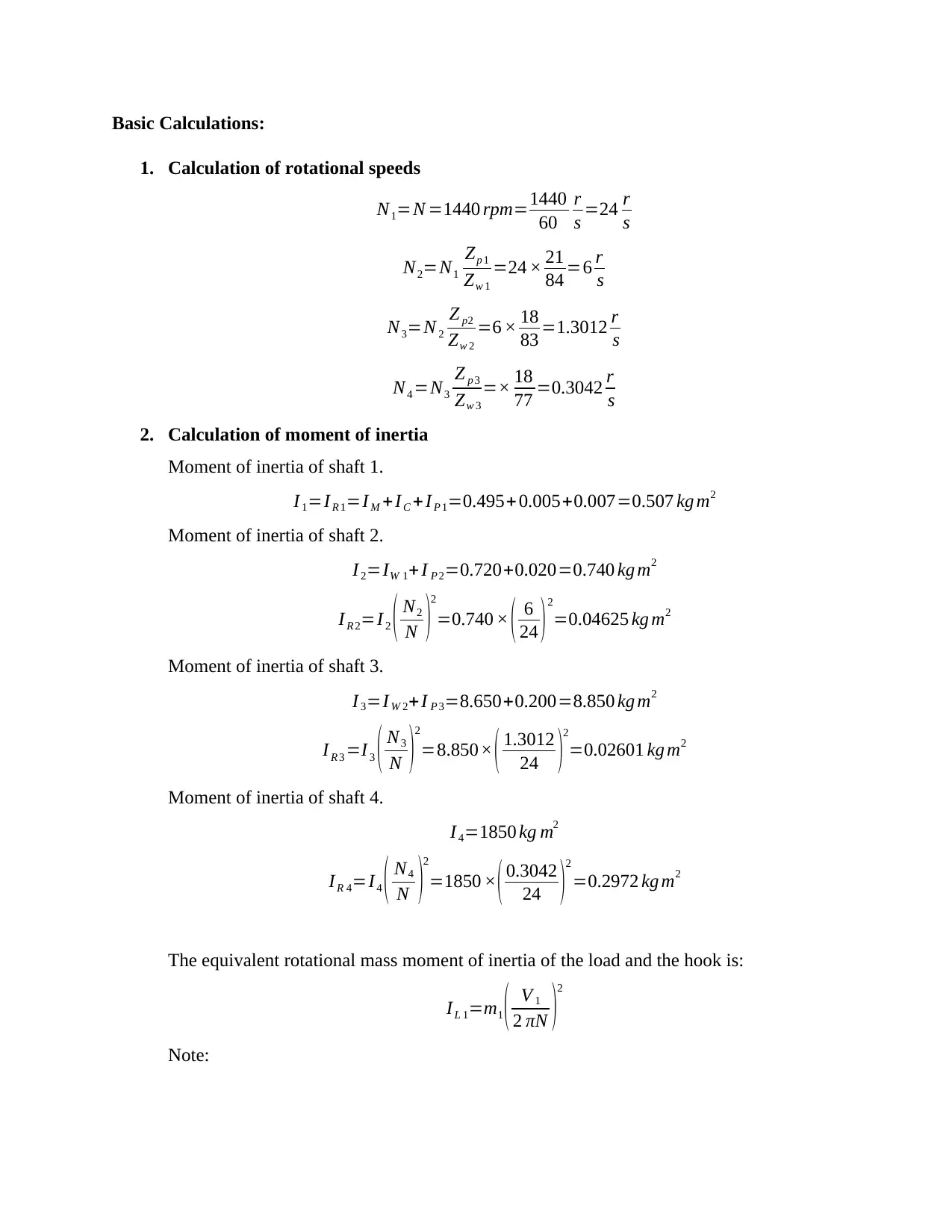
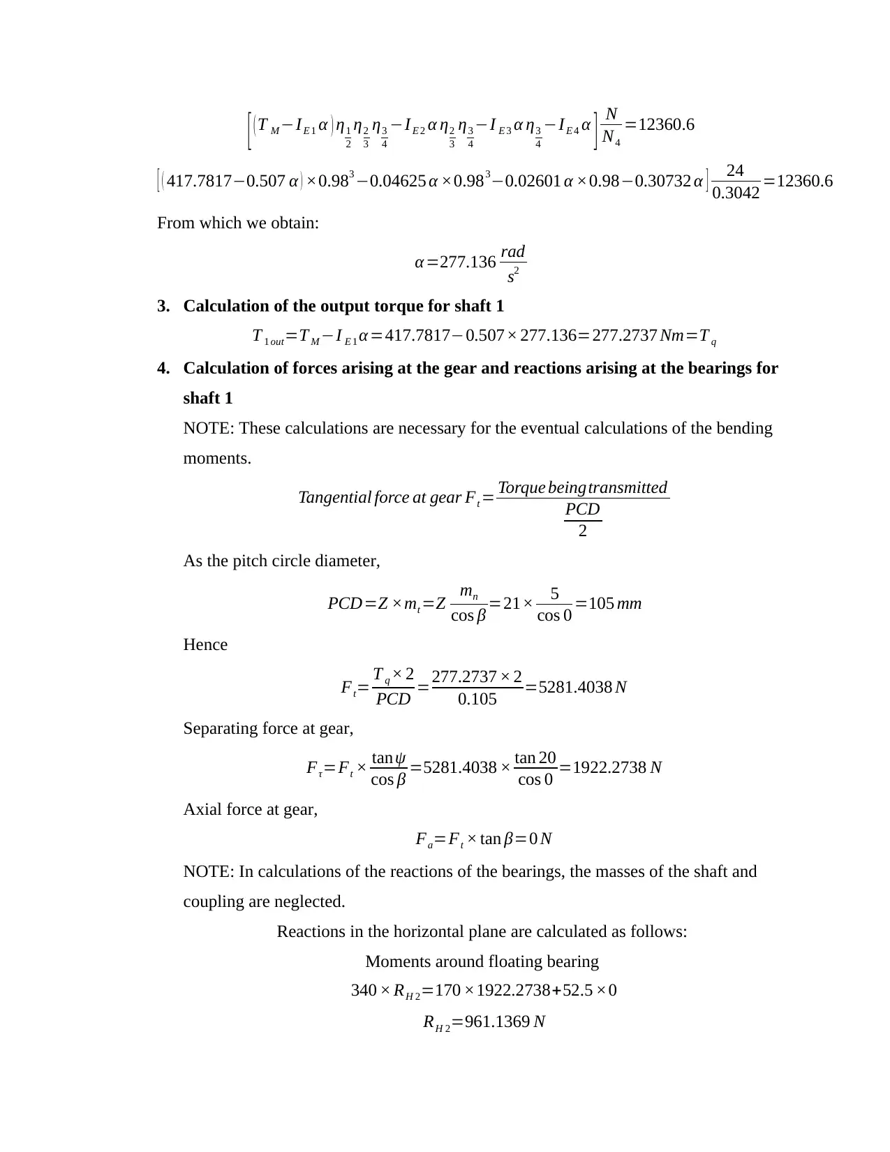
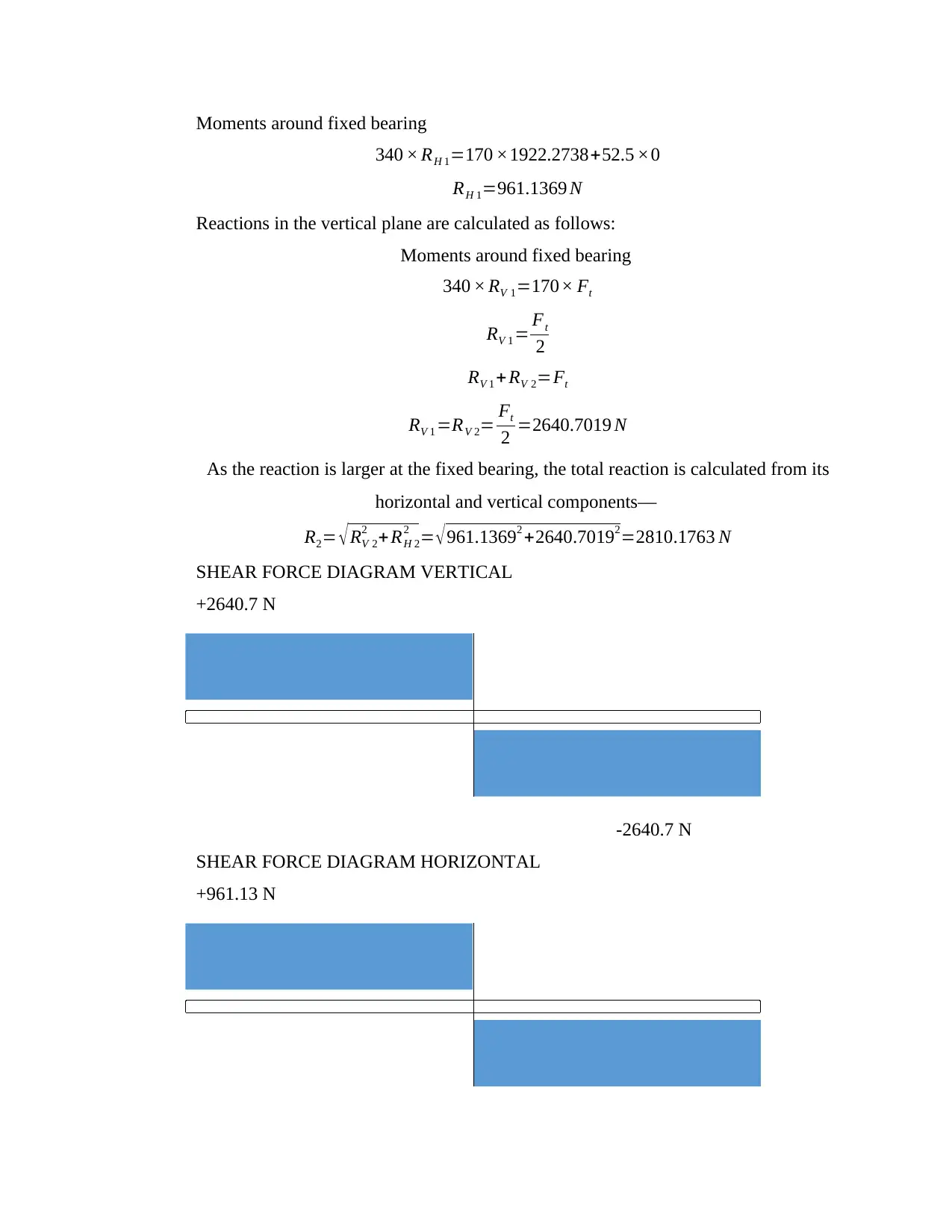
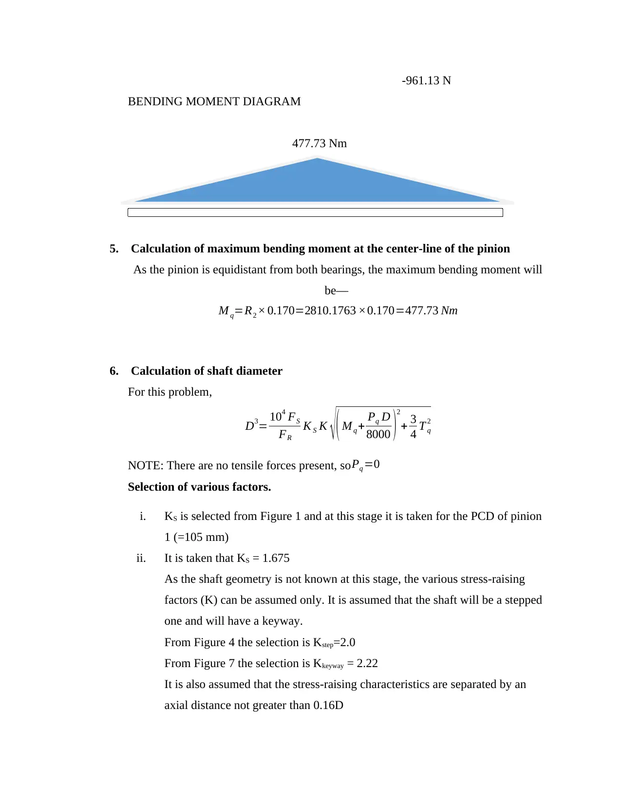
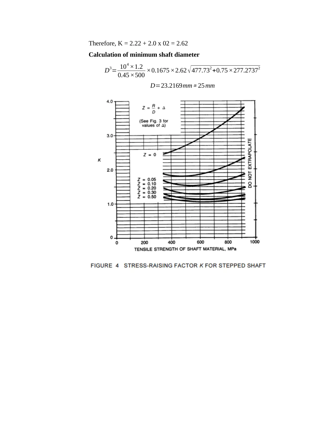
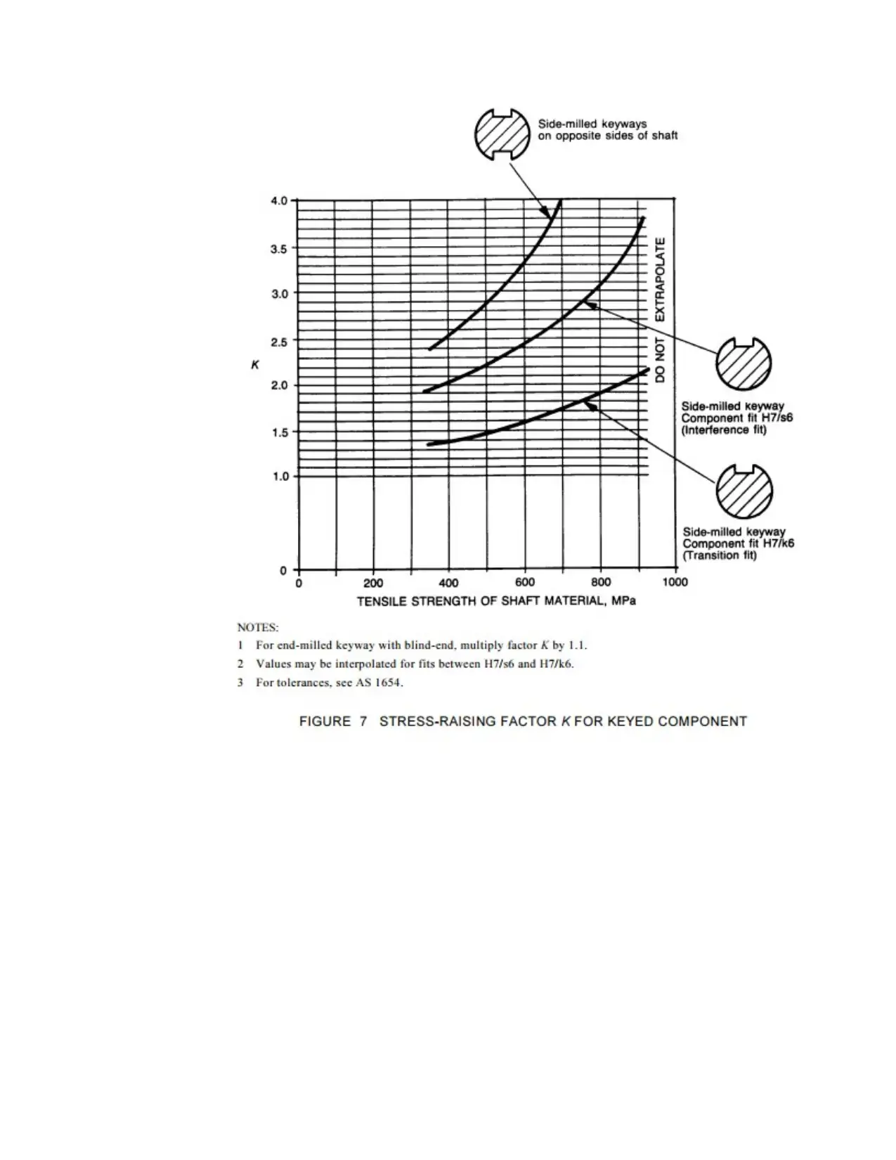
This assignment presents a comprehensive analysis of shaft design calculations for a mechanical system. It begins with the calculation of rotational speeds, moment of inertia for multiple shafts, and then proceeds to analyze the system while hoisting a maximum load. Basic torque calculations are performed, including the angular acceleration of the driving medium and the output torque for each shaft. The assignment details force calculations at gears, reactions at bearings, and shear force and bending moment diagrams. Finally, it addresses shaft diameter calculations, considering factors such as stress concentration and material properties, providing a step-by-step guide to determining the minimum shaft diameter for each shaft in the system. The document provides a detailed breakdown of each step in the design process.

Basic Calculations:
1. Calculation of rotational speeds
N1=N =1440 rpm=1440
60
r
s =24 r
s
N2=N1
Zp 1
Zw 1
=24 × 21
84 =6 r
s
N3=N 2
Z p2
Zw 2
=6 × 18
83 =1.3012 r
s
N4 =N3
Z p 3
Zw 3
=× 18
77 =0.3042 r
s
2. Calculation of moment of inertia
Moment of inertia of shaft 1.
I 1=IR 1=I M +I C +I P 1=0.495+ 0.005+0.007=0.507 kg m2
Moment of inertia of shaft 2.
I 2=IW 1+ I P 2=0.720+0.020=0.740 kg m2
I R 2=I 2 ( N2
N )
2
=0.740 × ( 6
24 ) 2
=0.04625 kg m2
Moment of inertia of shaft 3.
I 3=I W 2+I P 3=8.650+0.200=8.850 kg m2
I R 3 =I 3 ( N3
N )
2
=8.850× ( 1.3012
24 )
2
=0.02601 kg m2
Moment of inertia of shaft 4.
I 4=1850 kg m2
IR 4=I 4 ( N4
N )
2
=1850 × ( 0.3042
24 )
2
=0.2972 kg m2
The equivalent rotational mass moment of inertia of the load and the hook is:
IL 1=m1 ( V 1
2 πN )2
Note:
Secure Best Marks with AI Grader
Need help grading? Try our AI Grader for instant feedback on your assignments.

V 1=
DDRUM
2 ×2 π N 4
f = 0.3× 2 π ×0.3042
6 =0.09557 m
s
Where
f =number falls of rope=6 (assumed )
Thus
I L 1=m1 ( V 1
2 πN )
2
= ( 25000+200 ) × ( 0.09557
2 π ×24 )
2
=0.01012 kg m2
I E 4=I R 4 + I L1=0.2972+ 0.01012=0.30732 kg m2
Analysis while hoisting the maximum load
1. Basic torque calculations
Full loadtorque= Rated power ∈kilowatts× 1000
2 πN = 45 ×1000
2 π ×24
Full loadtorque=298.4155 Nm
Breakdown ( pullout ) torque=3.75 × Full load torque=1119.05582 Nm
Torque of driving motor=T M =1.4 × Full loadtorque=417.7817 Nm
2. Calculation of the angular acceleration of the driving medium.
The formula for the output torque of shaft 4 may be simplified to—
T 4 out= [ ( T M−IE 1 α ) α η1
2
η2
3
η 3
4
−I E 2 α η2
3
η 3
4
−IE 3 α η3
4
−I E 4 α ] N
N4
Because of the reeving arrangement, the static force in the rope attached to the drum is
25200× 9.81
6 N
Thus, the torque required to overcome the load resistance is—
T DRUM = 25200 ×9.81
6 × 0.3=12360.6 N
By equating the required torque and the output torque on shaft 4, i.e.T 4 out=T DRUM, we
obtain the following equation:

[ ( T M−IE 1 α ) η1
2
η2
3
η3
4
−I E 2 α η2
3
η3
4
−I E 3 α η3
4
−IE 4 α ] N
N4
=12360.6
[ ( 417.7817−0.507 α ) ×0.983 −0.04625 α ×0.983−0.02601 α ×0.98−0.30732 α ] 24
0.3042 =12360.6
From which we obtain:
α =277.136 rad
s2
3. Calculation of the output torque for shaft 1
T 1 out=T M −I E 1 α=417.7817−0.507× 277.136=277.2737 Nm=T q
4. Calculation of forces arising at the gear and reactions arising at the bearings for
shaft 1
NOTE: These calculations are necessary for the eventual calculations of the bending
moments.
Tangential force at gear Ft = Torque beingtransmitted
PCD
2
As the pitch circle diameter,
PCD=Z ×mt =Z mn
cos β =21× 5
cos 0 =105 mm
Hence
Ft= T q × 2
PCD =277.2737 × 2
0.105 =5281.4038 N
Separating force at gear,
Fτ=Ft × tanψ
cos β =5281.4038 × tan 20
cos 0 =1922.2738 N
Axial force at gear,
Fa=Ft × tan β=0 N
NOTE: In calculations of the reactions of the bearings, the masses of the shaft and
coupling are neglected.
Reactions in the horizontal plane are calculated as follows:
Moments around floating bearing
340 × RH 2=170 ×1922.2738+52.5 ×0
RH 2=961.1369 N
2
η2
3
η3
4
−I E 2 α η2
3
η3
4
−I E 3 α η3
4
−IE 4 α ] N
N4
=12360.6
[ ( 417.7817−0.507 α ) ×0.983 −0.04625 α ×0.983−0.02601 α ×0.98−0.30732 α ] 24
0.3042 =12360.6
From which we obtain:
α =277.136 rad
s2
3. Calculation of the output torque for shaft 1
T 1 out=T M −I E 1 α=417.7817−0.507× 277.136=277.2737 Nm=T q
4. Calculation of forces arising at the gear and reactions arising at the bearings for
shaft 1
NOTE: These calculations are necessary for the eventual calculations of the bending
moments.
Tangential force at gear Ft = Torque beingtransmitted
PCD
2
As the pitch circle diameter,
PCD=Z ×mt =Z mn
cos β =21× 5
cos 0 =105 mm
Hence
Ft= T q × 2
PCD =277.2737 × 2
0.105 =5281.4038 N
Separating force at gear,
Fτ=Ft × tanψ
cos β =5281.4038 × tan 20
cos 0 =1922.2738 N
Axial force at gear,
Fa=Ft × tan β=0 N
NOTE: In calculations of the reactions of the bearings, the masses of the shaft and
coupling are neglected.
Reactions in the horizontal plane are calculated as follows:
Moments around floating bearing
340 × RH 2=170 ×1922.2738+52.5 ×0
RH 2=961.1369 N

Moments around fixed bearing
340 × RH 1=170 ×1922.2738+52.5 ×0
RH 1=961.1369 N
Reactions in the vertical plane are calculated as follows:
Moments around fixed bearing
340 × RV 1=170× Ft
RV 1 = Ft
2
RV 1 + RV 2=Ft
RV 1 =RV 2= Ft
2 =2640.7019 N
As the reaction is larger at the fixed bearing, the total reaction is calculated from its
horizontal and vertical components—
R2= √ RV 2
2 + RH 2
2 = √ 961.13692 +2640.70192=2810.1763 N
SHEAR FORCE DIAGRAM VERTICAL
+2640.7 N
-2640.7 N
SHEAR FORCE DIAGRAM HORIZONTAL
+961.13 N
Secure Best Marks with AI Grader
Need help grading? Try our AI Grader for instant feedback on your assignments.

-961.13 N
BENDING MOMENT DIAGRAM
477.73 Nm
5. Calculation of maximum bending moment at the center-line of the pinion
As the pinion is equidistant from both bearings, the maximum bending moment will
be—
M q=R2 × 0.170=2810.1763 ×0.170=477.73 Nm
6. Calculation of shaft diameter
For this problem,
D3= 104 FS
FR
K S K √( M q + Pq D
8000 )2
+ 3
4 T q
2
NOTE: There are no tensile forces present, so Pq =0
Selection of various factors.
i. KS is selected from Figure 1 and at this stage it is taken for the PCD of pinion
1 (=105 mm)
ii. It is taken that KS = 1.675
As the shaft geometry is not known at this stage, the various stress-raising
factors (K) can be assumed only. It is assumed that the shaft will be a stepped
one and will have a keyway.
From Figure 4 the selection is Kstep=2.0
From Figure 7 the selection is Kkeyway = 2.22
It is also assumed that the stress-raising characteristics are separated by an
axial distance not greater than 0.16D

Therefore, K = 2.22 + 2.0 x 02 = 2.62
Calculation of minimum shaft diameter
D3= 104 ×1.2
0.45 ×500 ×0.1675 ×2.62 √477.732 +0.75 ×277.27372
D=23.2169mm ≅ 25 mm
Calculation of minimum shaft diameter
D3= 104 ×1.2
0.45 ×500 ×0.1675 ×2.62 √477.732 +0.75 ×277.27372
D=23.2169mm ≅ 25 mm

Paraphrase This Document
Need a fresh take? Get an instant paraphrase of this document with our AI Paraphraser

1. Calculation of the output torque for shaft 2
T 1 out=T M −I E 2 α=417.7817−0.74 ×277.136=212.701 Nm=T q
2. Calculation of forces arising at the gear and reactions arising at the bearings for
shaft 1
NOTE: These calculations are necessary for the eventual calculations of the bending
moments.
Tangential force at gear Ft = Torque beingtransmitted
PCD
2
As the pitch circle diameter,
PCD=Z ×mt =Z mn
cos β =84 × 5
cos 0 =420 mm
Hence
Ft= T q × 2
PCD =212.701 ×2
0.42 =1012.861 N
Separating force at gear,
Fτ=Ft × tanψ
cos β =1012.861 × tan 20
cos 0 =368.651 N
Axial force at gear,
Fa=Ft × tan β=0 N
NOTE: In calculations of the reactions of the bearings, the masses of the shaft and
coupling are neglected.
Reactions in the horizontal plane are calculated as follows:
Moments around floating bearing
340 × RH 2=170 ×368.651+52.5 ×0
RH 2=184.3255 N
Moments around fixed bearing
340 × RH 1=170 ×368.651+52.5× 0
RH 1=184.3255 N

Reactions in the vertical plane are calculated as follows:
Moments around fixed bearing
340 × RV 1=170× Ft
RV 1 = Ft
2
RV 1 + RV 2=Ft
RV 1 =RV 2= Ft
2 =506.4305 N
As the reaction is larger at the fixed bearing, the total reaction is calculated from its
horizontal and vertical components—
R2= √ RV 2
2 + RH 2
2 = √ 506.43052 +184.32552=538.932 N
3. Calculation of maximum bending moment at the center-line of the pinion
As the pinion is equidistant from both bearings, the maximum bending moment will
be—
M q=R2 × 0.170=538.932 ×0.170=91.618 Nm
SHEAR FORCE DIAGRAM VERTICAL
+506.43 N
-506.43 N

SHEAR FORCE DIAGRAM HORIZONTAL
+184.32 N
-184.32 N
BENDING MOMENT DIAGRAM
91.618 Nm
4. Calculation of shaft diameter
For this problem,
D3= 104 FS
FR
K S K √( M q + Pq D
8000 )2
+ 3
4 T q
2
NOTE: There are no tensile forces present, soPq =0
Selection of various factors.
iii. KS is selected from Figure 1 and at this stage it is taken for the PCD of pinion
1 (=105 mm)
iv. It is taken that KS = 1.675
As the shaft geometry is not known at this stage, the various stress-raising
factors (K) can be assumed only. It is assumed that the shaft will be a stepped
one and will have a keyway.
Secure Best Marks with AI Grader
Need help grading? Try our AI Grader for instant feedback on your assignments.

From Figure 4 the selection is Kstep=2.0
From Figure 7 the selection is Kkeyway = 2.22
It is also assumed that the stress-raising characteristics are separated by an
axial distance not greater than 0.16D
Therefore, K = 2.22 + 2.0 x 02 = 2.62
Calculation of minimum shaft diameter
D3= 104 ×1.2
0.45 ×500 ×0.1675 ×2.62 √ 91.6182+ 0.75 ×212.7012
D=48.151 mm≅ 50 mm


1. Calculation of the output torque for shaft 3
T 1 out=T M−I E 3 α=417.7817−.885× 277.136=172.516 Nm=Tq
2. Calculation of forces arising at the gear and reactions arising at the bearings for
shaft 1
NOTE: These calculations are necessary for the eventual calculations of the bending
moments.
Tangential force at gear Ft = Torque beingtransmitted
PCD
2
As the pitch circle diameter,
PCD=Z ×mt =Z mn
cos β =83× 7
cos 0 =581 mm
Hence
Ft= T q × 2
PCD =172.516 × 2
0.581 =593.85 N
Separating force at gear,
Fτ=Ft × tanψ
cos β =593.85 × tan 20
cos 0 =216.143 N
Axial force at gear,
Fa=Ft × tan β=0 N
NOTE: In calculations of the reactions of the bearings, the masses of the shaft and
coupling are neglected.
Reactions in the horizontal plane are calculated as follows:
Moments around floating bearing
340 × RH 2=170 ×216.143+52.5 ×0
RH 2=108.071 N
Moments around fixed bearing
340 × RH 1=170 ×216.143+52.5 ×0
RH 1=108.071 N
Paraphrase This Document
Need a fresh take? Get an instant paraphrase of this document with our AI Paraphraser

Reactions in the vertical plane are calculated as follows:
Moments around fixed bearing
340 × RV 1=170× Ft
RV 1 = Ft
2
RV 1 + RV 2=Ft
RV 1 =RV 2= Ft
2 =296.925 N
As the reaction is larger at the fixed bearing, the total reaction is calculated from its
horizontal and vertical components—
R2= √ RV 2
2 + RH 2
2 = √ 296.9252 +108.0712=315.98 N
3. Calculation of maximum bending moment at the center-line of the pinion
As the pinion is equidistant from both bearings, the maximum bending moment will
be—
M q=R2 × 0.170=315.98 ×0.170=53.7166 Nm
SHEAR FORCE DIAGRAM VERTICAL
+296.92 N
-296.92 N

SHEAR FORCE DIAGRAM HORIZONTAL
+108.07 N
-108.07 N
BENDING MOMENT DIAGRAM
53.71 Nm
4. Calculation of shaft diameter
For this problem,
D3= 104 FS
FR
K S K √( M q + Pq D
8000 )2
+ 3
4 T q
2
NOTE: There are no tensile forces present, soPq =0
Selection of various factors.
v. KS is selected from Figure 1 and at this stage it is taken for the PCD of pinion
1 (=105 mm)
vi. It is taken that KS = 1.675
As the shaft geometry is not known at this stage, the various stress-raising
factors (K) can be assumed only. It is assumed that the shaft will be a stepped
one and will have a keyway.

From Figure 4 the selection is Kstep=2.0
From Figure 7 the selection is Kkeyway = 2.22
It is also assumed that the stress-raising characteristics are separated by an
axial distance not greater than 0.16D
Therefore, K = 2.22 + 2.0 x 02 = 2.62
Calculation of minimum shaft diameter
D3= 104 ×1.2
0.45 ×500 ×0.1675 ×2.62 √53.7162+ 0.75× 172.5162
D=47.151 mm≅ 50 mm
Secure Best Marks with AI Grader
Need help grading? Try our AI Grader for instant feedback on your assignments.

1. Calculation of the output torque for shaft 4
T 1 out=T M −I E 3 α=417.7817−.307× 277.136=332.7 Nm=T q
2. Calculation of forces arising at the gear and reactions arising at the bearings for
shaft 1
NOTE: These calculations are necessary for the eventual calculations of the bending
moments.
Tangential force at gear Ft = Torque beingtransmitted
PCD
2
As the pitch circle diameter,Given
PCD=600 mm
Hence
Ft= T q × 2
PCD =332.7 × 2
0.6 =1109 N
Separating force at gear,
Fτ=Ft × tanψ
cos β =1109 × tan 20
cos 0 =403.64 N
Axial force at gear,
Fa=Ft × tan β=0 N
NOTE: In calculations of the reactions of the bearings, the masses of the shaft and
coupling are neglected.
Reactions in the horizontal plane are calculated as follows:
Moments around floating bearing
1400 × RH 2=200 ×403.64 +52.5 ×0
RH 2=57.66 N
Moments around fixed bearing
1400 × RH 1=200 ×403.64 +52.5 ×0
RH 1=57.66 N

Reactions in the vertical plane are calculated as follows:
Moments around fixed bearing
340 × RV 1=170× Ft
RV 1 = Ft
2
RV 1 + RV 2=Ft
RV 1 =RV 2= Ft
2 =554.5 N
As the reaction is larger at the fixed bearing, the total reaction is calculated from its
horizontal and vertical components—
R2= √ RV 2
2 + RH 2
2 = √ 554.52 +57.662=557.48 N
3. Calculation of maximum bending moment at the center-line of the pinion
As the pinion is equidistant from both bearings, the maximum bending moment will
be—
M q=R2 × 0.170=557.48 ×0.20=111.49 Nm
SHEAR FORCE DIAGRAM VERTICAL
+554.5 N
-554.5 N

SHEAR FORCE DIAGRAM HORIZONTAL
+57.6 N
-57.6 N
BENDING MOMENT DIAGRAM
111.49 Nm
4. Calculation of shaft diameter
For this problem,
D3= 104 FS
FR
K S K √( M q + Pq D
8000 )2
+ 3
4 T q
2
NOTE: There are no tensile forces present, soPq =0
Selection of various factors.
vii. KS is selected from Figure 1 and at this stage it is taken for the PCD of pinion
1 (=105 mm)
viii. It is taken that KS = 1.675
As the shaft geometry is not known at this stage, the various stress-raising
Paraphrase This Document
Need a fresh take? Get an instant paraphrase of this document with our AI Paraphraser

factors (K) can be assumed only. It is assumed that the shaft will be a stepped
one and will have a keyway.
From Figure 4 the selection is Kstep=2.0
From Figure 7 the selection is Kkeyway = 2.22
It is also assumed that the stress-raising characteristics are separated by an
axial distance not greater than 0.16D
Therefore, K = 2.22 + 2.0 x 02 = 2.62
Calculation of minimum shaft diameter
D3= 104 ×1.2
0.45 ×500 ×0.1675 ×2.62 √111.492+0.75× 332.72
D=23.54 mm ≅ 25 mm
1 out of 20

Your All-in-One AI-Powered Toolkit for Academic Success.
+13062052269
info@desklib.com
Available 24*7 on WhatsApp / Email
Unlock your academic potential
© 2024 | Zucol Services PVT LTD | All rights reserved.