Mechanical Engineering Project: Data Processing and Analysis

Verified

Added on  2020/05/03

|8
|1071
|119
Project
AI Summary
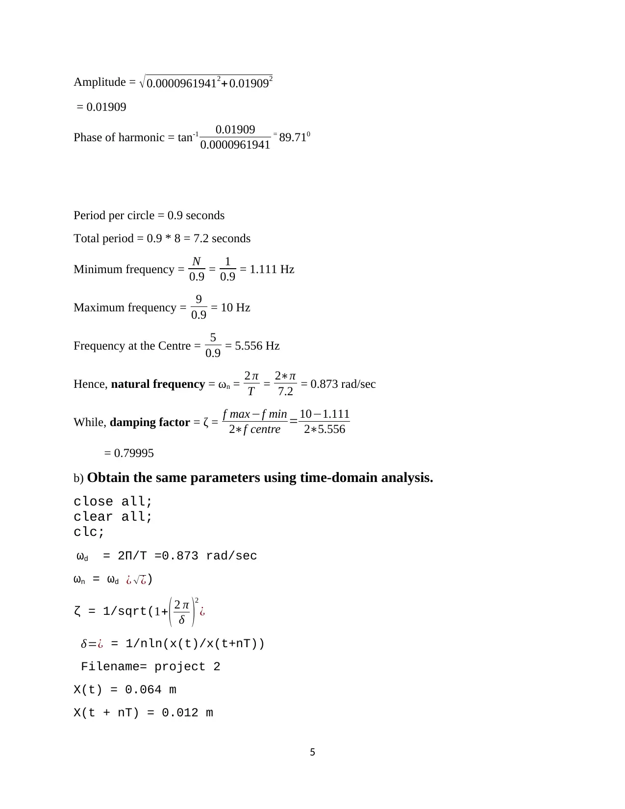
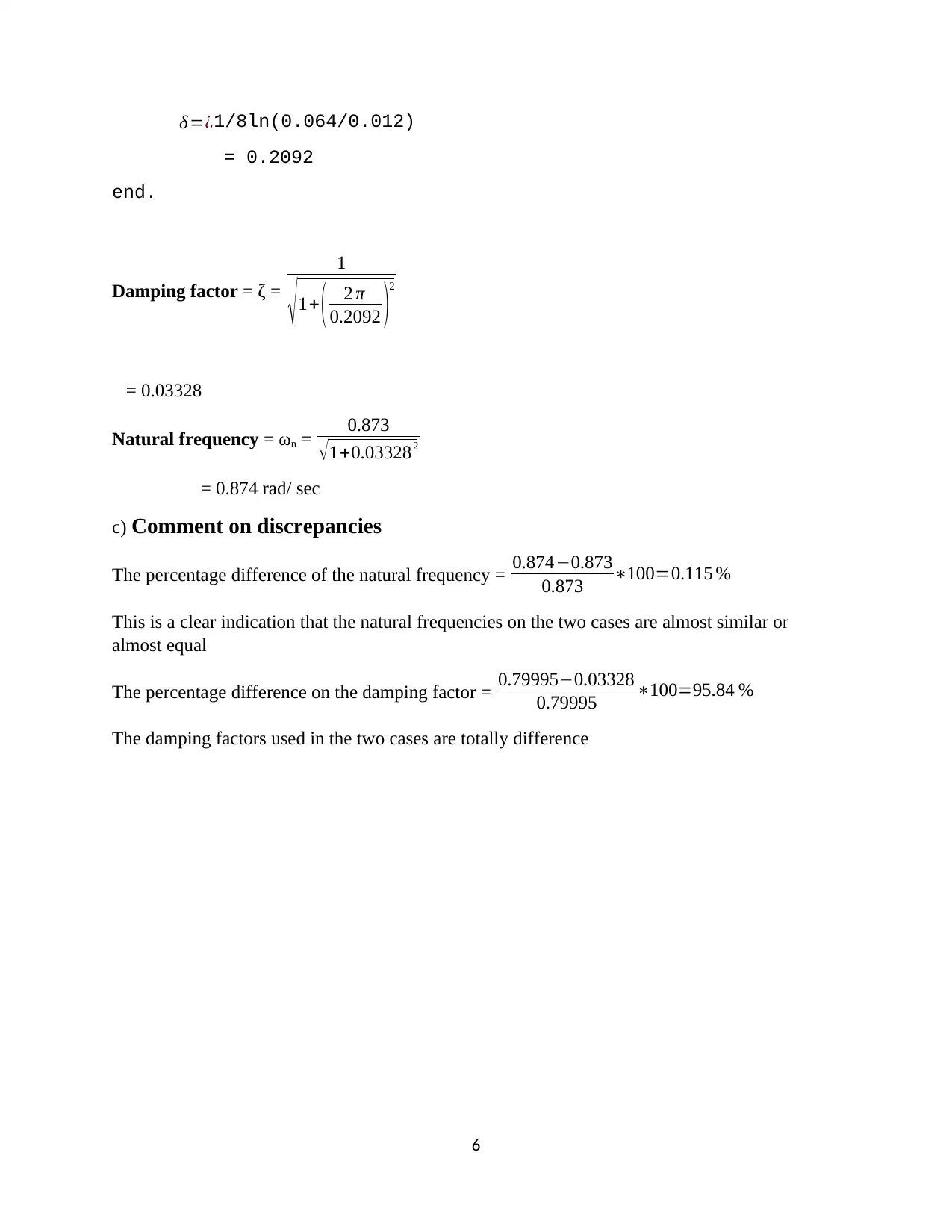
This project analyzes the dynamic characteristics of a mechanical system, likely a passenger vehicle, using data processing and analysis techniques. The solution begins by presenting the governing differential equation of motion and then employs Fourier Transforms to estimate the system's natural frequency and damping factor. The project outlines the steps for setting up and solving the equation, including the use of MATLAB code to simulate the system's response. The solution then calculates the natural frequency and damping factor using time-domain analysis and compares the results obtained from both methods, highlighting any discrepancies. The project also includes references to relevant literature on mechanical vibration and shock, providing context for the analysis. The assignment demonstrates the application of different analysis methods to determine the key parameters of a vibrating system.
tabler-icon-diamond-filled.svg

Contribute Materials

Your contribution can guide someone’s learning journey. Share your documents today.
Document Page
Project 1
Data processing and analysis:
Note; ωn = 1
LC
While; ζ = 1
2 R C
L
Then, ω 2ω 1
ωn =2ζ
¨V 0 + 2ζωn ˙v0+ v0ωn2 = 2 ζωn ˙vn
¨V 0 = 1
δ t2 [v0i+2 -2v0i+1 + v0i]
= 1
δt [v0i+1 - v0i]
δt = 1
Fs
Hence, ωn = 2 πf n
Therefore; ωn *δt = 2 πfn
fn
v0i+2 = v0i+1(2-2ζ* 2 πfn
fn ) – vo0(1-2ζ* 2 πfn
fn + ( 2 πfn
fn )2 + 2ζ( 2 πfn
fn )(Vni+1 – Vni)
where; i= 0 N 1
a) Use Fourier Transforms to estimate the natural frequency of the system
and its damping factor.
Mx + cx + kx = fsinωt………………………………(1)
From the calculation below
1
tabler-icon-diamond-filled.svg

Secure Best Marks with AI Grader

Need help grading? Try our AI Grader for instant feedback on your assignments.
Document Page
The value of ζ = 0.79995
While ω = 0.873
Lets take the passanger vehicle has a weight of; f = 10000 N
While x(0) = 0.064 and x(0) = 0
The above equation is similar to the unforced system except that it has a forcing function.
To solve this equation we have to reduce it into first order differential equation
Let
x = v ………………..(2)
but
v = [(f/m)sinωt – (c/m)v – (k/m)x] ……….(3)
the second order differential equation has been reduced to the first order differential equation
therefore;
x = y(1)
x = v = y(2)
equation (2) and (3) then reduced to
y(1) = y(2)
y(2) = [(f/m)sin(ωt) + (-c/m)*y(2) – (k/m)*y(1)]
to calculate for the value of c
we compaire equation (1) with the following generalized equation
x + 2ζωn + ωn2 = fsinωt
equating the coefficient
c/m = 2ζωn
ωn2 = k/m
from the calculation below
ωd = 0.873 rad/sec
2
Document Page
ωn = 0.874 rad/sec
ζ = 0.03328
damped time period Td = 2πd = 7.2 sec
for 5 time cycle the interval should be 36 sec, since the plot should indicate both the transient
and steady state responses, the time interval will be increased
function yp = forced(t,y)
yp = (y(2);(((f/m)*sin(ωn*t))-((c/m*y(2))-(k/m)*y(1))));
The following code represent the main code
span = (0 5);
y0=(0.064;0);
(t,y)=ode45(forced,tspan,y0);
Plot(t,y(:,1));
grid on
xlabel(time)
ylabel(Displacement)
title(Displacement vs time)
hold on
tspan represent the time interval and y0 represent the initial condition for y(1) and y(2), which in
turn represent the displacement x and the first derivative f x
3
Document Page
A0 = 2
N
n=1
N
X ncos ¿ 2 π
N
=
2
N [0.064cos 2 π
8 +0.052cos 2 π2
8 +0.042cos 2 π3
8 + 0.034cos 2 π4
8 +0.028cos 2 π5
8 + 0.022cos 2 π6
8
= 0.0000961941
B0 = 2
N
n=1
N
X ncos ¿ 2 π
N
=
2
N [0.064sin 2 π
8 +0.052sin 2 π2
8 + 0.042sin 2 π3
8 + 0.034sin 2 π4
8 +0.028sin 2 π5
8 +0.022sin 2 π6
8 +
= 0.01909
4
tabler-icon-diamond-filled.svg

Secure Best Marks with AI Grader

Need help grading? Try our AI Grader for instant feedback on your assignments.
Document Page
Amplitude = 0.00009619412+ 0.019092
= 0.01909
Phase of harmonic = tan-1 0.01909
0.0000961941 = 89.710
Period per circle = 0.9 seconds
Total period = 0.9 * 8 = 7.2 seconds
Minimum frequency = N
0.9 = 1
0.9 = 1.111 Hz
Maximum frequency = 9
0.9 = 10 Hz
Frequency at the Centre = 5
0.9 = 5.556 Hz
Hence, natural frequency = ωn = 2 π
T = 2π
7.2 = 0.873 rad/sec
While, damping factor = ζ = f maxf min
2f centre =101.111
25.556
= 0.79995
b) Obtain the same parameters using time-domain analysis.
close all;
clear all;
clc;
ωd = 2П/T =0.873 rad/sec
ωn = ωd ¿ ¿)
ζ = 1/sqrt(1+( 2 π
δ )
2
¿
δ=¿ = 1/nln(x(t)/x(t+nT))
Filename= project 2
X(t) = 0.064 m
X(t + nT) = 0.012 m
5
Document Page
δ=¿1/8ln(0.064/0.012)
= 0.2092
end.
Damping factor = ζ =
1
1+ ( 2 π
0.2092 )2
= 0.03328
Natural frequency = ωn = 0.873
1+0.033282
= 0.874 rad/ sec
c) Comment on discrepancies
The percentage difference of the natural frequency = 0.8740.873
0.873 100=0.115 %
This is a clear indication that the natural frequencies on the two cases are almost similar or
almost equal
The percentage difference on the damping factor = 0.799950.03328
0.79995 100=95.84 %
The damping factors used in the two cases are totally difference
6
Document Page
References
AV-010, c. (2013). mechanical vibration and shock human effect. Sydney: SAI Global limited .
W. Hugemann and M. Nicke, “Longitudinal and lateral accelerations in normal day driving,”
in Proceedings of the Institute of Traffic Accident Investigators Conference (ITAI '03), E. J. Allen, Ed., pp.
1–8, Croydon, UK, 2003
X. D. Pan, T. Lin, and Z. Yang, “Relationship between the variation of drivers' heart rate and systolic
blood pressure and the coefficient of transverse force of mountainous highways,” Journal of Tongji
University, vol. 34, no. 6, pp. 748–751, 2006.
W. J. Cheng, Study on the evaluation method of highway alignment comfortableness [M.S. thesis], Hebei
University of Technology, Tianjin, China, 2007.
C. Tan, An investigation of comfortable lateral acceleration on horizontal curves [Ph.D. dissertation],
Pennsylvania State University, State College, Pa, USA, 2003.
"Application of Integrated-Circuit Electronics to Piezoelectric Transducers." March 1967. PCB
Piezotronics, #G-01.
"Isotron Instruction Manual." 1995. Endevco, IM 31704.
"Instruction Manual for Endevco Piezoresistive Accelerometers." 1978. Endevco, #121.
"Entran Accelerometer Instruction and Selection Manual." 1987. Entran Devices.
R. Sill. "Testing Techniques Involved with the Development of High Shock Acceleration Sensors."
Endevco, TP 284.
R. Sill. "Minimizing Measurement Uncertainty in Calibration and Use of Accelerometers." Endevco, TP
299.
P.K. Stein. "The Constant Current Concept for Dynamic Strain Measurement." Stein Engineering Services,
Inc., Lf/MSE Publication 46.
B. Link. "Shock and Vibration Measurement Using Variable Capacitance." Endevco, TP 296.
7
tabler-icon-diamond-filled.svg

Paraphrase This Document

Need a fresh take? Get an instant paraphrase of this document with our AI Paraphraser
Document Page
8
chevron_up_icon
1 out of 8
circle_padding
hide_on_mobile
zoom_out_icon
logo.png

Your All-in-One AI-Powered Toolkit for Academic Success.

Available 24*7 on WhatsApp / Email

[object Object]