Mechanical Principles: Analysis of Static, Dynamic, and Power Systems
VerifiedAdded on 2023/06/05
|19
|1935
|80
Report
AI Summary
This report provides a comprehensive analysis of mechanical principles, encompassing static and dynamic mechanical systems, power transmission, and damped vibrations. It includes calculations of shear force, bending moments, and stress distribution in simply supported beams, along with the justification for selecting standard rolled steel sections. The report delves into experimental data from torsion tests to determine the material of a circular bar and calculates shear force and bending moments in cantilever and encastre systems. Furthermore, it explains energy transfer, gyroscopic reaction torque, and velocity/acceleration solutions in planar mechanisms. The report also covers the determination of velocity ratios in compound gear systems, the operating efficiency of lead screws, and conditions for constant velocity ratios. Finally, it explores natural frequencies in mass-spring systems, transient response analysis, and the conditions and prevention of material resonance, providing a complete overview of key mechanical engineering concepts. This assignment is contributed by a student to be published on the website Desklib. Desklib is a platform which provides all the necessary AI based study tools for students.
Mechanical Principles 1
Mechanical Principles
by Student’s Name
Code + Course Name
Professor’s Name
University Name
City, State
Date
Mechanical Principles
by Student’s Name
Code + Course Name
Professor’s Name
University Name
City, State
Date
Paraphrase This Document
Need a fresh take? Get an instant paraphrase of this document with our AI Paraphraser
Mechanical Principles 2
Task 1: Static Mechanical System
Section 1: For Shear force, bending moments and stress due to bending calculate the
distribution into simply supported beam.
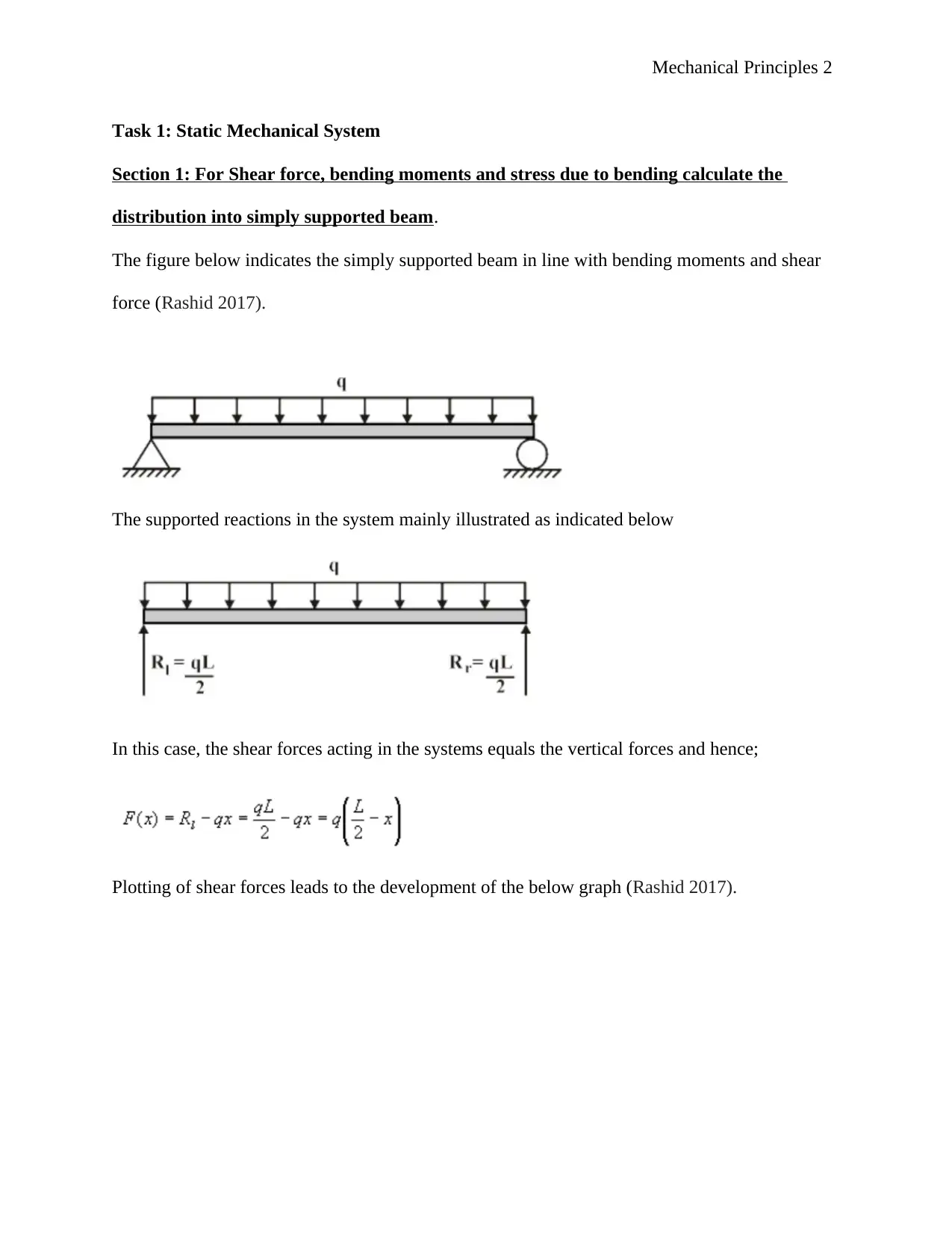
The figure below indicates the simply supported beam in line with bending moments and shear
force (Rashid 2017).
The supported reactions in the system mainly illustrated as indicated below
In this case, the shear forces acting in the systems equals the vertical forces and hence;
Plotting of shear forces leads to the development of the below graph (Rashid 2017).
Mechanical Principles 3
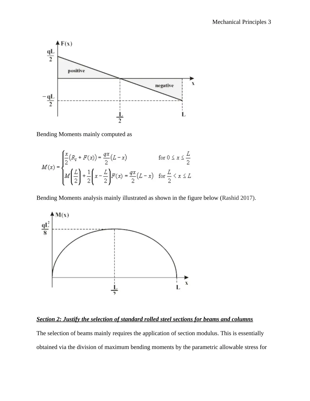
Bending Moments mainly computed as
Bending Moments analysis mainly illustrated as shown in the figure below (Rashid 2017).
Section 2: Justify the selection of standard rolled steel sections for beams and columns
The selection of beams mainly requires the application of section modulus. This is essentially
obtained via the division of maximum bending moments by the parametric allowable stress for
⊘ This is a preview!⊘
Do you want full access?
Subscribe today to unlock all pages.

Trusted by 1+ million students worldwide
Mechanical Principles 4
the standard rolled steel. However, there is need to have allowable safety factor. The equation for
the analysis mainly given as shown below
Tensions as well as compressional forces are essential factors to be incorporated in the analysis.
In essence, the allowable stresses mainly established to be the same in the event that there is a
cross-sectional area which tends to go through the parametric center of the neutral axis beam
height. The weight minimization in a beam slab mainly attained by using the beam elements with
the both the smallest mass and cross-sectional area. Another important criterion is how often the
material buckles and thus, is defined by the application of the slenderness ratio. The equation for
the norm mainly appraised as indicated below
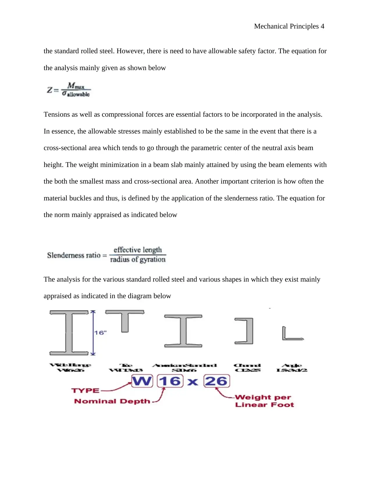
The analysis for the various standard rolled steel and various shapes in which they exist mainly
appraised as indicated in the diagram below
Paraphrase This Document
Need a fresh take? Get an instant paraphrase of this document with our AI Paraphraser
Mechanical Principles 5
Section 3: Determine the material of a circular bar from experimental data of angle of twist
obtained from a torsion test.
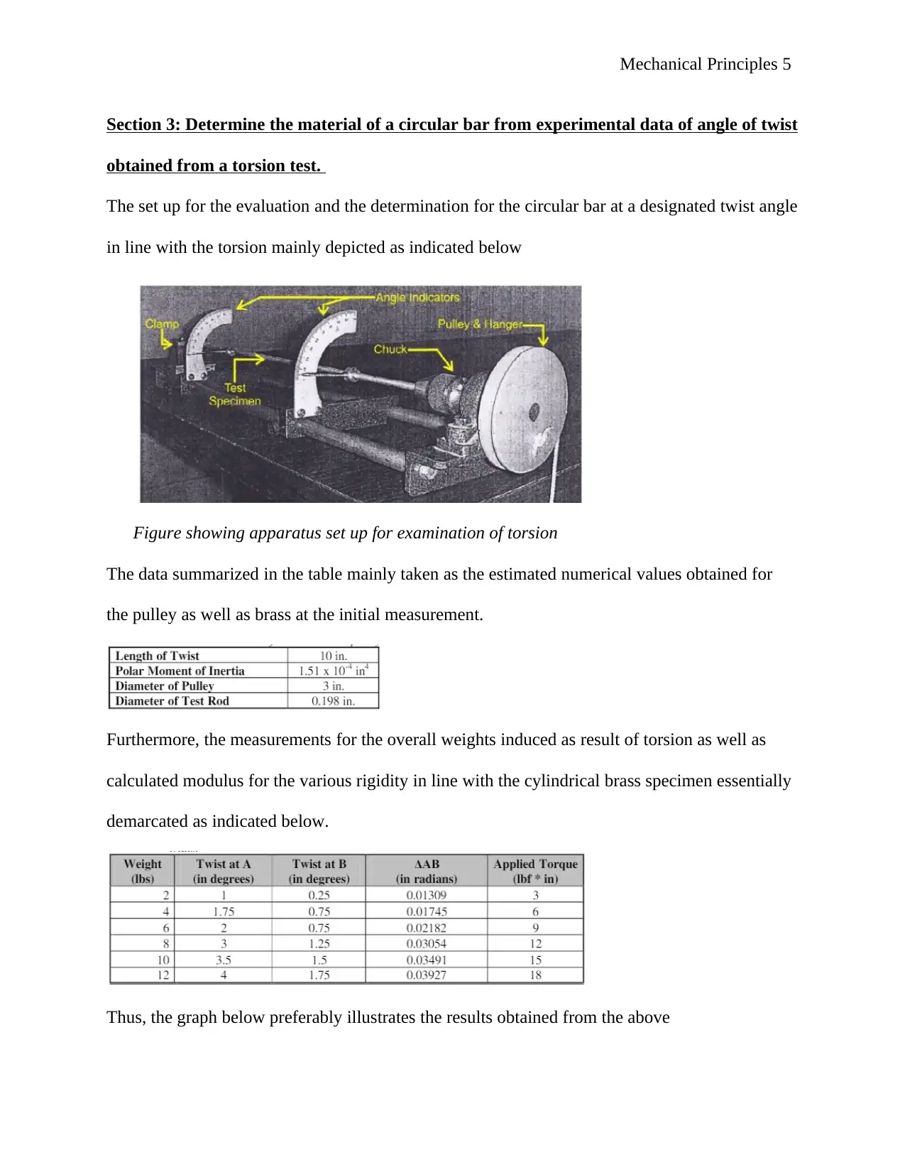
The set up for the evaluation and the determination for the circular bar at a designated twist angle
in line with the torsion mainly depicted as indicated below
Figure showing apparatus set up for examination of torsion
The data summarized in the table mainly taken as the estimated numerical values obtained for
the pulley as well as brass at the initial measurement.
Furthermore, the measurements for the overall weights induced as result of torsion as well as
calculated modulus for the various rigidity in line with the cylindrical brass specimen essentially
demarcated as indicated below.
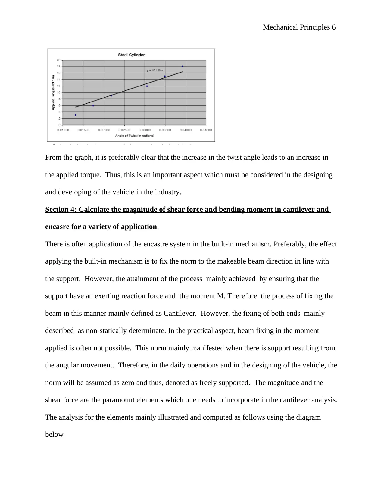
Thus, the graph below preferably illustrates the results obtained from the above
Mechanical Principles 6
From the graph, it is preferably clear that the increase in the twist angle leads to an increase in
the applied torque. Thus, this is an important aspect which must be considered in the designing
and developing of the vehicle in the industry.
Section 4: Calculate the magnitude of shear force and bending moment in cantilever and
encasre for a variety of application.
There is often application of the encastre system in the built-in mechanism. Preferably, the effect
applying the built-in mechanism is to fix the norm to the makeable beam direction in line with
the support. However, the attainment of the process mainly achieved by ensuring that the
support have an exerting reaction force and the moment M. Therefore, the process of fixing the
beam in this manner mainly defined as Cantilever. However, the fixing of both ends mainly
described as non-statically determinate. In the practical aspect, beam fixing in the moment
applied is often not possible. This norm mainly manifested when there is support resulting from
the angular movement. Therefore, in the daily operations and in the designing of the vehicle, the
norm will be assumed as zero and thus, denoted as freely supported. The magnitude and the
shear force are the paramount elements which one needs to incorporate in the cantilever analysis.
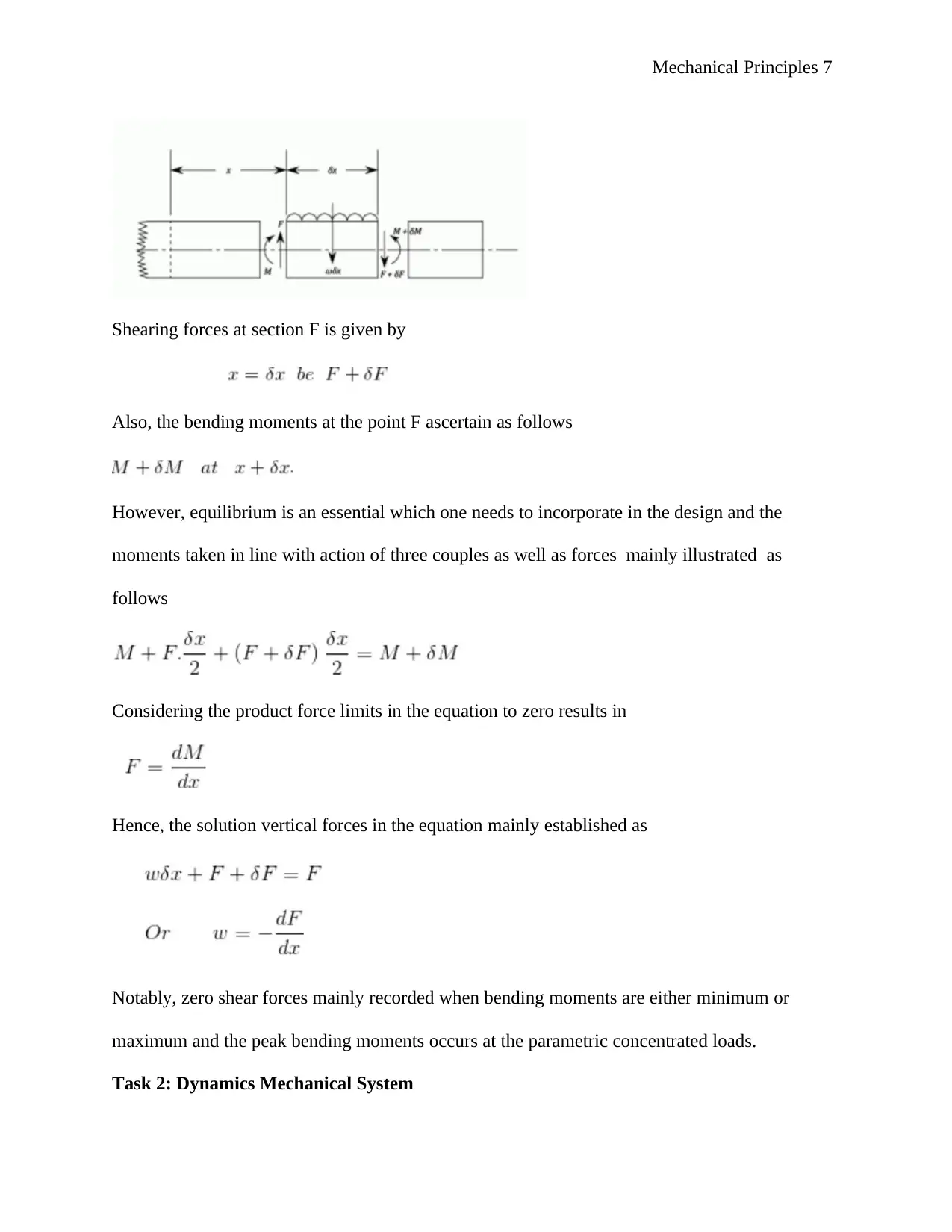
The analysis for the elements mainly illustrated and computed as follows using the diagram
below
⊘ This is a preview!⊘
Do you want full access?
Subscribe today to unlock all pages.

Trusted by 1+ million students worldwide
Mechanical Principles 7
Shearing forces at section F is given by
Also, the bending moments at the point F ascertain as follows
However, equilibrium is an essential which one needs to incorporate in the design and the
moments taken in line with action of three couples as well as forces mainly illustrated as
follows
Considering the product force limits in the equation to zero results in
Hence, the solution vertical forces in the equation mainly established as
Notably, zero shear forces mainly recorded when bending moments are either minimum or
maximum and the peak bending moments occurs at the parametric concentrated loads.
Task 2: Dynamics Mechanical System
Paraphrase This Document
Need a fresh take? Get an instant paraphrase of this document with our AI Paraphraser
Mechanical Principles 8
Explain the effects of energy transfer in mechanical systems with uniform acceleration
present
Preferably, mechanical energy transfers in the system are an essential norm and phenomena
which one need to consider at all times. Also, the uniform acceleration associated with it must be
included in the process as well.
Identify the magnitude and effect of gyroscopic reaction torque. Construct diagrams of the
vector solutions of velocity and acceleration
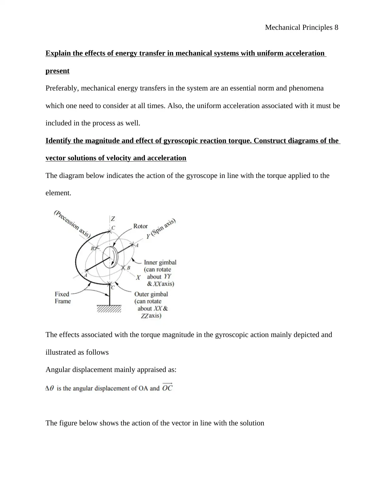
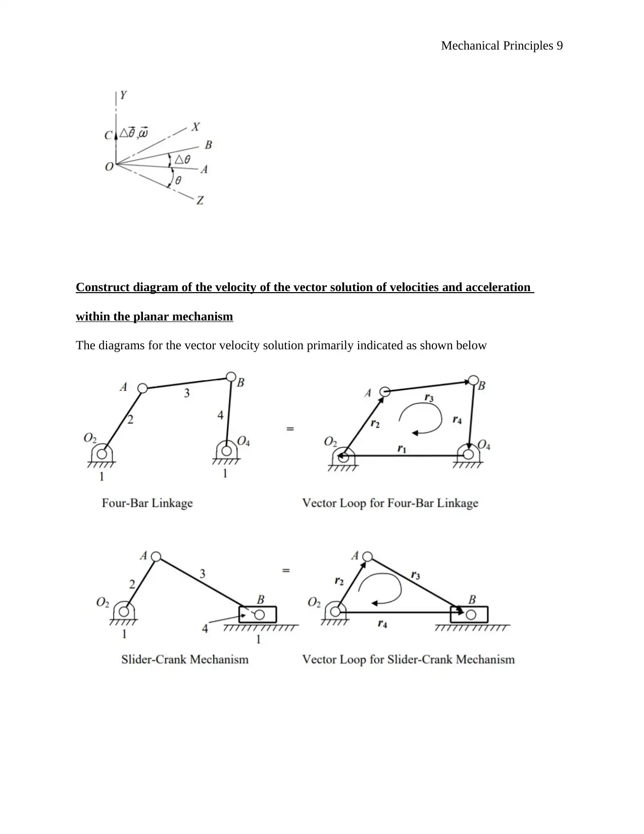
The diagram below indicates the action of the gyroscope in line with the torque applied to the
element.
The effects associated with the torque magnitude in the gyroscopic action mainly depicted and
illustrated as follows
Angular displacement mainly appraised as:
The figure below shows the action of the vector in line with the solution
Mechanical Principles 9
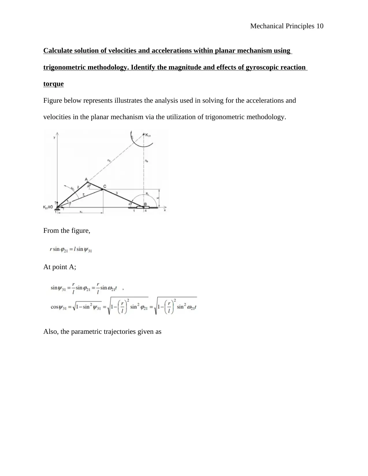
Construct diagram of the velocity of the vector solution of velocities and acceleration
within the planar mechanism
The diagrams for the vector velocity solution primarily indicated as shown below
Construct diagram of the velocity of the vector solution of velocities and acceleration
within the planar mechanism
The diagrams for the vector velocity solution primarily indicated as shown below
⊘ This is a preview!⊘
Do you want full access?
Subscribe today to unlock all pages.

Trusted by 1+ million students worldwide
Mechanical Principles 10
Calculate solution of velocities and accelerations within planar mechanism using
trigonometric methodology. Identify the magnitude and effects of gyroscopic reaction
torque
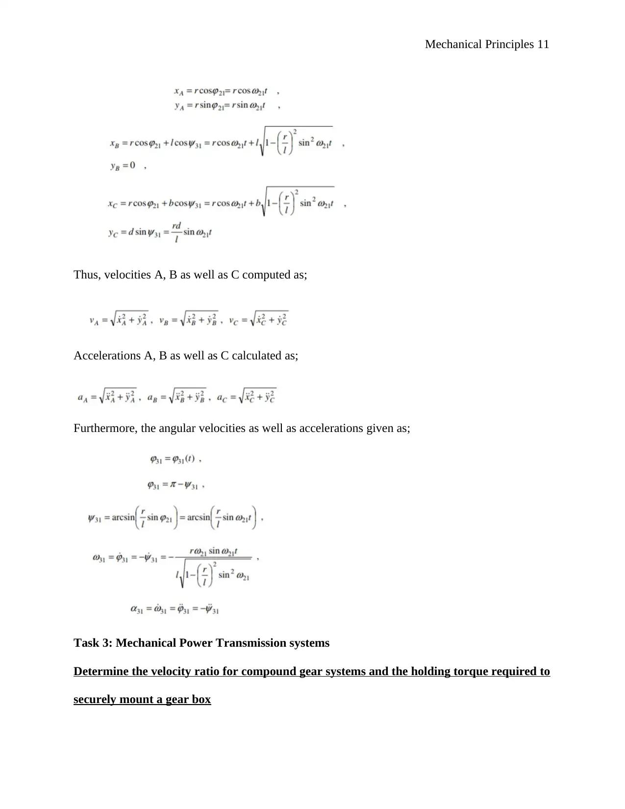
Figure below represents illustrates the analysis used in solving for the accelerations and
velocities in the planar mechanism via the utilization of trigonometric methodology.
From the figure,
At point A;
Also, the parametric trajectories given as
Paraphrase This Document
Need a fresh take? Get an instant paraphrase of this document with our AI Paraphraser
Mechanical Principles 11
Thus, velocities A, B as well as C computed as;
Accelerations A, B as well as C calculated as;
Furthermore, the angular velocities as well as accelerations given as;
Task 3: Mechanical Power Transmission systems
Determine the velocity ratio for compound gear systems and the holding torque required to
securely mount a gear box
Mechanical Principles 12
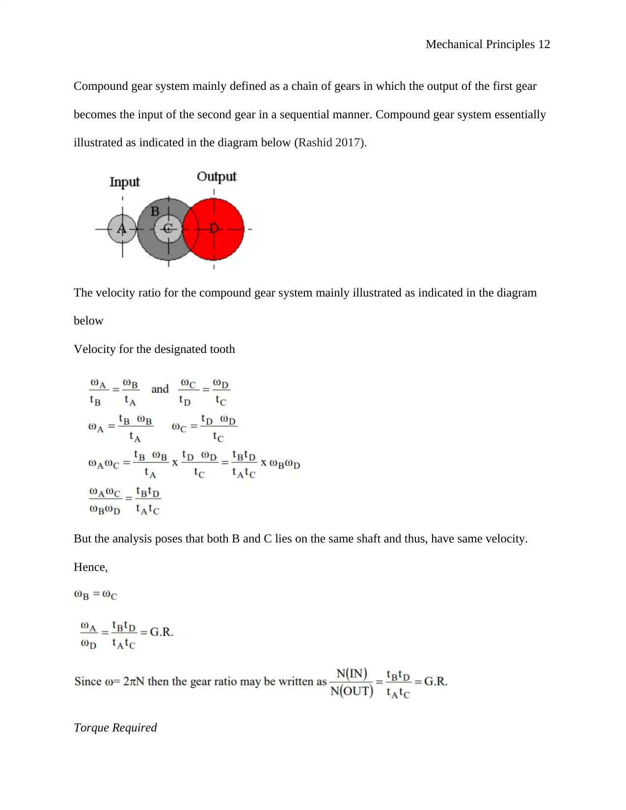
Compound gear system mainly defined as a chain of gears in which the output of the first gear
becomes the input of the second gear in a sequential manner. Compound gear system essentially
illustrated as indicated in the diagram below (Rashid 2017).
The velocity ratio for the compound gear system mainly illustrated as indicated in the diagram
below
Velocity for the designated tooth
But the analysis poses that both B and C lies on the same shaft and thus, have same velocity.
Hence,
Torque Required
⊘ This is a preview!⊘
Do you want full access?
Subscribe today to unlock all pages.

Trusted by 1+ million students worldwide
1 out of 19
Related Documents
Your All-in-One AI-Powered Toolkit for Academic Success.
+13062052269
info@desklib.com
Available 24*7 on WhatsApp / Email
![[object Object]](/_next/static/media/star-bottom.7253800d.svg)
Unlock your academic potential
Copyright © 2020–2026 A2Z Services. All Rights Reserved. Developed and managed by ZUCOL.


