Mechanical Engineering: Turbine Engine Design and Construction

Verified

Added on  2019/11/14

|2
|676
|309
Report
AI Summary
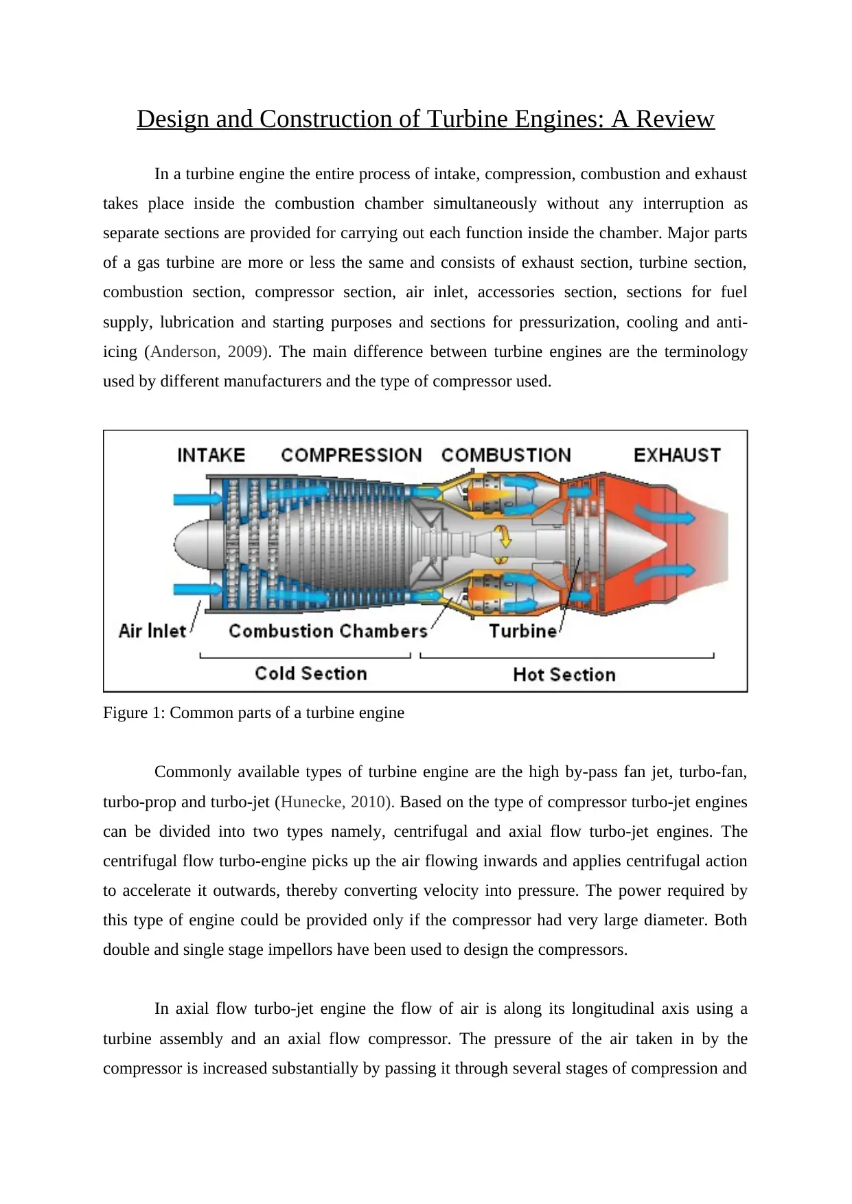
This report provides a comprehensive overview of turbine engine design and construction, covering various aspects of the process. It begins by outlining the fundamental components of a turbine engine, including the combustion chamber, compressor, and turbine sections. The report then differentiates between various types of turbine engines, such as high by-pass fan jet, turbo-fan, turbo-prop, and turbo-jet engines, emphasizing the differences in their designs and functionalities. A detailed analysis of centrifugal and axial flow turbo-jet engines is presented, highlighting the operational principles of each type of compressor. The report further explores the differences between turboprop and turbojet engines, including the use of coaxial shafts and gear reduction assemblies in turboprop designs. Finally, it discusses the design of turbofan engines, including the placement of the fan and the resulting fuel efficiency improvements. References to relevant research papers and textbooks are included.
Document Page
Design and Construction of Turbine Engines: A Review
In a turbine engine the entire process of intake, compression, combustion and exhaust
takes place inside the combustion chamber simultaneously without any interruption as
separate sections are provided for carrying out each function inside the chamber. Major parts
of a gas turbine are more or less the same and consists of exhaust section, turbine section,
combustion section, compressor section, air inlet, accessories section, sections for fuel
supply, lubrication and starting purposes and sections for pressurization, cooling and anti-
icing (Anderson, 2009). The main difference between turbine engines are the terminology
used by different manufacturers and the type of compressor used.
Figure 1: Common parts of a turbine engine
Commonly available types of turbine engine are the high by-pass fan jet, turbo-fan,
turbo-prop and turbo-jet (Hunecke, 2010). Based on the type of compressor turbo-jet engines
can be divided into two types namely, centrifugal and axial flow turbo-jet engines. The
centrifugal flow turbo-engine picks up the air flowing inwards and applies centrifugal action
to accelerate it outwards, thereby converting velocity into pressure. The power required by
this type of engine could be provided only if the compressor had very large diameter. Both
double and single stage impellors have been used to design the compressors.
In axial flow turbo-jet engine the flow of air is along its longitudinal axis using a
turbine assembly and an axial flow compressor. The pressure of the air taken in by the
compressor is increased substantially by passing it through several stages of compression and
tabler-icon-diamond-filled.svg

Paraphrase This Document

Need a fresh take? Get an instant paraphrase of this document with our AI Paraphraser
Document Page
then passed into the combustion chamber. The compressed air is then mixed with the fuel and
ignited which raises the temperature. The by-products expand through the turbine and leave
the compressor, in-turn driving it. As the by-products leave the compressor the temperature
and pressure falls to reach ambient pressure, producing a high velocity jet as the gas flows
through the propelling nozzle.
The difference between turboprop and turbojet engines is that there are more stages in
turboprop engines and generates more forward power through the gear train and shaft in order
to drive the propeller. The exhaust gases which pass through the extra stages help the turbine
to provide extra power. Coaxial shafts are used in case of multiple rotor turbines so as to
drive the propeller and compressor independently. The turboprop configuration is available in
the gear reduction or gearbox assembly which is connected to the torque meter assembly so
as to transmit the torque.
If the propeller in a turboprop engine is replaced using a duct enclosed axial flow fan,
then it is a turbofan turbine (Kroes and Wild 2010). The fan is either mounted on a separate
set of blades or on the first stage of compressor blades. Whereas the blades are mounted aft of
the turbine wheel or forward of the compressor. This converts more fuel energy to pressure
and consequently saves more fuel and in order to provide more power for driving the fan an
extra stage has to be added in the turbine and the jet nozzle requires to have a larger area.
Forward fan engines use two different duct designs one ducted along the outer case of the
engine and the other ducted overboard. Thus the exhaust gases are either directly passed
without mixing with the air or are mixed with air and then discharged.
References
Anderson, K. (2009). Propulsion Plant Accident Investigation. Embry-Riddle Aeronautical
University.
Hunecke, K. (2010). Jet Engines: Fundamentals of Theory, Design and Operation.
Marlborough: The Crowood Press
Kroes, M.J. and Wild, T.W. (2010). Aircraft Powerplants (Aviation Technology Series). New
Delhi, new Delhi: McGraw-Hill Higher Education.
chevron_up_icon
1 out of 2
circle_padding
hide_on_mobile
zoom_out_icon
[object Object]