Mechanics of Machines Exam Solution - Comprehensive Question Answers
VerifiedAdded on 2023/06/08
|13
|1238
|391
Homework Assignment
AI Summary
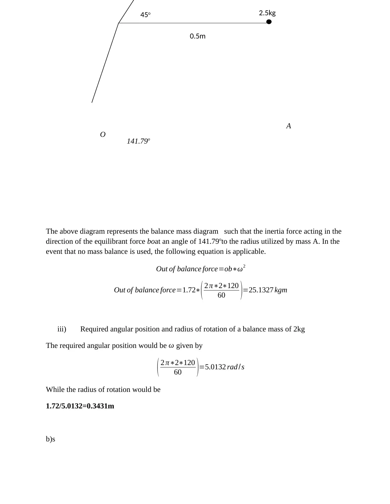
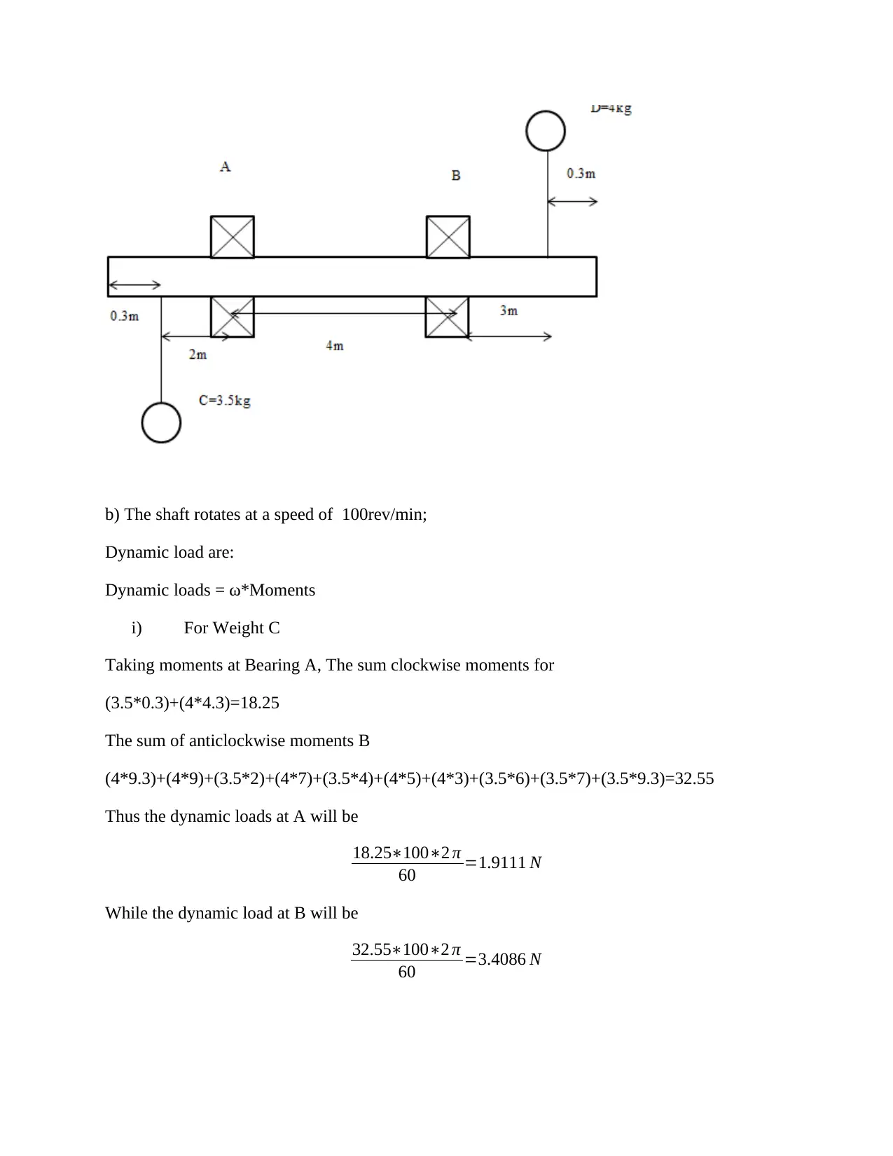
This document presents a comprehensive solution to a Mechanics of Machines exam, addressing a range of problems in mechanical engineering. The solution includes detailed step-by-step calculations and explanations for each question. The exam covers topics such as static and dynamic equilibrium, simple harmonic motion, velocity and angular velocity calculations in engine mechanisms, balancing of rotating masses, and analysis of forces and motion in a truck system. The solutions demonstrate the application of fundamental principles and formulas to solve complex engineering problems, making it a valuable resource for students studying mechanical engineering and preparing for similar exams. The document provides clear diagrams, formulas, and calculations to aid understanding and learning. The problems cover concepts such as friction, moments, amplitude and periodic time, and the analysis of dynamic loads. The solutions offer insights into the application of these concepts in practical scenarios.

`
Mechanics of Machines Exam
Name
Institution
Mechanics of Machines Exam
Name
Institution
Paraphrase This Document
Need a fresh take? Get an instant paraphrase of this document with our AI Paraphraser

Mechanics of Machines Exam
Question 1
When the crate is about to slide up the plane, the frictional force will act down the plane. F=0.3N
The equilibrium equations of the crate when it is about to slide or topple can be utilized to
identify the frictional force acting against the plane as well as the force applied to the crate.
F parallel= 2.5kN sin 20o= 2.2824kN
The reaction of the push is then computed
F vertical +Psin 15
Coefficient of friction (μs)= 0.3
The vertical forces are:
2.5sin 20= 2.2824kN
P cos 15 and
The frictional force that acts down the plane
The horizontal forces are
P
20o
1.5m
0.75m
15o
mg= 2.5kN
F
N

2.5 cos 20= 1.0202
P sin 15
N
The sum of forces in the above free body diagram should add up to zero when the crate is just
about to topple or slide. That is:
∑ F acting downthe plane=Pcos 15−F−2.5 sin 20=0
∑ F acting up the plane=Psin 15+ N −2.5 cos 20=0
F=0.3 N
Thus
Pcos 15−0.3 N −2.5 sin 20=0
Psin15+N −2.5 cos 20=0
−0.7597 P−0.3 N =2.2824
0.6503 P+ N=1.0202
P=-4.5847kN
N= 4.4603kN
F= 0.3N= 1.3381kN
Thus the crate first will topple due to the value being smaller than the frictional force. It would
slide if the frictional force were slightly smaller than the applied force.
The minimum force required to cause sliding or toppling is 4.5847kN.
Question 2
The simple harmonic motion computation is
Velocity1=3m/s when Displacement1= 120mm from midpointand;
Velocity2 = 1.0m/s when Displacement2 = 200mm from midpoint
i) Amplitude of motion
Let ω=angular velocity and
.r=amplitude
⊘ This is a preview!⊘
Do you want full access?
Subscribe today to unlock all pages.

Trusted by 1+ million students worldwide

We know that:
V =ω √ r2−x2
3 m/s=ω √ r2 −0.122 1
Similarly
1.0 m/ s=ω √r2 −0.122 2
Dividing equation 1 by equation 2
3
1 = ω √ r2−0.122
ω √ r2−0.22
9
1 = r2−0.122
r2−0.22
9 r2−0.36=r 2−0.0144
8 r2=0.3456
R=0.2078m
The amplitude of motion is thus 207.8mm
ii) Periodic time
tp= 2 π
ω
ω can be obtained by substituting r above in the equation ie
3 m/s=ω √ 0.20782 −0.122
ω=17.68 rad /s
Thus;
tp= 2 π
17.68
tp=0.3554 s
b) A helical spring
k=12kN/m
m=15kg
Paraphrase This Document
Need a fresh take? Get an instant paraphrase of this document with our AI Paraphraser

a=14mm
i) Periodic time
Tp=2 π √ m
s
Tp=2 π √ 15
12∗103
Tp=0.2221 s
ii) The maximum acceleration
Ma=sx
A= sx
m
A=12000∗0.014
15
A=11.2rad /s2
iii) The velocity
V =ω √r2−x2
And
ω= √ g
δ
And δ= mg
s =15∗9.81
12000 =0.01226 m
Thus
ω= √ 9.81
0.01226
ω=28.2872 rad /s
V =28.2872∗0.0142
V =0.005 m/ s
i) Periodic time
Tp=2 π √ m
s
Tp=2 π √ 15
12∗103
Tp=0.2221 s
ii) The maximum acceleration
Ma=sx
A= sx
m
A=12000∗0.014
15
A=11.2rad /s2
iii) The velocity
V =ω √r2−x2
And
ω= √ g
δ
And δ= mg
s =15∗9.81
12000 =0.01226 m
Thus
ω= √ 9.81
0.01226
ω=28.2872 rad /s
V =28.2872∗0.0142
V =0.005 m/ s

Question 3
The engine mechanism is as follows
If crank speed is 144rev/min,
i) VelocityB?
V =ωr
For the crank speed is given by
144∗2 π
60 =ω
ω=15.08 rad /s
Substituting
V =15.08∗0.6
V =15.08∗0.6
V =9.0478 m/s
B
65o
O
A
C
0.6m 0.15m
The engine mechanism is as follows
If crank speed is 144rev/min,
i) VelocityB?
V =ωr
For the crank speed is given by
144∗2 π
60 =ω
ω=15.08 rad /s
Substituting
V =15.08∗0.6
V =15.08∗0.6
V =9.0478 m/s
B
65o
O
A
C
0.6m 0.15m
⊘ This is a preview!⊘
Do you want full access?
Subscribe today to unlock all pages.

Trusted by 1+ million students worldwide

ii) Angular velocity of connecting rod
V n=v sinθ
V n=9.0478 sin65
V n=7.4810
And V n=ωr
Thus
7.4810=ω 0.6
ω=12.4683 rad /s
iii) Velocity at C
V =ω √ r2−x2
V =12.4683 √ 0.62 −0.182
V =7.1364 m/s
Question 4
a)
B
A
If the rotating speed of the shaft is 80rev/min;
i) Out of balance force on the shaft bearing?
RA= 0.6m
RB= 0.5m
The condition for equal inertia forces is shown below:
0.6m
0.5kg
2.5kg45o
0.5m
Paraphrase This Document
Need a fresh take? Get an instant paraphrase of this document with our AI Paraphraser

m1 r 1=m2 r2
Thus the mr value for A is
2.5*0.5=1.25kg-m
While for b is
0.6*0.5=0.3kg-m
The values are represented by the following diagram that represents the force polygon
From the scale diagram above the mr value of ob is foun to be 1.72kg-m.
The equilibrant obtained was also taken to be opposite and equal to the out of balance force.
Given the mr value for the balance mass is given as 1*r kg-m, the r value for this specific case
was found as
1*r=1.72kg-m
Thus r=1.72kgm. This represents the radius of the rotation of the balance mass.
This value must thus be positioned to allow the force of inertia to act in the direction bo. This is
demonstrated in the figure below
o
b
a
0.6m
0.5kg
B

The above diagram represents the balance mass diagram such that the inertia force acting in the
direction of the equilibrant force boat an angle of 141.79oto the radius utilized by mass A. In the
event that no mass balance is used, the following equation is applicable.
Out of balance force=ob∗ω2
Out of balance force=1.72∗( 2 π∗2∗120
60 )=25.1327 kgm
iii) Required angular position and radius of rotation of a balance mass of 2kg
The required angular position would be ω given by
( 2 π∗2∗120
60 )=5.0132 rad / s
While the radius of rotation would be
1.72/5.0132=0.3431m
b)s
2.5kg45o
0.5m
A
O 141.79o
⊘ This is a preview!⊘
Do you want full access?
Subscribe today to unlock all pages.

Trusted by 1+ million students worldwide

b) The shaft rotates at a speed of 100rev/min;
Dynamic load are:
Dynamic loads = ω*Moments
i) For Weight C
Taking moments at Bearing A, The sum clockwise moments for
(3.5*0.3)+(4*4.3)=18.25
The sum of anticlockwise moments B
(4*9.3)+(4*9)+(3.5*2)+(4*7)+(3.5*4)+(4*5)+(4*3)+(3.5*6)+(3.5*7)+(3.5*9.3)=32.55
Thus the dynamic loads at A will be
18.25∗100∗2 π
60 =1.9111 N
While the dynamic load at B will be
32.55∗100∗2 π
60 =3.4086 N
Paraphrase This Document
Need a fresh take? Get an instant paraphrase of this document with our AI Paraphraser

Question 5:
Weight of truck=10tons
Weight of car=2.5tons
Slope = 1o
Tractive resistance = 300N/Ton
Engine torque= 450Nm
Engine speed =2600rev/min
Gear reduction from axle to engine=8:1
Wheel diameter 800mm
i) Linear maximum speed of the truck
v=ωr
The angular velocity of the engine can be computed as
ω= 2600∗2 π
60 =272.2714 rad / s
Given the gear reduction from axle to engine=8:1
The radius used by the engine can be taken from considering the gear reduction axle such that
the diameter is
800/8=100mm.
The radius thus is 50mm.
v=272.2714 rad
s ∗0.05 m
v=272.2714 rad
s ∗0.05 m=13.64 m/ s
ii) Acceleration of the truck
a=αr
The angular acceleration can be established by considering the formula to compute torque in
angular motion,
T =Iα
450=Iα

The moment of inertia can be computed using the formula,
I =m r2
Where m is the mass of the truck and r is the radius of the wheels of the truck
I =10000 ¿ 0.42
I =1600 m4
Substituting
450=1600∗α
α=0.28125 rad / s2
Thus the acceleration of the truck
a=0.28125∗0.4
a=0.01125 m/s2
iii) Tension of tow tape
T −Tractive forc es=mcar a
T −300 N /tonne of total mass pulled=mcar a
Total mass of cars=10+2.5=12.5tons
Tractive forces=300∗12.5=3750 N
Substituting
T −3750=2500∗0.01125
⊘ This is a preview!⊘
Do you want full access?
Subscribe today to unlock all pages.

Trusted by 1+ million students worldwide
1 out of 13
Related Documents

Your All-in-One AI-Powered Toolkit for Academic Success.
+13062052269
info@desklib.com
Available 24*7 on WhatsApp / Email
Unlock your academic potential
Copyright © 2020–2025 A2Z Services. All Rights Reserved. Developed and managed by ZUCOL.