Mechatronic Design E-Bike Project: Western Sydney University, SCC
VerifiedAdded on 2023/06/11
|53
|6959
|73
Project
AI Summary
This project report outlines the design and development of an e-bike intended for use within Western Sydney University's Penrith campus as part of a smart campus initiative. The project aims to provide a sustainable, efficient, and theft-proof mode of transportation for students. The design process encompasses mechatronic design principles, including conceptual designs, performance criteria, and design for X (DFX) considerations such as manufacturing, assembly, and environmental impact. Material selection focuses on titanium alloys due to their strength and lightweight properties. The report details the manufacturing processes for the frame, handlebars, and forks, as well as the integration of components like the hub motor, battery, and generator. Safety considerations, force and stress analyses, and a mode of failure analysis are also included. The final design incorporates a frame made of titanium, along with considerations for ergonomics and user safety. The project concludes with recommendations for further work and acknowledges contributions to the design process. Desklib provides access to this and other solved assignments for students.
Mechanical Design 1
MECHATRONIC DESIGN
By Name
Course
Instructor
Institution
Location
Date
MECHATRONIC DESIGN
By Name
Course
Instructor
Institution
Location
Date
Paraphrase This Document
Need a fresh take? Get an instant paraphrase of this document with our AI Paraphraser
Mechanical Design 2
Executive Summary
The aims and objectives of the project design are outlined and explained within this report. In
addition, the criteria of performance is too discussed in a manner which the standards of
design that are supposed to be achieved, development requirements and the disadvantages of
the design are well elaborated. During the methodology of design, the process of mechatronic
design is underwent which entails the consistent and outlined regular E-bike devising process
that undergoes numerous conceptual designs to approve whether they achieve the standards
of design. X (DFX) design is a process or technique in which an assessment of the assembly
design, manufacturing design, analysis effects, mode of failures and the environmental design
which all satisfies the criteria of quality.
Mechanical Design 3
Table of content
Contents
Executive Summary...............................................................................................................................2
Table of content....................................................................................................................................3
Introduction and background.................................................................................................................5
Aim and objective.................................................................................................................................6
Performance Criteria and Design Constraints........................................................................................7
Specifications of design.....................................................................................................................7
Basic Design Decisions.........................................................................................................................8
Design Analysis.....................................................................................................................................8
Design for X (DFX)...........................................................................................................................8
Design for manufacturing..............................................................................................................8
Products Manufacturing...................................................................................................................11
Mechanical disc brake.....................................................................................................................15
Contrast...........................................................................................................................................15
A system of chain driven.............................................................................................................15
Belt driven system:......................................................................................................................15
Electrical motor (hub motor)...........................................................................................................17
Assembly manufacturing costs:...........................................................................................................19
Design for Environment (DFE)...........................................................................................................19
Life cycle assessment..........................................................................................................................20
Environmental impact.........................................................................................................................21
Safety design.......................................................................................................................................23
Road rules:.......................................................................................................................................23
Safety equipment:............................................................................................................................23
University of western Sydney..........................................................................................................24
Rack system of the bike:......................................................................................................................24
Design Analysis....................................................................................................................................25
Force analysis..................................................................................................................................25
Stress analysis..................................................................................................................................25
Motion analysis...............................................................................................................................27
Final Design........................................................................................................................................28
Frame – handlebars..........................................................................................................................28
Forks or frame.................................................................................................................................28
Attaching wheels, tires and hubs.....................................................................................................28
Frame-wheel....................................................................................................................................28
⊘ This is a preview!⊘
Do you want full access?
Subscribe today to unlock all pages.
Trusted by 1+ million students worldwide
Mechanical Design 4
brakes..............................................................................................................................................29
Frame-saddle, e-bike seat................................................................................................................29
Internal-frames................................................................................................................................29
Results.................................................................................................................................................29
Analysis for the finite elements...........................................................................................................29
Mode of failure and analysis effects....................................................................................................30
Discussion...........................................................................................................................................31
Benefits............................................................................................................................................31
Disadvantages..................................................................................................................................31
Recommendations/further work..........................................................................................................31
Acknowledgments...............................................................................................................................32
3D design files.....................................................................................................................................33
For the whole bike...............................................................................................................................36
Conclusion...........................................................................................................................................36
Bibliography........................................................................................................................................38
Appendices..........................................................................................................................................39
Appendix A – Existing E-bike.........................................................................................................39
Appendix B – Concept Designs.......................................................................................................41
Appendix C – Final Design Drawings/Model..................................................................................42
Appendix D – Bill of Materials.......................................................................................................46
Appendix E – The Addition Add-ons (Bought Items).....................................................................48
Appendix F – DFX..........................................................................................................................50
Paraphrase This Document
Need a fresh take? Get an instant paraphrase of this document with our AI Paraphraser
Mechanical Design 5
Introduction and background
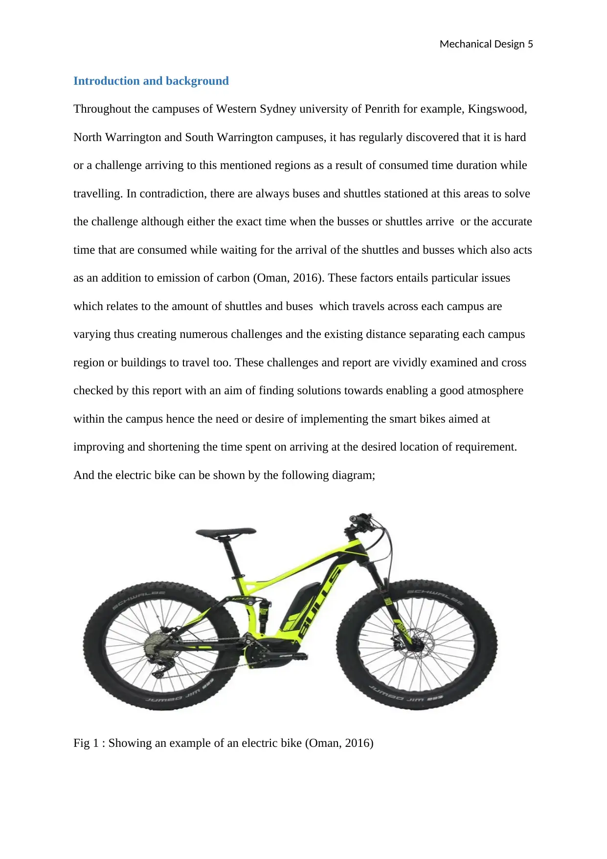
Throughout the campuses of Western Sydney university of Penrith for example, Kingswood,
North Warrington and South Warrington campuses, it has regularly discovered that it is hard
or a challenge arriving to this mentioned regions as a result of consumed time duration while
travelling. In contradiction, there are always buses and shuttles stationed at this areas to solve
the challenge although either the exact time when the busses or shuttles arrive or the accurate
time that are consumed while waiting for the arrival of the shuttles and busses which also acts
as an addition to emission of carbon (Oman, 2016). These factors entails particular issues
which relates to the amount of shuttles and buses which travels across each campus are
varying thus creating numerous challenges and the existing distance separating each campus
region or buildings to travel too. These challenges and report are vividly examined and cross
checked by this report with an aim of finding solutions towards enabling a good atmosphere
within the campus hence the need or desire of implementing the smart bikes aimed at
improving and shortening the time spent on arriving at the desired location of requirement.
And the electric bike can be shown by the following diagram;
Fig 1 : Showing an example of an electric bike (Oman, 2016)
Introduction and background
Throughout the campuses of Western Sydney university of Penrith for example, Kingswood,
North Warrington and South Warrington campuses, it has regularly discovered that it is hard
or a challenge arriving to this mentioned regions as a result of consumed time duration while
travelling. In contradiction, there are always buses and shuttles stationed at this areas to solve
the challenge although either the exact time when the busses or shuttles arrive or the accurate
time that are consumed while waiting for the arrival of the shuttles and busses which also acts
as an addition to emission of carbon (Oman, 2016). These factors entails particular issues
which relates to the amount of shuttles and buses which travels across each campus are
varying thus creating numerous challenges and the existing distance separating each campus
region or buildings to travel too. These challenges and report are vividly examined and cross
checked by this report with an aim of finding solutions towards enabling a good atmosphere
within the campus hence the need or desire of implementing the smart bikes aimed at
improving and shortening the time spent on arriving at the desired location of requirement.
And the electric bike can be shown by the following diagram;
Fig 1 : Showing an example of an electric bike (Oman, 2016)
Mechanical Design 6
Aim and objective
This project mandated a main goal of developing and designing an e-bike possessing the
below listed aspect:
Friendliness to the neighbouring environment
Possession of aesthetically pleasing design
Design attaining sustainability
A functional efficiency
Proof to theft
Usability safety
The smart bicycle is to be designed and introduced to the community of Penrith University to
be adopted by the university students to freely travel within the institution while achieving
sustainability for the rest of the public or students within the institution. The key goal of the
entire system is coming up with a bike that avails a smart campus whereby the travelling time
duration between and across campuses and lectures around or within Kingwood, north and
south Warrington is greatly reduced to a negligible duration. It is a capability finding the
originality of locations which normally consumes time to reach while walking as an
opposition, and only deserves a couple of few minutes to reach or arrive on a smart bicycle.
Another significant target of the smart bicycle is the functionality, environment protection
and e-bike costing.
⊘ This is a preview!⊘
Do you want full access?
Subscribe today to unlock all pages.
Trusted by 1+ million students worldwide
Mechanical Design 7
Performance Criteria and Design Constraints
Specifications of design
There existed an intension of creating or coming up with a bike that would be utilized by a
variety of students hence the need of looking for a single design that would fit all students.
Since sizing of the bike was very significant, it became the initial step of approach hence
forming a beginning idea or concept. In relation to the design, it was a key consideration that
the chosen design met the standards best suiting all students.
Allowing easy transportation of students from or between UWS campus of Penrith since
students had to travel the distance between various campuses in order to attend lectures was
the main intention to be achieved by the bike. However, majority of the students currently
border busses and cars to reach their destinations between campuses as the travelling means
between the campuses despite this idea being not practical as it results to environmental
pollution thus coming up with an e-bike would easily facilitate travelling of the students
between the campuses cheap, faster and more friendly to the environment. Coming up with a
pedal assist bike is the main function or intention in addition to creativities such as generators
that would provide power freely as result of the pealing by the student directed to the user’s
smart phone and or light for the bike.
The bike would have to meet the goal of complying with the above listed requirements of
design as a criteria for evaluation and in addition, the degree of achieving the requirements of
design will be assessed, the most fitting design requirement and too taking a consideration to
the suitability of the most complex design of manufacture.
Paraphrase This Document
Need a fresh take? Get an instant paraphrase of this document with our AI Paraphraser
Mechanical Design 8
Basic Design Decisions
Towards the end concept of Appendix B, figure 9 was settled on as a portion of the main idea
was having very minimal materials as the system of damping would complicate the process
of manufacturing since the support of the seat frame would need a compulsory system of
pivoting attached to the main frame of the bike. It simultaneously resulted to a consideration
to the frame force analysis leading to the choice of material being very significant. This will
be elaborated further within the report.
Design Analysis
The concepts 1 and 2 as shown in the figures 8 and 9 of the Appendix B chooses putting all
the components in a frame making the bike to look aesthetic acts as a protection of the bike
from weathering. These mentioned components entails system of the belt drive, generator and
battery, hub of the motor and all-inclusive wiring system.
Design for X (DFX)
Design for manufacturing
Design for manufacturing commonly known as DFM is a practice for development of the
entire process of manufacturing across the development of the product. Majority of the e-bike
parts that are single are usually effective in relation to cost since there exist numerous parts or
components that are accompanied to the bicycle which includes both expensive materials and
parts that have to undergo manufacturing process. All these brought together results into a
generally expensive bicycle being sold. DFM forms a general solution to the desired
processes of manufacturing in such a manner that the whole process is made simple. The
main concept in this is to generally reduce the value or the costing of the product and the
material quality as well.
Mechanical Design 9
Materials
During the primary and manufacturing production process and level of production of
products, materials or substance utilized are usually known as raw materials. They usually
compose of natural resources such as soil, wood and iron just to mention a few. These raw
materials are usually modified in order to be used in other related processes. They are at
times talked about as supplies which are generally purchased and sold over the whole world.
ITEM
NO.
PART COST ($) QTY.
1 Frame 550 1
2 handle bars 50 1
3 Hub-Motor 290 1
4 side plate cover 25 1
5 E-bike seat 170 1
6 pedal assembly 1
6.1 Arm 40 2
6.2 Tube 20 1
6.3 tube pedal 30 2
6.4 Pedals 200 2
7 Battery 20 1
8 front tire assembly 1
8.1 rim front 150 1
⊘ This is a preview!⊘
Do you want full access?
Subscribe today to unlock all pages.
Trusted by 1+ million students worldwide
Mechanical Design 10
8.2 Tire 38 1
9 wheel back 1
9.1 Rim 150 1
9.2 Tire 38 1
10 final bike generator 1
10.1 rubber wheel 10 1
10.2 generator shaft 20 1
10.3 bike light generator 15 1
10.4 motor for generator 60 1
Table 1: showing the cost of materials of electric bike.
Alloys of aluminium properties- very strong but light, great resistance to corrosion,
ability to recycling, friendliness to the environment and cost effective.
Alloys of titanium properties- good strength, relatively low density, good resistance
to corrosion and possession of light weight.
Steel alloys and its properties- better resistance to corrosion, strong or hard,
formability features, ductility, resistance to corrosion and less cost effective.
Fibre of carbon- possession of high strength to weight ratio, high electric
conductivity, and resistance to corrosion and relatively less cost effective.
Paraphrase This Document
Need a fresh take? Get an instant paraphrase of this document with our AI Paraphraser
Mechanical Design 11
Steel alloy and alloys of titanium were considered since the two materials were very
compatible throughout the project design. In addition to this, steel was the commonly used
material in the bike designing facility of the manufacturing process in comparison to
titanium. This material, steel, is very light, very cost effective, friendly and easy to be applied
in work, possess a low density, highly resistance to corrosion and possess high durability.
In the last moments of deciding on the materials to be used, both steel and titanium were
examined while testing their respective strengths via the process of PEA which categorically
settled on the titanium as the strongest and most viable of the two. Eventually, titanium was
utilized as the final material or product since it possessed the best strength or hardness in
addition to it having a light weight.
Products Manufacturing
Frame
The material that is selected, titanium is made smooth through heating then proceeded by
soaking in acids. Hollow pieces of the material are then made after which are measured and
cut into the desired measurement specifications. A process usually known as cold drawing is
then conducted which produces the said modified material into a shape applying a solid
material that is forced into the internal section via the hollow piece with an aim of making it
have a hollow circular shape. The materials are then passed through a butting process which
adjusts the thickness in the intended regions required.
The following step of process is the combination or joining together the material pieces that
are hollow forming a frame in a geometric shape. This mentioned process is accompanied
with gluing or welding which are adjusted when hot with an intention of getting the best
Mechanical Design 12
accuracy. On completion of this, the frame is exposed to painting via spraying or chroming
with an aim of preventing it from effects of corrosion and foe the last touch (Slinn, 2010).
The resultant frame that is being produced is thus a very unique element that encompasses of
extreme differing shapes and thickness which are required in order to avail the internal
appliances which includes generator and wiring with an intension of re-ensuring the desired
thickness quantity capable of conducting the said internal appliances. The diagram below
shows frame of electric bike
Fig 2 : Showing frame of electric bike (Slinn, 2010)
Handlebars and forks
This is a process similar to the one on frame. The material that is selected, titanium is made
smooth through heating then proceeded by soaking in acids. Hollow pieces of the material are
then made after which are measured and cut into the desired measurement specifications. A
process usually known as cold drawing is then conducted which produces the said modified
material into a shape applying a solid material that is forced into the internal section via the
⊘ This is a preview!⊘
Do you want full access?
Subscribe today to unlock all pages.
Trusted by 1+ million students worldwide
1 out of 53


Your All-in-One AI-Powered Toolkit for Academic Success.
+13062052269
info@desklib.com
Available 24*7 on WhatsApp / Email
![[object Object]](/_next/static/media/star-bottom.7253800d.svg)
Unlock your academic potential
Copyright © 2020–2026 A2Z Services. All Rights Reserved. Developed and managed by ZUCOL.