CPCCBC5018A: Medium Rise Structure Footing System Analysis Report

Verified

Added on  2022/10/01

|11
|1087
|25
Report
AI Summary
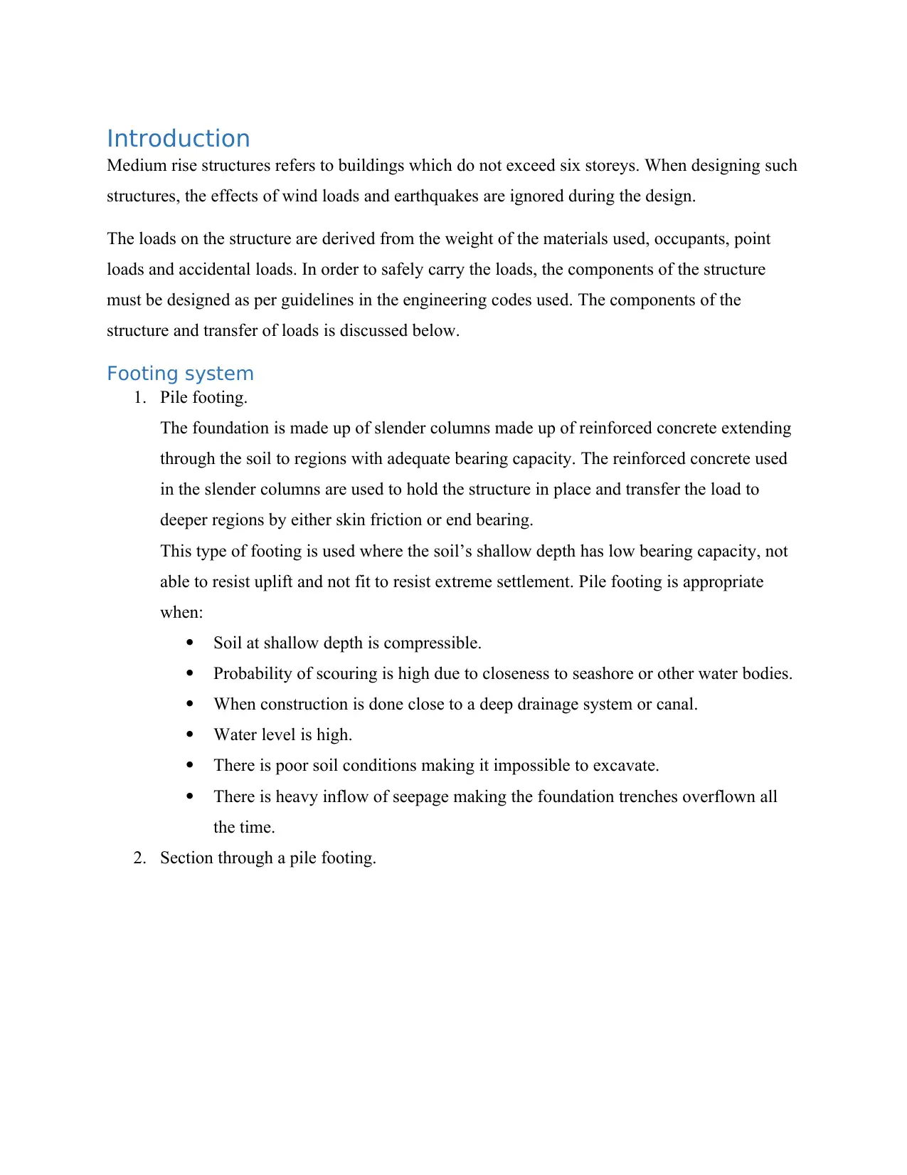
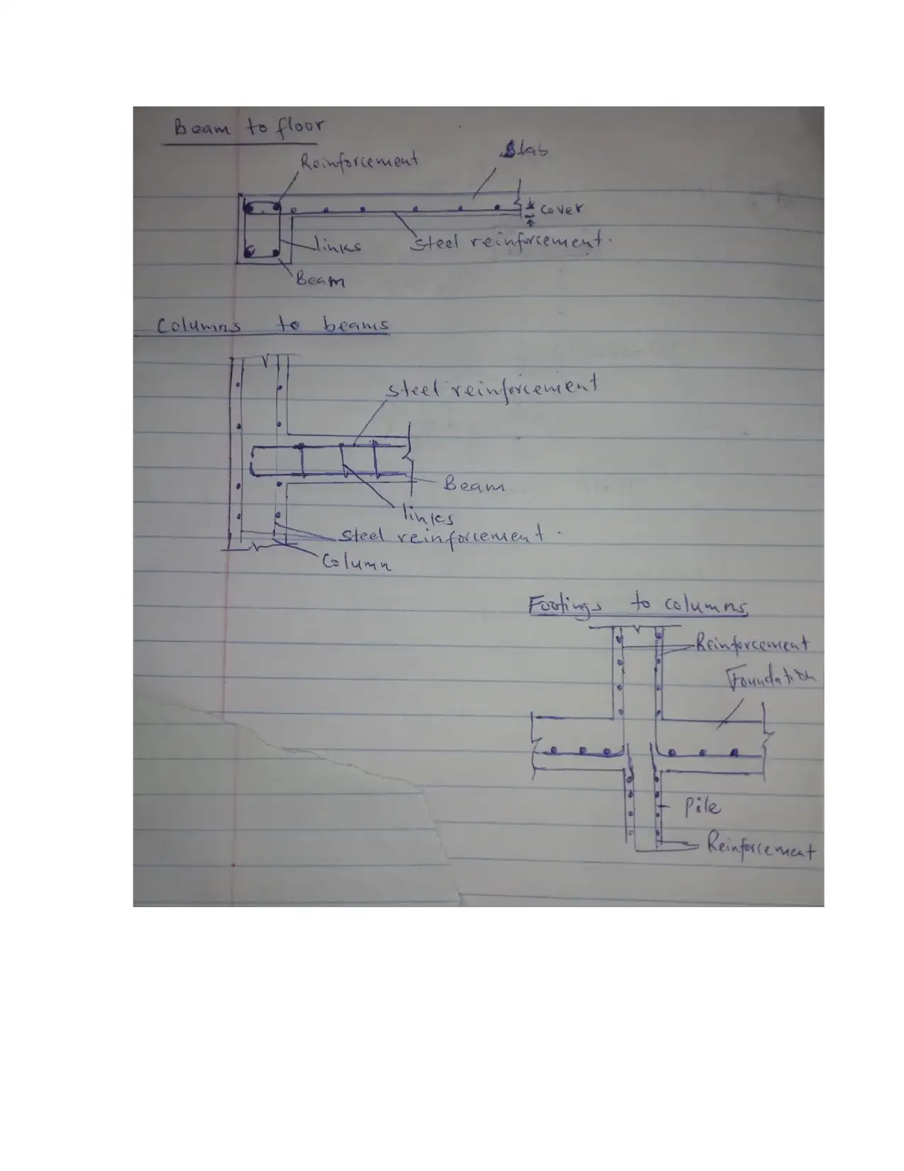
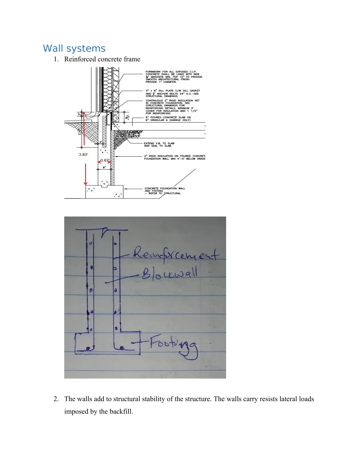
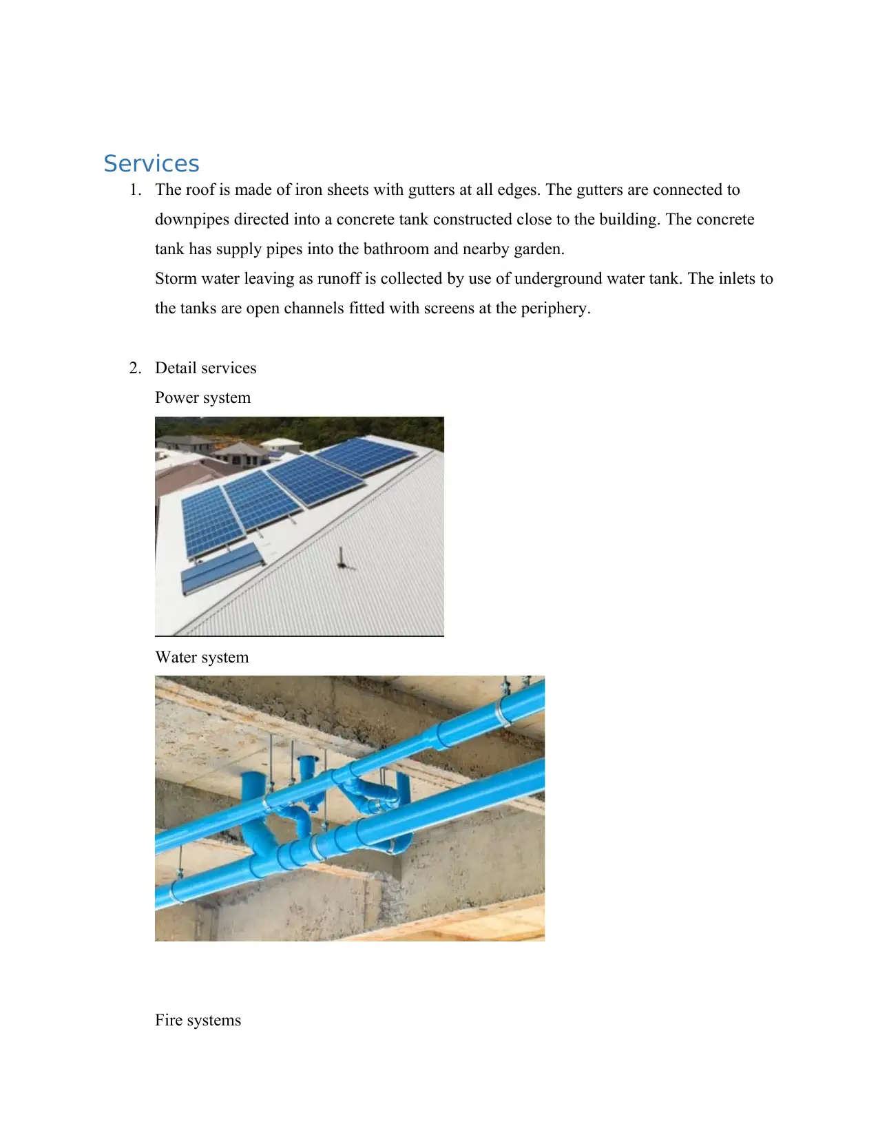
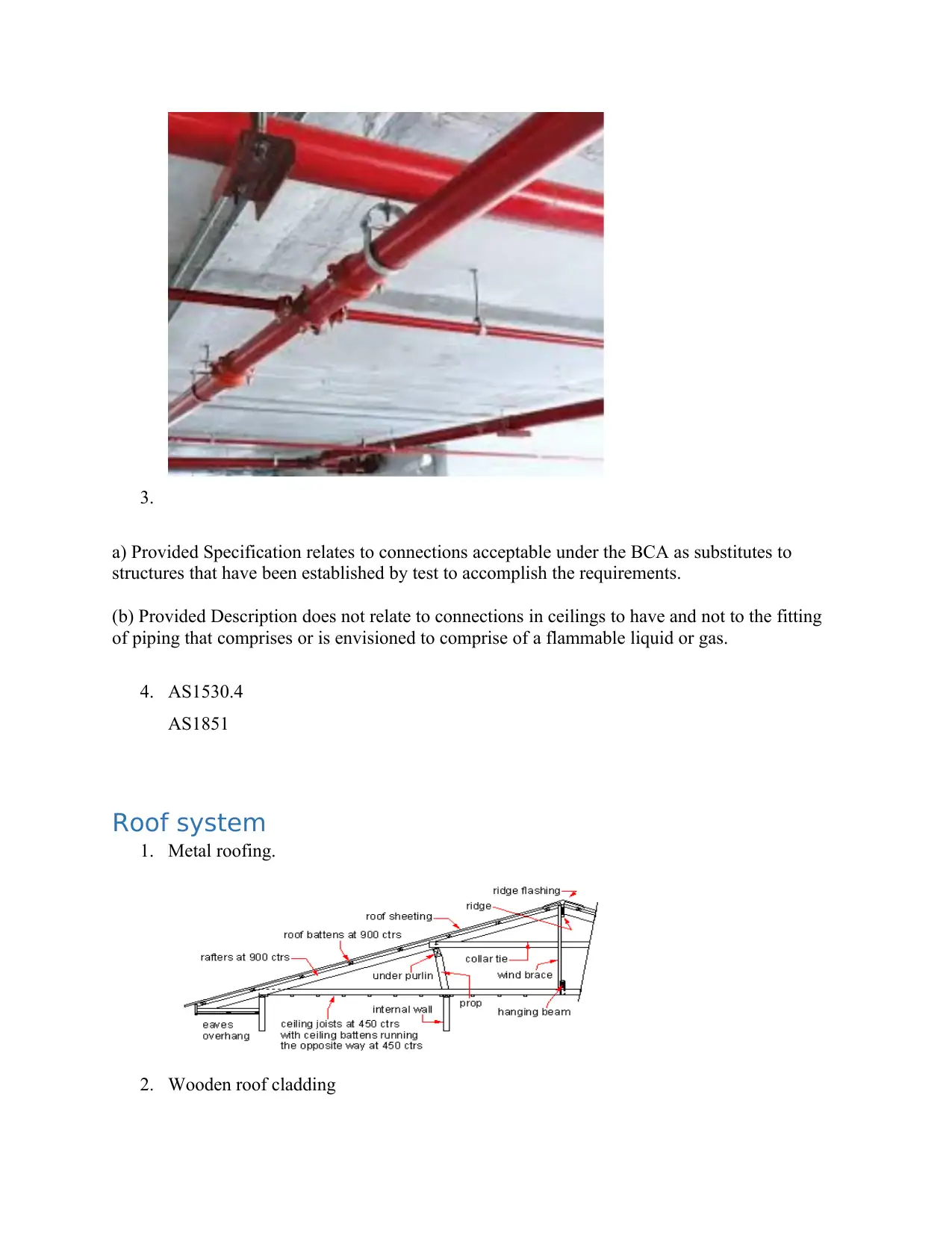
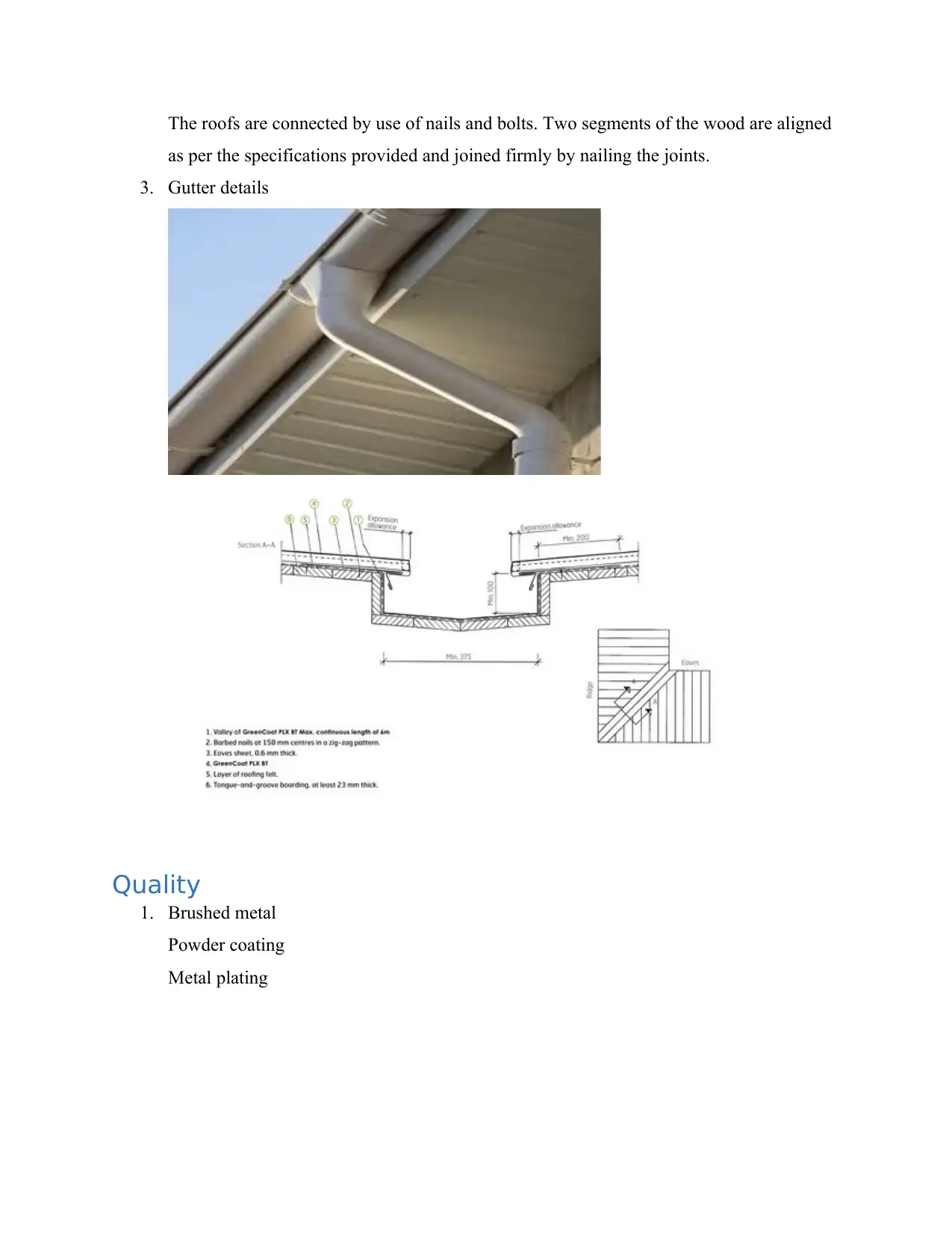
This report analyzes the footing systems used in medium rise structures, specifically focusing on buildings not exceeding six storeys. It details the design considerations, including the impact of loads from materials, occupants, and accidental factors, while disregarding wind and earthquake effects. The report explores the use of pile footings, describing their construction, suitability for different soil conditions, and load transfer mechanisms. It examines the structural system, including floor slabs, beams, columns, and footings, and explains how loads are distributed throughout the building. The report also discusses the connections between structural members, floor systems, construction sequences, wall systems, and service elements such as roofing, gutters, and water and power systems. References to relevant engineering codes and standards are also included.
Document Page
Introduction
Medium rise structures refers to buildings which do not exceed six storeys. When designing such
structures, the effects of wind loads and earthquakes are ignored during the design.
The loads on the structure are derived from the weight of the materials used, occupants, point
loads and accidental loads. In order to safely carry the loads, the components of the structure
must be designed as per guidelines in the engineering codes used. The components of the
structure and transfer of loads is discussed below.
Footing system
1. Pile footing.
The foundation is made up of slender columns made up of reinforced concrete extending
through the soil to regions with adequate bearing capacity. The reinforced concrete used
in the slender columns are used to hold the structure in place and transfer the load to
deeper regions by either skin friction or end bearing.
This type of footing is used where the soil’s shallow depth has low bearing capacity, not
able to resist uplift and not fit to resist extreme settlement. Pile footing is appropriate
when:
Soil at shallow depth is compressible.
Probability of scouring is high due to closeness to seashore or other water bodies.
When construction is done close to a deep drainage system or canal.
Water level is high.
There is poor soil conditions making it impossible to excavate.
There is heavy inflow of seepage making the foundation trenches overflown all
the time.
2. Section through a pile footing.
tabler-icon-diamond-filled.svg

Paraphrase This Document

Need a fresh take? Get an instant paraphrase of this document with our AI Paraphraser
Document Page
Figure 1: Section through a pile footing.
3. Section through retaining wall.
Document Page
Structural system
1. Diagram showing how a frame supports the load of the building.
A system responsible for carrying loads from one component of the structure to another
results to a continuous path throughout the structure. The system is as follows:
The floor slabs carry the loads imposed on the floor of each storey. The loads
include self-loads, surface loads, linear loads and point loads.
The beams carry loads transmitted to them by the slabs as well as their own
weight. They also carry loads of the walls installed on them.
The beam loads are carried by the column. The column transfers this loads to the
foundation.
Document Page
The loads from the columns are carried by footings (foundation). The footings
transfers the loads to the ground.
Figure 2: Load path from the slab of the structure to the bearing soil/rock.
2. Types of connections between structural members.
Beam to floors
Floors/slabs transfer the loads to beams. Therefore, slabs ensure that all the loads
imposed on it are safely transferred to the beams. The slabs also distribute loads across
them thus avoiding cumulating of stress at one point (Comodromos, 2009).
Columns to beams
Beams transfer loads to columns. The columns are placed at intervals large enough to
accommodate the accumulating loads in beams.
Footings to columns
Columns ensures that all the loads it carries are safely transferred to the foundation
(footing). The foundation then transfers the loads to the ground.
tabler-icon-diamond-filled.svg

Paraphrase This Document

Need a fresh take? Get an instant paraphrase of this document with our AI Paraphraser
Document Page
Document Page
Floor system
1. Floor system used
The floor system comprises of frames of beam and column with a width of supporting
slab. The depth of the beam affords a floor which is rigid and has the ability of holding
long spans securely. This floor system is capable of resisting lateral loads.
2. Construction sequence of the floor system.
Step 1: Accomplishment of the lower floor.
Step 2: Get rid of of the wall form panel and raise to the upper floor for construction.
Step 3: Accomplishment of the wall formwork and the reinforcement.
Step 4: Construction of the floor formwork.
Step 5: Accomplishment of the floor reinforcement.
Step 6: Undertake the concreting work to finish a series for typical floor.
3. Two layers of reinforcement will be used. The presence of stool/stand separating the top
and bottom layers of reinforcement is the indicator.
4. Bar tags offer the key to classifying reinforcement bars. It indicates the number of pieces
in a shipment of reinforcing bars. It also contains dimensions of a bent bar, total weight
and bar markings.
Document Page
Wall systems
1. Reinforced concrete frame
2. The walls add to structural stability of the structure. The walls carry resists lateral loads
imposed by the backfill.
tabler-icon-diamond-filled.svg

Paraphrase This Document

Need a fresh take? Get an instant paraphrase of this document with our AI Paraphraser
Document Page
Services
1. The roof is made of iron sheets with gutters at all edges. The gutters are connected to
downpipes directed into a concrete tank constructed close to the building. The concrete
tank has supply pipes into the bathroom and nearby garden.
Storm water leaving as runoff is collected by use of underground water tank. The inlets to
the tanks are open channels fitted with screens at the periphery.
2. Detail services
Power system
Water system
Fire systems
Document Page
3.
a) Provided Specification relates to connections acceptable under the BCA as substitutes to
structures that have been established by test to accomplish the requirements.
(b) Provided Description does not relate to connections in ceilings to have and not to the fitting
of piping that comprises or is envisioned to comprise of a flammable liquid or gas.
4. AS1530.4
AS1851
Roof system
1. Metal roofing.
2. Wooden roof cladding
Document Page
The roofs are connected by use of nails and bolts. Two segments of the wood are aligned
as per the specifications provided and joined firmly by nailing the joints.
3. Gutter details
Quality
1. Brushed metal
Powder coating
Metal plating
tabler-icon-diamond-filled.svg

Paraphrase This Document

Need a fresh take? Get an instant paraphrase of this document with our AI Paraphraser
Document Page
2. Clean formwork retains its quality and ensures that it reaches intended service life.
Forms are cleared of all dust and debris to prevent contamination of the concrete being
placed. Contamination of concrete leads to lower strength gain by the concrete
(Woodson, 2009).
3. AS 3610.1
How concrete finishes are categorised
1. Cement renders.
2. Transparent or semi-transparent stains.
3. Formulated high pH resistant paints.
References
Comodromos, E.M., Papadopoulou, M.C. and Rentzeperis, I.K., 2009. Pile foundation analysis
and design using experimental data and 3-D numerical analysis. Computers and Geotechnics,
36(5), pp.819-836.
Woodson, R.D., 2009. Concrete structures: protection, repair and rehabilitation. Butterworth-
Heinemann, pp. 342.
chevron_up_icon
1 out of 11
circle_padding
hide_on_mobile
zoom_out_icon
[object Object]