MEE4002: Literature Review of Tractive Effort in Tires - Semester 2
VerifiedAdded on 2023/06/03
|9
|2740
|381
Literature Review
AI Summary
This literature review provides a comprehensive overview of tractive effort in tires, focusing on the design and manufacturing aspects of automobile tires. It examines various measuring techniques for traction, including locked wheel skid trailers, brake force measurement trailers, and specialized facilities like the NASA Langley Landing load tracks and the Wetted international drum tire testing machine at the University of Karlsruhe. The review also discusses wet surface testing methods, including water spraying techniques and depth measurement methods using templates and electronic probes. Furthermore, it explores the influence of tread patterns on traction and presents equations for calculating tractive force based on engine torque and adhesion coefficients. The review references works from various research centers and researchers, providing a detailed understanding of the factors affecting tractive effort in tires.
A LITERATURE REVIEW
ON
TRACTIVE EFFORT IN TIRES
ON
TRACTIVE EFFORT IN TIRES
Paraphrase This Document
Need a fresh take? Get an instant paraphrase of this document with our AI Paraphraser
1. Literature review:
In this literature review, the contextual background information that is related to the important
constituents of the design and manufacturing aspects of Automobile tires are covered. To make
sure that the design and manufacturing methodological decisions that are taken care of proper
context backup.
Measuring techniques of Traction in Tires:
Traction is the important phenomenon which keeps the vehicle move on the road as the tire and
road surface comes into contact, due to the friction the vehicle moves. It is also simply defined as
the grip between the tire and the surface of the road. Measuring and allowing an appropriate
amount of traction is the most important factor in the selection process of automobile tires.
(Kupiainen, K.J et.el.,2005) Many techniques have been implemented for the past several
decades to measure the traction related with the tire and the road surface. The earliest method
that was used to measure the skid resistance property of highway roads when using a standard
tire is the locked wheel skid trailer which is towed with the help of LMV truck. (Kupiainen, K.J
et.el.,2005) After few years, Trailers capable to measure the brake force of the vehicle over its
overall range of wheel slip which is free from lockup to rolling has been used in order to measure
the variables related to road surface and tires. Highly developed trailers are implemented in order
to carry out these tests. Unfortunately, in this method, the important variable speed of the vehicle
is not kept constant throughout the test so that the obtained traction data is very limited.
(Heinrich, G. and Klüppel, M., 2008)
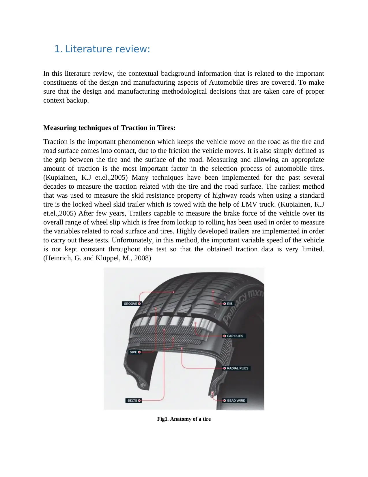
Fig1. Anatomy of a tire
In this literature review, the contextual background information that is related to the important
constituents of the design and manufacturing aspects of Automobile tires are covered. To make
sure that the design and manufacturing methodological decisions that are taken care of proper
context backup.
Measuring techniques of Traction in Tires:
Traction is the important phenomenon which keeps the vehicle move on the road as the tire and
road surface comes into contact, due to the friction the vehicle moves. It is also simply defined as
the grip between the tire and the surface of the road. Measuring and allowing an appropriate
amount of traction is the most important factor in the selection process of automobile tires.
(Kupiainen, K.J et.el.,2005) Many techniques have been implemented for the past several
decades to measure the traction related with the tire and the road surface. The earliest method
that was used to measure the skid resistance property of highway roads when using a standard
tire is the locked wheel skid trailer which is towed with the help of LMV truck. (Kupiainen, K.J
et.el.,2005) After few years, Trailers capable to measure the brake force of the vehicle over its
overall range of wheel slip which is free from lockup to rolling has been used in order to measure
the variables related to road surface and tires. Highly developed trailers are implemented in order
to carry out these tests. Unfortunately, in this method, the important variable speed of the vehicle
is not kept constant throughout the test so that the obtained traction data is very limited.
(Heinrich, G. and Klüppel, M., 2008)
Fig1. Anatomy of a tire
At the National Aeronautics and Space Administration (NASA) Langley Research and
Development centre there is an equipment known as Langley Landing load tracks (Davis, P.A
et.el.,1987). The tire that is to be tested will be mounted on a fixture which is supported by rails.
The whole setup is moved in a high speed over the track which has been constructed uniquely for
the testing purpose. In this, the water depth can also be controlled with very good precision.
(Davis, P.A et.el., 1987). Over the track, a specific portion consists of a plate of broken glass
through which the tire will be passed and the contact of the tire with the broken glass piece will
be photographed and then later used for the examination. This Experimental setup is specifically
used in order to measure the performance of the tires that are used in the aircraft. The traction
performance and the hydroplaning effects of the airplane tires are measured using this setup.
Only a few experiments are done using the automobile tires in this facility (Joyner, U.T et.el.,
1963).
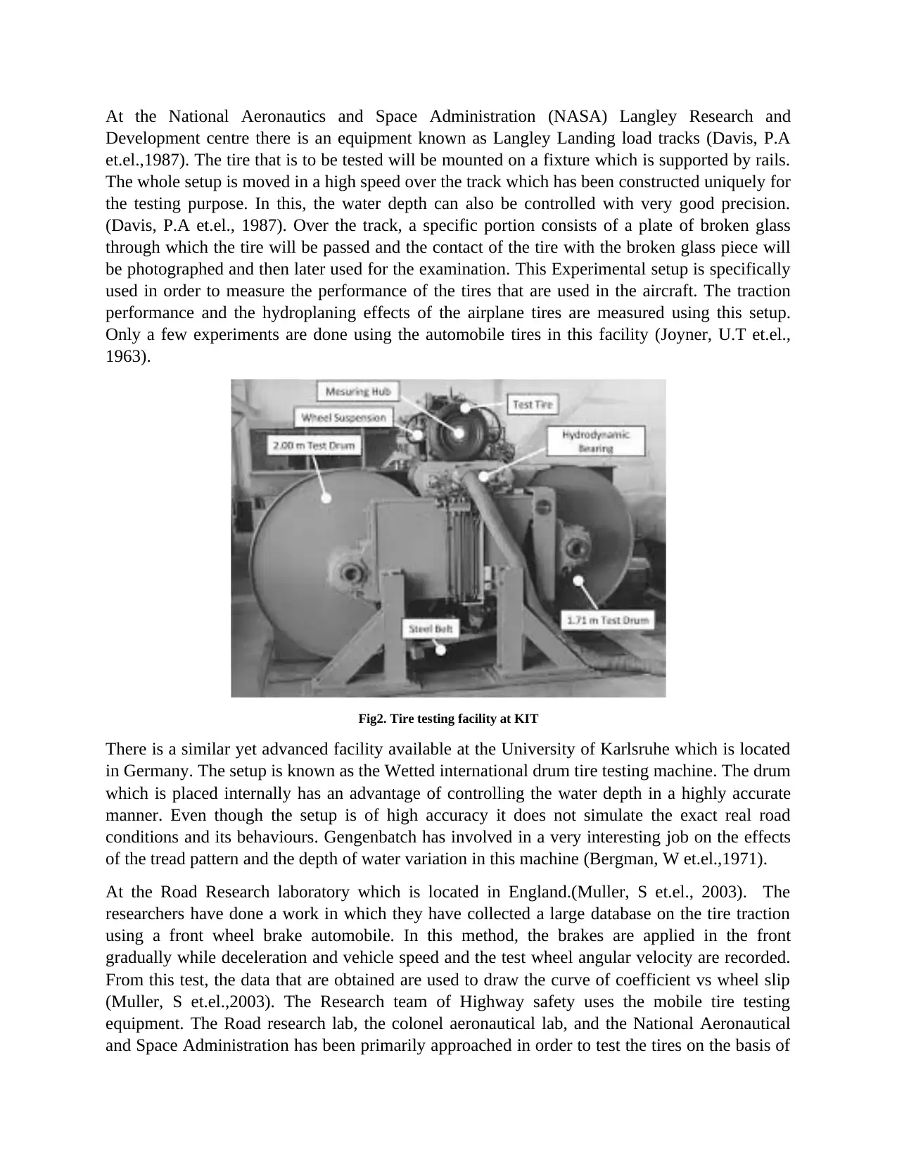
Fig2. Tire testing facility at KIT
There is a similar yet advanced facility available at the University of Karlsruhe which is located
in Germany. The setup is known as the Wetted international drum tire testing machine. The drum
which is placed internally has an advantage of controlling the water depth in a highly accurate
manner. Even though the setup is of high accuracy it does not simulate the exact real road
conditions and its behaviours. Gengenbatch has involved in a very interesting job on the effects
of the tread pattern and the depth of water variation in this machine (Bergman, W et.el.,1971).
At the Road Research laboratory which is located in England.(Muller, S et.el., 2003). The
researchers have done a work in which they have collected a large database on the tire traction
using a front wheel brake automobile. In this method, the brakes are applied in the front
gradually while deceleration and vehicle speed and the test wheel angular velocity are recorded.
From this test, the data that are obtained are used to draw the curve of coefficient vs wheel slip
(Muller, S et.el.,2003). The Research team of Highway safety uses the mobile tire testing
equipment. The Road research lab, the colonel aeronautical lab, and the National Aeronautical
and Space Administration has been primarily approached in order to test the tires on the basis of
Development centre there is an equipment known as Langley Landing load tracks (Davis, P.A
et.el.,1987). The tire that is to be tested will be mounted on a fixture which is supported by rails.
The whole setup is moved in a high speed over the track which has been constructed uniquely for
the testing purpose. In this, the water depth can also be controlled with very good precision.
(Davis, P.A et.el., 1987). Over the track, a specific portion consists of a plate of broken glass
through which the tire will be passed and the contact of the tire with the broken glass piece will
be photographed and then later used for the examination. This Experimental setup is specifically
used in order to measure the performance of the tires that are used in the aircraft. The traction
performance and the hydroplaning effects of the airplane tires are measured using this setup.
Only a few experiments are done using the automobile tires in this facility (Joyner, U.T et.el.,
1963).
Fig2. Tire testing facility at KIT
There is a similar yet advanced facility available at the University of Karlsruhe which is located
in Germany. The setup is known as the Wetted international drum tire testing machine. The drum
which is placed internally has an advantage of controlling the water depth in a highly accurate
manner. Even though the setup is of high accuracy it does not simulate the exact real road
conditions and its behaviours. Gengenbatch has involved in a very interesting job on the effects
of the tread pattern and the depth of water variation in this machine (Bergman, W et.el.,1971).
At the Road Research laboratory which is located in England.(Muller, S et.el., 2003). The
researchers have done a work in which they have collected a large database on the tire traction
using a front wheel brake automobile. In this method, the brakes are applied in the front
gradually while deceleration and vehicle speed and the test wheel angular velocity are recorded.
From this test, the data that are obtained are used to draw the curve of coefficient vs wheel slip
(Muller, S et.el.,2003). The Research team of Highway safety uses the mobile tire testing
equipment. The Road research lab, the colonel aeronautical lab, and the National Aeronautical
and Space Administration has been primarily approached in order to test the tires on the basis of
⊘ This is a preview!⊘
Do you want full access?
Subscribe today to unlock all pages.
Trusted by 1+ million students worldwide
the application of vehicle dynamics and the simulation is also done. Generally, all of these
machines are implemented in order to find the characteristics of generation of shear force in a
vehicle resulting due to the simultaneous cornering and the braking effort (McHenry, R.R.,
1968).The Longitudinal braking slip during the cornering characteristics of the brake upon the
slip characteristics of the tire has seen a significant development in the field of development of
tire.(Muller, S et.el., 2003).(Browne, A.L. and Whicker, D., 1983) (Bergman, W et.el., 1971).
Wet surface testing:
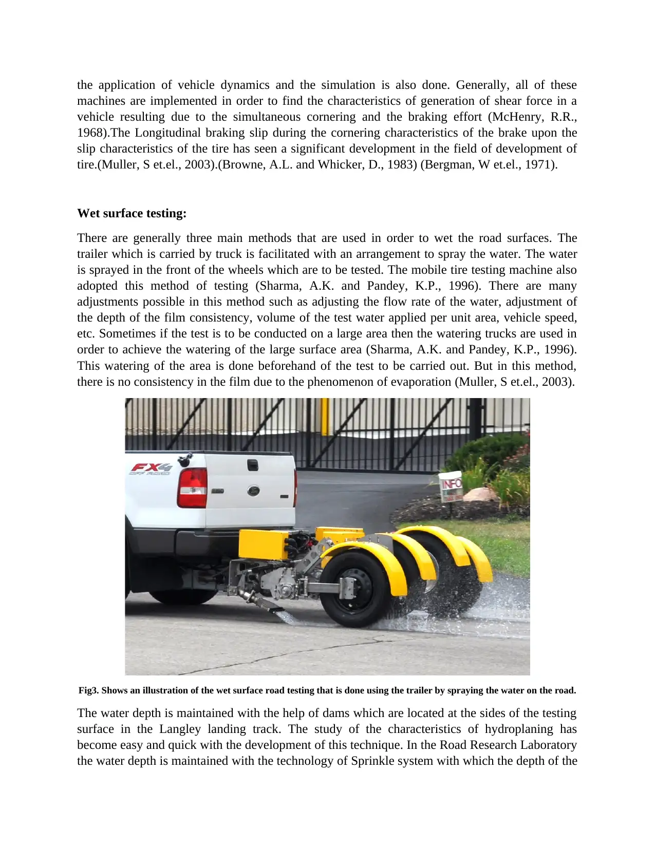
There are generally three main methods that are used in order to wet the road surfaces. The
trailer which is carried by truck is facilitated with an arrangement to spray the water. The water
is sprayed in the front of the wheels which are to be tested. The mobile tire testing machine also
adopted this method of testing (Sharma, A.K. and Pandey, K.P., 1996). There are many
adjustments possible in this method such as adjusting the flow rate of the water, adjustment of
the depth of the film consistency, volume of the test water applied per unit area, vehicle speed,
etc. Sometimes if the test is to be conducted on a large area then the watering trucks are used in
order to achieve the watering of the large surface area (Sharma, A.K. and Pandey, K.P., 1996).
This watering of the area is done beforehand of the test to be carried out. But in this method,
there is no consistency in the film due to the phenomenon of evaporation (Muller, S et.el., 2003).
Fig3. Shows an illustration of the wet surface road testing that is done using the trailer by spraying the water on the road.
The water depth is maintained with the help of dams which are located at the sides of the testing
surface in the Langley landing track. The study of the characteristics of hydroplaning has
become easy and quick with the development of this technique. In the Road Research Laboratory
the water depth is maintained with the technology of Sprinkle system with which the depth of the
machines are implemented in order to find the characteristics of generation of shear force in a
vehicle resulting due to the simultaneous cornering and the braking effort (McHenry, R.R.,
1968).The Longitudinal braking slip during the cornering characteristics of the brake upon the
slip characteristics of the tire has seen a significant development in the field of development of
tire.(Muller, S et.el., 2003).(Browne, A.L. and Whicker, D., 1983) (Bergman, W et.el., 1971).
Wet surface testing:
There are generally three main methods that are used in order to wet the road surfaces. The
trailer which is carried by truck is facilitated with an arrangement to spray the water. The water
is sprayed in the front of the wheels which are to be tested. The mobile tire testing machine also
adopted this method of testing (Sharma, A.K. and Pandey, K.P., 1996). There are many
adjustments possible in this method such as adjusting the flow rate of the water, adjustment of
the depth of the film consistency, volume of the test water applied per unit area, vehicle speed,
etc. Sometimes if the test is to be conducted on a large area then the watering trucks are used in
order to achieve the watering of the large surface area (Sharma, A.K. and Pandey, K.P., 1996).
This watering of the area is done beforehand of the test to be carried out. But in this method,
there is no consistency in the film due to the phenomenon of evaporation (Muller, S et.el., 2003).
Fig3. Shows an illustration of the wet surface road testing that is done using the trailer by spraying the water on the road.
The water depth is maintained with the help of dams which are located at the sides of the testing
surface in the Langley landing track. The study of the characteristics of hydroplaning has
become easy and quick with the development of this technique. In the Road Research Laboratory
the water depth is maintained with the technology of Sprinkle system with which the depth of the
Paraphrase This Document
Need a fresh take? Get an instant paraphrase of this document with our AI Paraphraser
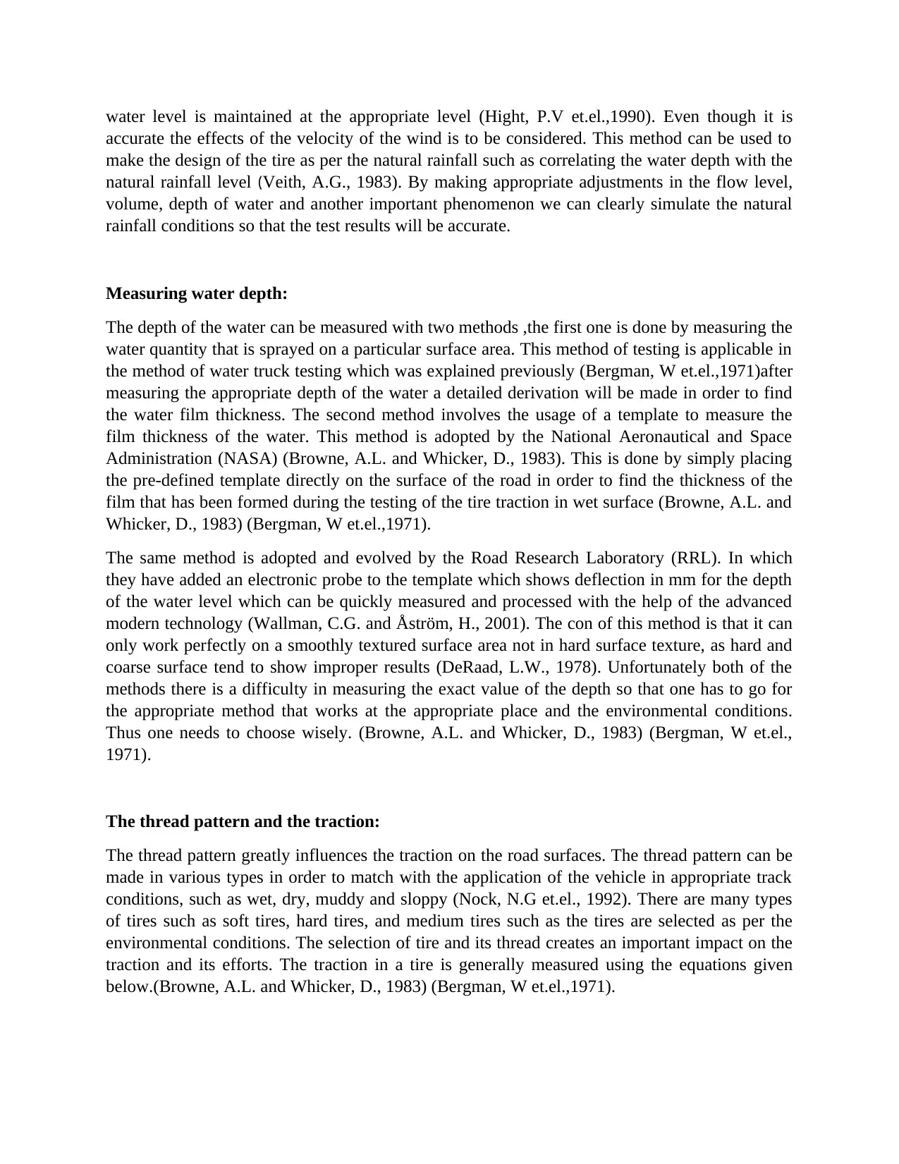
water level is maintained at the appropriate level (Hight, P.V et.el.,1990). Even though it is
accurate the effects of the velocity of the wind is to be considered. This method can be used to
make the design of the tire as per the natural rainfall such as correlating the water depth with the
natural rainfall level (Veith, A.G., 1983). By making appropriate adjustments in the flow level,
volume, depth of water and another important phenomenon we can clearly simulate the natural
rainfall conditions so that the test results will be accurate.
Measuring water depth:
The depth of the water can be measured with two methods ,the first one is done by measuring the
water quantity that is sprayed on a particular surface area. This method of testing is applicable in
the method of water truck testing which was explained previously (Bergman, W et.el.,1971)after
measuring the appropriate depth of the water a detailed derivation will be made in order to find
the water film thickness. The second method involves the usage of a template to measure the
film thickness of the water. This method is adopted by the National Aeronautical and Space
Administration (NASA) (Browne, A.L. and Whicker, D., 1983). This is done by simply placing
the pre-defined template directly on the surface of the road in order to find the thickness of the
film that has been formed during the testing of the tire traction in wet surface (Browne, A.L. and
Whicker, D., 1983) (Bergman, W et.el.,1971).
The same method is adopted and evolved by the Road Research Laboratory (RRL). In which
they have added an electronic probe to the template which shows deflection in mm for the depth
of the water level which can be quickly measured and processed with the help of the advanced
modern technology (Wallman, C.G. and Åström, H., 2001). The con of this method is that it can
only work perfectly on a smoothly textured surface area not in hard surface texture, as hard and
coarse surface tend to show improper results (DeRaad, L.W., 1978). Unfortunately both of the
methods there is a difficulty in measuring the exact value of the depth so that one has to go for
the appropriate method that works at the appropriate place and the environmental conditions.
Thus one needs to choose wisely. (Browne, A.L. and Whicker, D., 1983) (Bergman, W et.el.,
1971).
The thread pattern and the traction:
The thread pattern greatly influences the traction on the road surfaces. The thread pattern can be
made in various types in order to match with the application of the vehicle in appropriate track
conditions, such as wet, dry, muddy and sloppy (Nock, N.G et.el., 1992). There are many types
of tires such as soft tires, hard tires, and medium tires such as the tires are selected as per the
environmental conditions. The selection of tire and its thread creates an important impact on the
traction and its efforts. The traction in a tire is generally measured using the equations given
below.(Browne, A.L. and Whicker, D., 1983) (Bergman, W et.el.,1971).
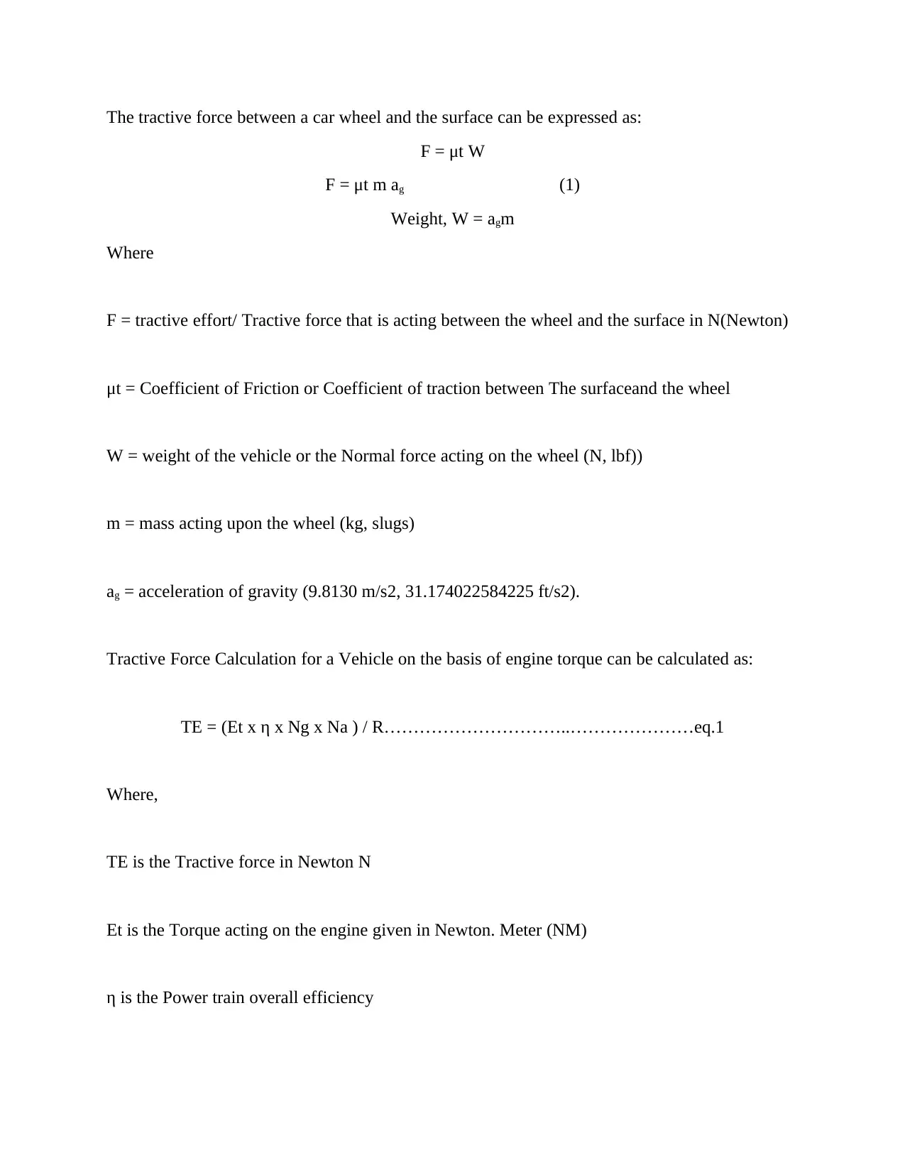
The tractive force between a car wheel and the surface can be expressed as:
F = μt W
F = μt m ag (1)
Weight, W = agm
Where
F = tractive effort/ Tractive force that is acting between the wheel and the surface in N(Newton)
μt = Coefficient of Friction or Coefficient of traction between The surfaceand the wheel
W = weight of the vehicle or the Normal force acting on the wheel (N, lbf))
m = mass acting upon the wheel (kg, slugs)
ag = acceleration of gravity (9.8130 m/s2, 31.174022584225 ft/s2).
Tractive Force Calculation for a Vehicle on the basis of engine torque can be calculated as:
TE = (Et x η x Ng x Na ) / R…………………………..…………………eq.1
Where,
TE is the Tractive force in Newton N
Et is the Torque acting on the engine given in Newton. Meter (NM)
η is the Power train overall efficiency
⊘ This is a preview!⊘
Do you want full access?
Subscribe today to unlock all pages.
Trusted by 1+ million students worldwide
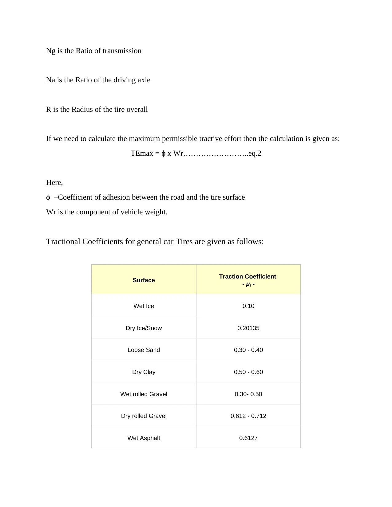
Ng is the Ratio of transmission
Na is the Ratio of the driving axle
R is the Radius of the tire overall
If we need to calculate the maximum permissible tractive effort then the calculation is given as:
TEmax = ϕ x Wr……………………..eq.2
Here,
ϕ –Coefficient of adhesion between the road and the tire surface
Wr is the component of vehicle weight.
Tractional Coefficients for general car Tires are given as follows:
Surface Traction Coefficient
- μt -
Wet Ice 0.10
Dry Ice/Snow 0.20135
Loose Sand 0.30 - 0.40
Dry Clay 0.50 - 0.60
Wet rolled Gravel 0.30- 0.50
Dry rolled Gravel 0.612 - 0.712
Wet Asphalt 0.6127
Paraphrase This Document
Need a fresh take? Get an instant paraphrase of this document with our AI Paraphraser
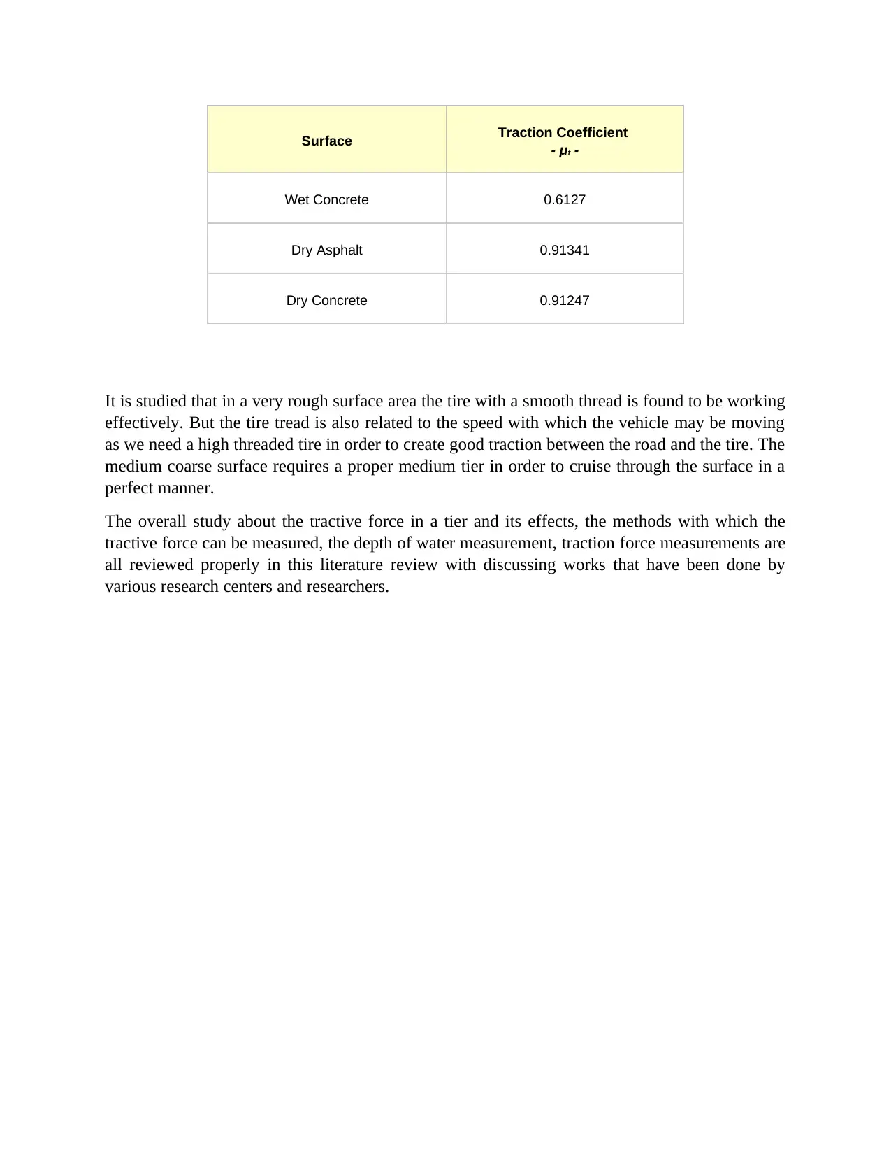
Surface Traction Coefficient
- μt -
Wet Concrete 0.6127
Dry Asphalt 0.91341
Dry Concrete 0.91247
It is studied that in a very rough surface area the tire with a smooth thread is found to be working
effectively. But the tire tread is also related to the speed with which the vehicle may be moving
as we need a high threaded tire in order to create good traction between the road and the tire. The
medium coarse surface requires a proper medium tier in order to cruise through the surface in a
perfect manner.
The overall study about the tractive force in a tier and its effects, the methods with which the
tractive force can be measured, the depth of water measurement, traction force measurements are
all reviewed properly in this literature review with discussing works that have been done by
various research centers and researchers.
References:
Bergman, W., Clemett, H.R. and Sheth, N.J., (1971). Tire Traction Measurement on the Road
and in the Laboratory. SAE Transactions, pp.2330-2351.
Browne, A.L. and Whicker, D., (1983). An interactive tire-fluid model for dynamic
hydroplaning. In Frictional interaction of tire and pavement. ASTM International.
Davis, P.A., Stubbs, S.M. and Tanner, J.A., (1987). Langley aircraft landing dynamics facility
(Vol. 1189). National Aeronautics and Space Administration, Scientific and Technical
Information Office.
DeRaad, L.W., (1978). The influence of road surface texture on tire rolling resistance (No.
780257). SAE Technical Paper.
Heinrich, G. and Klüppel, M., 2008. Rubber friction, tread deformation and tire
traction. Wear, 265(7-8), pp.1052-1060.
Hight, P.V., Wheeler, J.B., Reust, T.J. and Birch, N., (1990). The effects of right side water drag
on vehicle dynamics and accident causation (No. 900105). SAE Technical Paper.
Joyner, U.T., Horne, W.B. and Leland, T.J., (1963). Investigations on the Ground Performance
of Aircraft Relating to Wet Runway Braking and Slush Drag. ADVISORY GROUP FOR
AERONAUTICAL RESEARCH AND DEVELOPMENT PARIS (FRANCE).
Kupiainen, K.J., Tervahattu, H., Räisänen, M., Mäkelä, T., Aurela, M. and Hillamo, R., (2005).
Size and composition of airborne particles from pavement wear, tires, and traction
sanding.Environmental science & technology, 39(3), pp.699-706.
McHenry, R.R., (1968), September. Paper 3: An Analysis of the Dynamics of Automobiles
during Simultaneous Cornering and Ride Motions. In Proceedings of the Institution of
Mechanical Engineers, Conference Proceedings (Vol. 183, No. 8, pp. 61-81). Sage UK: London,
England: SAGE Publications.
Muller, S., Uchanski, M. and Hedrick, K., (2003). Estimation of the maximum tire-road friction
coefficient. Journal of dynamic systems, measurement, and control, 125(4), pp.607-617.
Nock, N.G., Clarke, D.H. and Martin, J., Sumitomo Rubber Industries Ltd, (1992). Tire tread
pattern having transverse grooves with interlocking noise baffles. U.S. Patent 5,147,478.
Sharma, A.K. and Pandey, K.P., (1996). A review on contact area measurement of a pneumatic
tyre on rigid and deformable surfaces. Journal of Terramechanics, 33(5), pp.253-264.
Wallman, C.G. and Åström, H., (2001). Friction measurement methods and the correlation
between road friction and traffic safety: A literature review. Statens väg-och
transportforskningsinstitut.
⊘ This is a preview!⊘
Do you want full access?
Subscribe today to unlock all pages.
Trusted by 1+ million students worldwide
1 out of 9
Your All-in-One AI-Powered Toolkit for Academic Success.
+13062052269
info@desklib.com
Available 24*7 on WhatsApp / Email
![[object Object]](/_next/static/media/star-bottom.7253800d.svg)
Unlock your academic potential
Copyright © 2020–2026 A2Z Services. All Rights Reserved. Developed and managed by ZUCOL.