Computer Aided Tool Design: Chip Formation in Cutting Processes
VerifiedAdded on 2022/10/02
|7
|1101
|245
Report
AI Summary
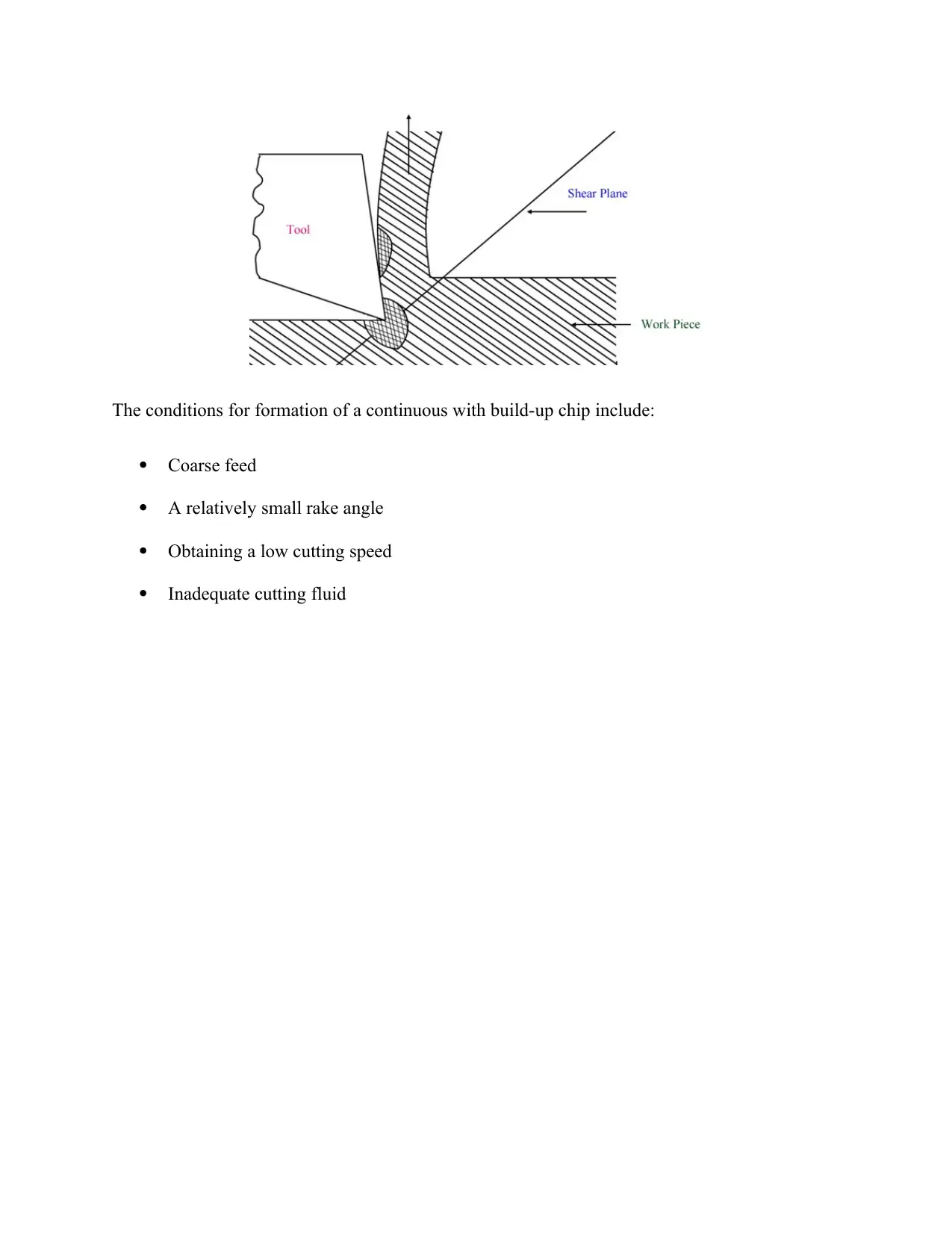
This report provides a comprehensive analysis of chip formation in metal cutting processes. It begins by defining chip formation and its significance in tool design, discussing the classification of chips based on material and tool characteristics. The report details different types of chips, including Type ...

COMPUTER AIDED TOOL DESIGN
By Name
Course
Instructor
Institution
Location
Date
By Name
Course
Instructor
Institution
Location
Date
Paraphrase This Document
Need a fresh take? Get an instant paraphrase of this document with our AI Paraphraser

Chip formation is an aspect of cutting materials process by mechanical means with the use of
tools including lathes, saws as well as milling cutters. A proper comprehension of engineering as
well as theory supporting the formation of chips is an integral element of development of these
machines alongside their cutting tools (Jagtap and Pawade, 2018). Chips are classified based on
numerous factors that are inclined along the material and the tool and generally the main factors
include the angle that is formed between the edge faces of tool as well as the angle of
presentation to the surface. During the process of metal cutting, the removal of tool for formation
of small metal from workpiece is known as chip. The work materials as well as the machine
process method are the determinants of chip types in metal cutting.
The chip type is not necessarily defines by cutting tool sharpness but instead chip quality as well
as the clear distinctions that exist between the various types. A blunt tool generates a degenerate
chip which is big, variant and torn from a single formation means to another normally leaving
behind a surface that has very poor quality in which the means changes (Jagtap and Pawade,
2018).
Type I chips are formed when there is split of material ahead of cutting edge as a result of certain
upwards wedge action by tool going beyond material tensile strength, at right angle to surface.
They are hence specifically significant in fibrous materials for instance wood in which individual
fibres tend to be strong even though they might be levered apart significantly easily. This type of
chips could form long and continuous swarf that are limited in terms of size just by the length of
cut.
Type II chips are formed upon the production of a shearing force by twedge of tool angle. Failure
of material occurs along short angle plane to surface from tool edge apex in a diagonal manner

upwards and in a forward way. The chips are often formed from intermediate cutting angles and
could form in ductile materials for instance metals (Jagtap and Pawade, 2018).
The variable types taken into consideration for the formation of chip include:
Cutting death
Material features of brittleness and ductility
Tool angle for instance rake angle
Rake feed rate
Cutting fluid adopted in machining
Required surface finish of work material
Friction coefficient attained between chip and tools
Type III chips are make a material compression failure before a significantly obtuse cutting
angle, nearing 90⁰. This could result in an acceptable chip in some weak or even non-ductile
materials often in the form of fine dust but normally it results in a random snowplough effect
instead in which waste material tends to be bounced up ahead of tool even though uncleared
decisively away in the form of a well formed chip (Jagtap and Pawade, 2018). The chip is
formed by routers and is as well formed by woodworking scrappers even though when used and
sharpened properly, such form such a relatively thin Type III chip that looked like a well formed
Type II chip.
The types of chip in metal cutting may be classified as:
Continuous chip: A continuous ribbon is offered during ductile material metal cutting as a result
of pressure that is applied on cutting edge of tool in shearing as well as compression. This kind
of chip has a long formation of coil and similar thickness all over the length. The requirement of
⊘ This is a preview!⊘
Do you want full access?
Subscribe today to unlock all pages.

Trusted by 1+ million students worldwide

such kind of chip offer more benefits in the tool, work metal as well as machine. The most
benefits for instance good work material surface finish, tool life would be enhanced and demand
less consumption of power. The disposal of chip is not easy and the work metal surface finish
affected.
The following conditions are to be followed for the formation of continuous chip during the
process of metal cutting:
Smaller depth of cut
Long rake angle
A sharp cutting edge
A high speed of cutting
Use of a proper cutting fluid; and
Maintenance of low friction between chips and tool face
Segmental or discontinuous chips: These are given by use of brittle material for instance high
carbon steel, grey cast iron or bronze subjected to low cutting speed in the absence of a fluid
when there is friction between chip and tools (Razak, Rahman and Kadirgama, 2017). The brittle
materials lacks the ductility during the process of machining of cutting hence there is need for
Paraphrase This Document
Need a fresh take? Get an instant paraphrase of this document with our AI Paraphraser

plastic chip formation which will as well be lesser. There is intermittent occurrence of ruptures in
continuous chip and the chip often has a small length and hence can easily be handled and
disposed of. It as well does not influence the surface finish of work material.
The following conditions need to be met for the formation of discontinuous chip:
Higher depth of cutting
Low speed of cutting
Extra volume of cutting fluid
Small rake angle
Low feeding of cutting of ductile material having a small rake angle
Continuous chip having built up edge: The interface temperature as well as pressure tends to
be high in quickly during the process of metal cutting. Still, there is high friction between tools
and chip and hence the material undergoes welding on its own to the tool face close to the nose.
This is termed as build up edge (Opoz and Chen, 2016).

The conditions for formation of a continuous with build-up chip include:
Coarse feed
A relatively small rake angle
Obtaining a low cutting speed
Inadequate cutting fluid
Coarse feed
A relatively small rake angle
Obtaining a low cutting speed
Inadequate cutting fluid
⊘ This is a preview!⊘
Do you want full access?
Subscribe today to unlock all pages.

Trusted by 1+ million students worldwide

References
Jagtap, K.A. and Pawade, R.S., 2018. Some studies on chip formation mechanism in CNC
turning of biocompatible Co-Cr-Mo alloy. Procedia Manufacturing, 20, pp.283-289
Opoz, T.T. and Chen, X., 2016. Chip formation mechanism using finite element
simulation. Strojniški vestnik-Journal of Mechanical Engineering, 62(11)
Razak, N.H., Rahman, M.M. and Kadirgama, K., 2017. Cutting force and chip formation in end
milling operation when machining nickel-based superalloy, Hastelloy C-2000. J. Mech. Eng.
Sci., 11, pp.2539-2551
1 out of 7

Your All-in-One AI-Powered Toolkit for Academic Success.
+13062052269
info@desklib.com
Available 24*7 on WhatsApp / Email
Unlock your academic potential
© 2024 | Zucol Services PVT LTD | All rights reserved.