Literature Review: Machining Force Models for Metal Matrix Composites
VerifiedAdded on 2023/03/21
|10
|1890
|70
Literature Review
AI Summary
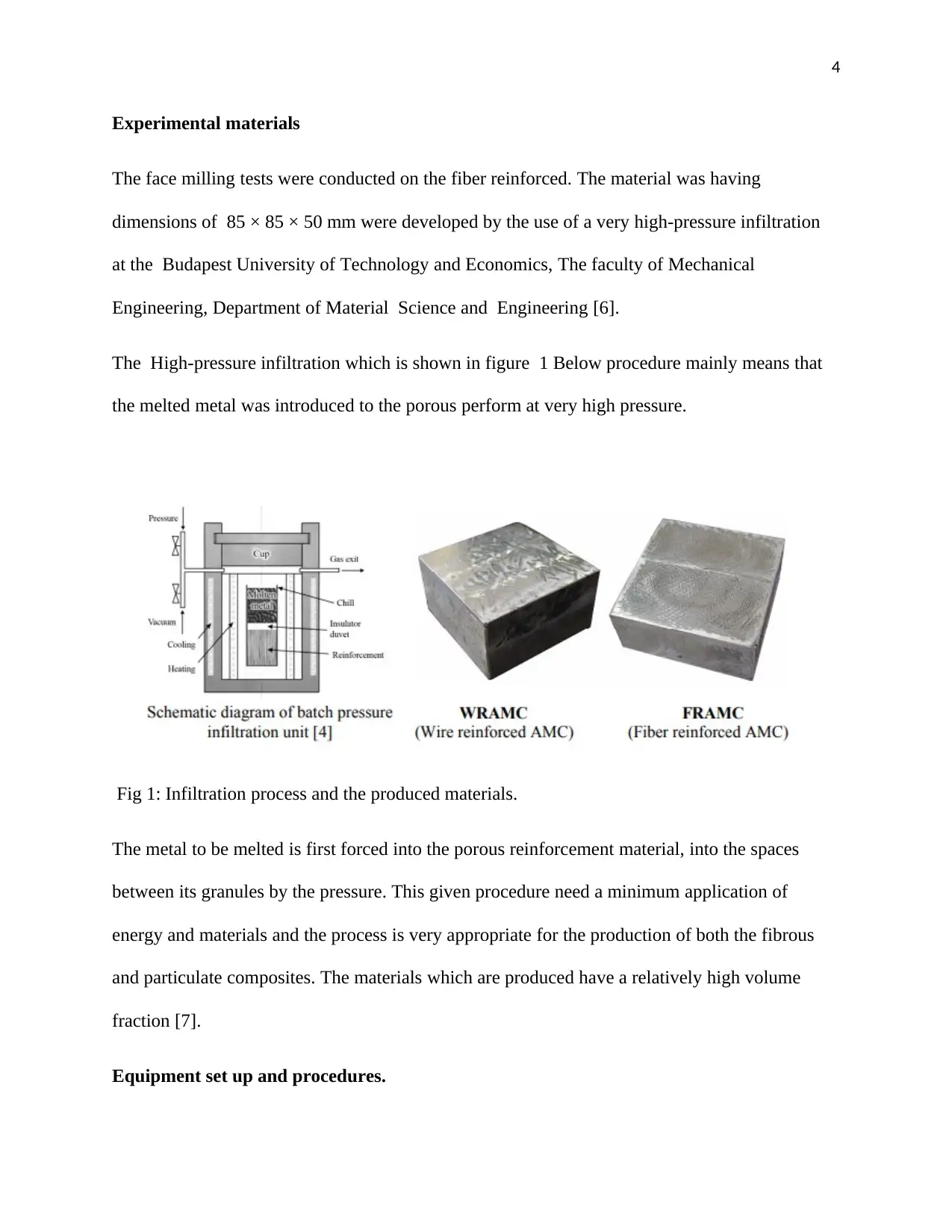
This literature review focuses on machining force models developed for aluminum and magnesium-based metal matrix composites (MMCs). It discusses the challenges in machining MMCs due to the abrasive nature of the reinforcement and high machining costs. The review covers face milling tests conducted on aluminum-based MMCs using coated carbide cutting tools, examining the impact of varying feed rates, width of cut, and depth of cut under constant cutting speed. Key concepts such as cutting force, primary and secondary cutting forces, and the chip forming process are defined. The experimental setup, including materials, equipment, and procedures used in the face milling tests, is detailed, along with the development of finite element models using ABAQUS to simulate the machining process. The review also includes information on the Cook and Johnson constitutive model used for the matrix material and the cohesive zone element method for simulating chip separation. The document concludes with a list of references used in the review.
1 out of 10
Related Documents


Your All-in-One AI-Powered Toolkit for Academic Success.
+13062052269
info@desklib.com
Available 24*7 on WhatsApp / Email
![[object Object]](/_next/static/media/star-bottom.7253800d.svg)
Copyright © 2020–2026 A2Z Services. All Rights Reserved. Developed and managed by ZUCOL.