CE 2.1 Project Report: GPS Microstrip Antenna Design and Analysis
VerifiedAdded on 2021/06/18
|9
|1733
|57
Project
AI Summary
This project report details the design, implementation, and analysis of a GPS microstrip antenna, undertaken at La Trobe University. The project involved designing a rectangular edge-fed patch antenna using software like Antenna Magus and FEKO to receive GPS signals. The report covers the project's background, objectives, the author's role, and the engineering knowledge applied, including impedance matching and linear polarization principles. It details the design considerations, calculations, and experimental results, including VSWR measurements and the number of satellites acquired indoors and outdoors. The report also addresses the challenges faced during frequency measurement and provides solutions. Ultimately, the project successfully produced a GPS receiver antenna, highlighting the application of telecommunications engineering principles. The project provides valuable insights into antenna design, software utilization, and practical implementation in the field of telecommunications.

CE 2.1 Project Information
Name of the project: GPS Microstrip Antenna
Location of the project: La Trobe University, Melbourne Australia
Project Duration: Please fill
Organization: La Trobe University, Melbourne Australia
Role and Designation during the time: Team Member of the project
CE 2.2 Project Background
CE 2.2.1 Characteristics of the project
This project of GPS Microstrip Antenna was my first mini project in engineering
career. The microstrip antenna was made eventually for the purpose of receiving and
transmitting electromagnetic waves. In this project, we had designed as well as tested a
microstrip antenna that is extremely useful for the particular GPS system application by
utilizing separate software and hardware. In the beginning, we had to analyze a primary
estimation for our project with the help of Antenna Magus. Finally, the software selected by
us in this project was Feko. After this, the design was tested where the result of the
specification was compared to the design. The monitored frequency from network analyzer
was 1.5825668 GHz. The patch antenna used was Rectangular edge-fed patch antenna which
has maximum radiation in the direction normal to the plane of patch of antenna. The antenna
used was easy to fabricate and is reliable in comparison to other patch antennas.
CE 2.2.2 Objectives developed for the project
Paraphrase This Document
Need a fresh take? Get an instant paraphrase of this document with our AI Paraphraser

The project of Design of a Double Pipe Heat Exchanger comprises of two important
objectives. The objectives are as follows:
To select an appropriate antenna which can receive signal for GSM system
To be familiar with different type of software like Antenna Magus, FEKO, ALTIUM
To test the designed antenna in different environment and compare the result
To observe the VSWR of the signal using spectrum analyzer
To connect the antenna and observe its different properties
To observe the actual outcomes of the project and compare it with expected outcome
CE 2.2.3 My area of work
This project of GPS Microstrip Antenna was executed properly. Being the
telecommunications engineer, my major area of work was to design the antenna. I made sure
that the design of the project was made perfectly. Moreover, I even had to test the designed
antenna for proper comparison of results. My other area of work in the project was to arrange
for various meetings and gatherings of the project. I did this at the end of every week for
understanding whether the project would be successful or not or whether we are lagging
behind.
CE 2.2.4 Project Group

Figure 1: People involved in the project
CE 2.2.5 My responsibilities throughout the project
I was an important part of the project. I had various important responsibilities within
the project. My first and the foremost responsibility in this project of GPS Microstrip
Antenna was to design the microstrip perfectly. I knew that if the project design was made
perfectly, the project is bound to be a success. My next responsibility was to assist my project
supervisor in the project. The other significant responsibility in this project was to test the
designed antenna. Another important responsibility that I had to execute in this project was
providing guidance to my juniors. I even applied my knowledge and skills within the project
for successfully completing the project.
CE 2.3 Distinctive Activity
CE 2.3.1 Engineering knowledge and skills applied in the project
⊘ This is a preview!⊘
Do you want full access?
Subscribe today to unlock all pages.

Trusted by 1+ million students worldwide
I have utilized my telecommunications engineering skills and knowledge for the
success of the project. I knew that if I will apply my skills and knowledge in the project
properly, it is evident that the project will be a huge success. I am a hardworking person and
have excellent problem solving skills. Moreover, I had previous experiences of other projects;
I utilized my experience in this particular project. My power of critical thinking and
analytical power are also applied here.
CE 2.3.3 Comprehending the Theory of Project
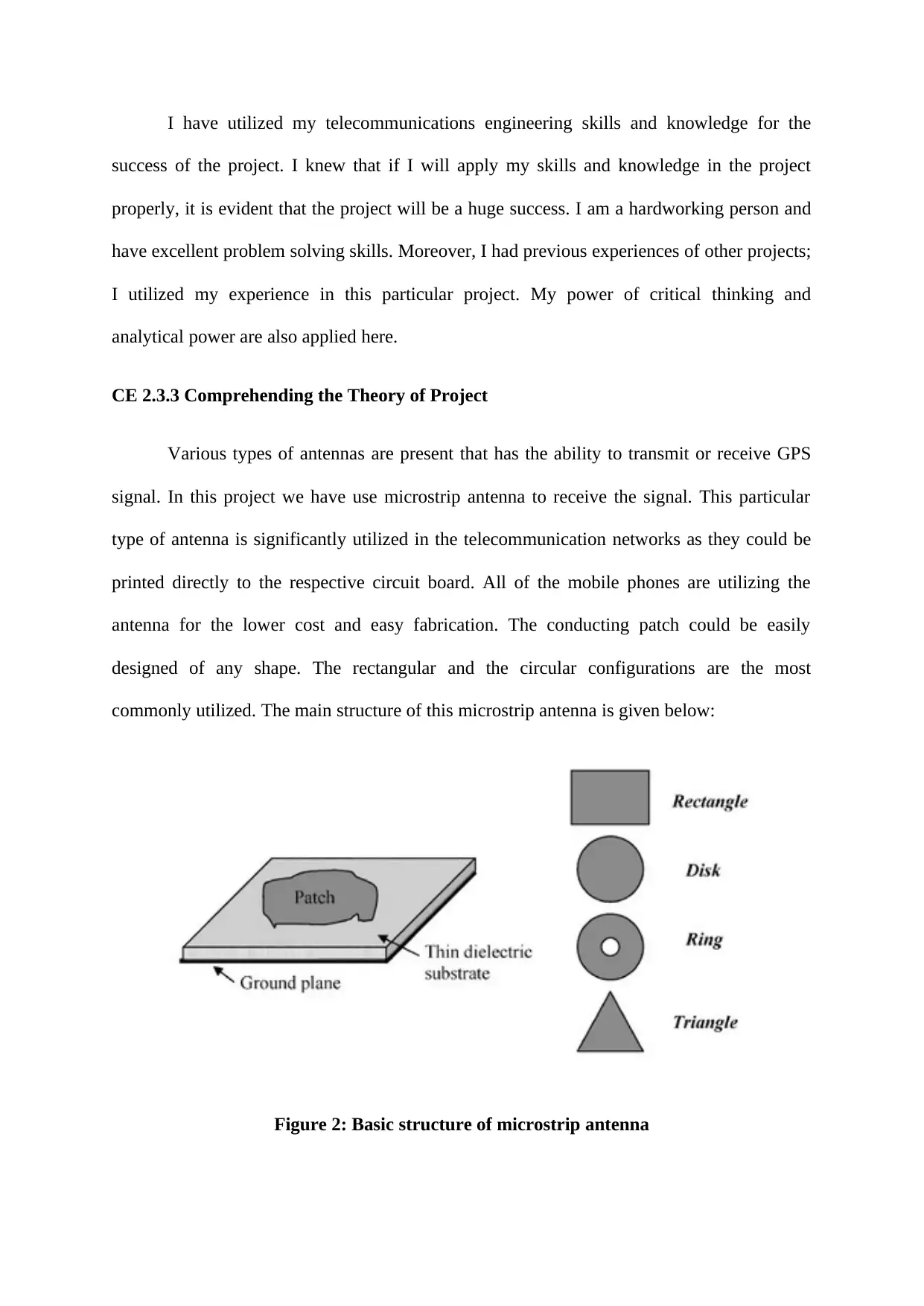
Various types of antennas are present that has the ability to transmit or receive GPS
signal. In this project we have use microstrip antenna to receive the signal. This particular
type of antenna is significantly utilized in the telecommunication networks as they could be
printed directly to the respective circuit board. All of the mobile phones are utilizing the
antenna for the lower cost and easy fabrication. The conducting patch could be easily
designed of any shape. The rectangular and the circular configurations are the most
commonly utilized. The main structure of this microstrip antenna is given below:
Figure 2: Basic structure of microstrip antenna
Paraphrase This Document
Need a fresh take? Get an instant paraphrase of this document with our AI Paraphraser

The temperature, humanity and the environmental factors were considered while
designing any antenna. The most significant benefits of the microstrip antenna are lower cost,
low profile, direct printing on board, designing for multi frequency operations and easy
fabrication. The most significant disadvantages of the microstrip antenna are low gain,
narrow bandwidth, higher loss, low power handling capacity and difficulty in pure
polarization.
The first step in our project was the impedance matching in microstrip antenna.
Impedance matching is an important application in order to improve the performance of a
system in high frequency domain. For matching the impedance, we required to add a
matching network between the source and the load of a system to maximize the power
transfer and to avoid the reflected waves.
The second step in our project was linear polarization. Linear polarization on a given
plane is the combination of the electric field vector or magnetic field vector along a direction
of propagation. For achieving, the full performance of microstrip antenna high polarization
purity and isolation between orthogonal polarizations is needed. For single polarization
systems, the antenna is considered to be a two port device with one port being the interface
with transmitter/receiver and the other port being free space.
The theory calculation for our project is given below:
The radiating rectangular patch antenna length is given by:
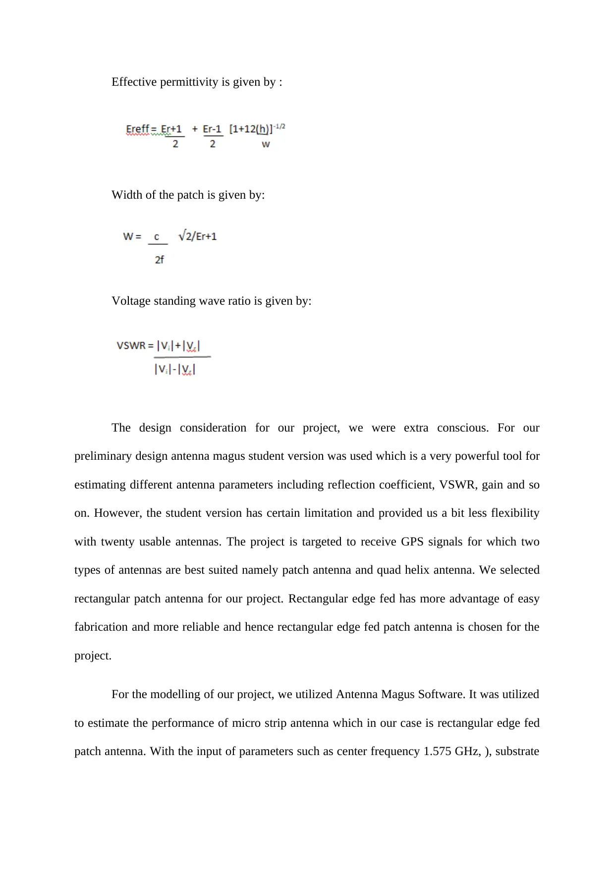
Effective permittivity is given by :
Width of the patch is given by:
Voltage standing wave ratio is given by:
The design consideration for our project, we were extra conscious. For our
preliminary design antenna magus student version was used which is a very powerful tool for
estimating different antenna parameters including reflection coefficient, VSWR, gain and so
on. However, the student version has certain limitation and provided us a bit less flexibility
with twenty usable antennas. The project is targeted to receive GPS signals for which two
types of antennas are best suited namely patch antenna and quad helix antenna. We selected
rectangular patch antenna for our project. Rectangular edge fed has more advantage of easy
fabrication and more reliable and hence rectangular edge fed patch antenna is chosen for the
project.
For the modelling of our project, we utilized Antenna Magus Software. It was utilized
to estimate the performance of micro strip antenna which in our case is rectangular edge fed
patch antenna. With the input of parameters such as center frequency 1.575 GHz, ), substrate
⊘ This is a preview!⊘
Do you want full access?
Subscribe today to unlock all pages.

Trusted by 1+ million students worldwide
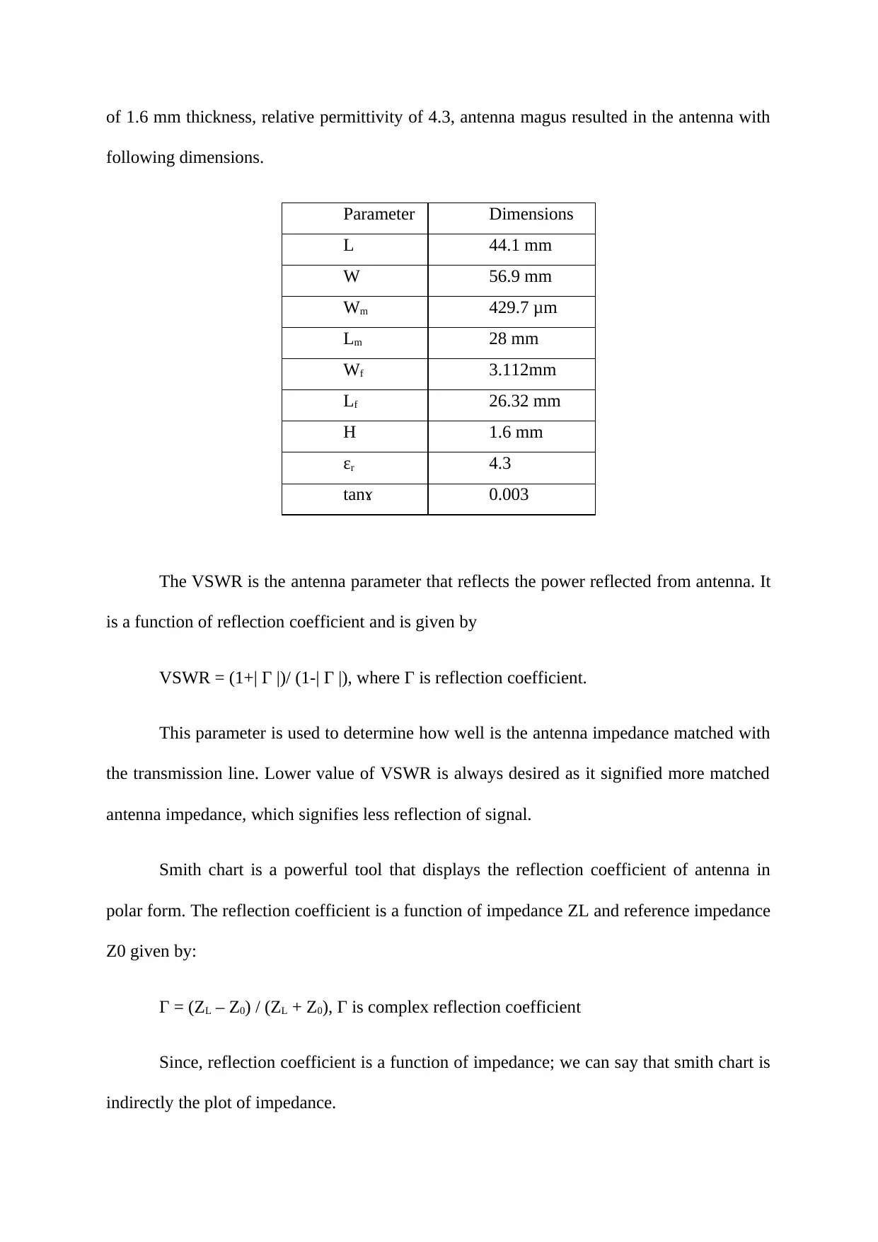
of 1.6 mm thickness, relative permittivity of 4.3, antenna magus resulted in the antenna with
following dimensions.
Parameter Dimensions
L 44.1 mm
W 56.9 mm
Wm 429.7 μm
Lm 28 mm
Wf 3.112mm
Lf 26.32 mm
H 1.6 mm
ɛr 4.3
tanɤ 0.003
The VSWR is the antenna parameter that reflects the power reflected from antenna. It
is a function of reflection coefficient and is given by
VSWR = (1+| Γ |)/ (1-| Γ |), where Γ is reflection coefficient.
This parameter is used to determine how well is the antenna impedance matched with
the transmission line. Lower value of VSWR is always desired as it signified more matched
antenna impedance, which signifies less reflection of signal.
Smith chart is a powerful tool that displays the reflection coefficient of antenna in
polar form. The reflection coefficient is a function of impedance ZL and reference impedance
Z0 given by:
Γ = (ZL – Z0) / (ZL + Z0), Γ is complex reflection coefficient
Since, reflection coefficient is a function of impedance; we can say that smith chart is
indirectly the plot of impedance.
Paraphrase This Document
Need a fresh take? Get an instant paraphrase of this document with our AI Paraphraser
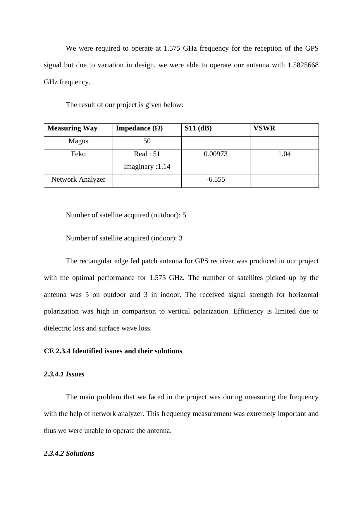
We were required to operate at 1.575 GHz frequency for the reception of the GPS
signal but due to variation in design, we were able to operate our antenna with 1.5825668
GHz frequency.
The result of our project is given below:
Measuring Way Impedance (Ω) S11 (dB) VSWR
Magus 50
Feko Real : 51
Imaginary :1.14
0.00973 1.04
Network Analyzer -6.555
Number of satellite acquired (outdoor): 5
Number of satellite acquired (indoor): 3
The rectangular edge fed patch antenna for GPS receiver was produced in our project
with the optimal performance for 1.575 GHz. The number of satellites picked up by the
antenna was 5 on outdoor and 3 in indoor. The received signal strength for horizontal
polarization was high in comparison to vertical polarization. Efficiency is limited due to
dielectric loss and surface wave loss.
CE 2.3.4 Identified issues and their solutions
2.3.4.1 Issues
The main problem that we faced in the project was during measuring the frequency
with the help of network analyzer. This frequency measurement was extremely important and
thus we were unable to operate the antenna.
2.3.4.2 Solutions

I gave suggestions to my co workers for solving the issue as this was bringing delay in
the project. I gave the idea to operate at 1.575 GHz frequency for the reception of the GPS
signal but due to variation in design.
CE 2.3.5 Plan to produce creative and innovative work
We made a significant plan for our project. Our plan was to bring out creative and
innovative work by working mutually. We divided our work perfectly and every one carried
out their responsibility with utmost sincerity and perfection.
⊘ This is a preview!⊘
Do you want full access?
Subscribe today to unlock all pages.

Trusted by 1+ million students worldwide
1 out of 9
Related Documents
Your All-in-One AI-Powered Toolkit for Academic Success.
+13062052269
info@desklib.com
Available 24*7 on WhatsApp / Email
![[object Object]](/_next/static/media/star-bottom.7253800d.svg)
Unlock your academic potential
Copyright © 2020–2026 A2Z Services. All Rights Reserved. Developed and managed by ZUCOL.


