Microstrip Patch Antenna Bandwidth Improvement Using Foam Substrate
VerifiedAdded on 2023/05/28
|12
|2051
|271
Project
AI Summary
This project details the design and implementation of a microstrip patch antenna with improved bandwidth using a foam substrate. The project aims to enhance the antenna's performance for WLAN and WiMAX applications by increasing substrate thickness and incorporating impedance matching techniques. The objectives include designing a G-slot microstrip patch antenna, using foam substrate for operation in the WLAN band (IEEE 802.11a/g), achieving wide bandwidth, high gain, and minimal cost, and comparing measured and simulated performance. The project developer utilized CST Microwave Studio for simulation, analyzed parameters like return loss, voltage standing wave ratio, and radiation pattern, and addressed issues such as foam height calculation and software design challenges, ultimately achieving a return loss of -10 dB with a 12% bandwidth and a gain of 7.3 dBi.

CE 1.1 Project Information
Name of the project: Microstrip Patch Antenna Bandwidth Improvement by Using
Foam Substrate
Location of the project: Please fill
Project Duration: Please fill
Organization: Please fill
Role and Designation during the time: Project Developer
CE 1.2 Project Background
CE 1.2.1 Characteristics of the project
Microstrip patch antenna refers to the antenna that is being fabricated with the help of
microstrip techniques over the PCB or printed circuit board. These antennas are majorly
utilized at the microwave frequencies and the individual microstrip antennas comprise of the
patch of the respective metal foil for various and several shapes over the PCB shapes. Each
and every microstrip antenna is linked to the receiver and transmitter with the help of foil
microstrip transmission line. During this project, I have improved the bandwidth of
microstrip patch antenna by utilizing foam substrate. The proper emergence of various
services such as machine to machine, electronic health, electronic learning and internet of
things eventually require higher data rates within wireless mobile communication calls. I
considered the idea of foam gap for the purpose of overcoming the various limitations of
performance for the microstrip antenna. I have proposed this particular project of antenna
with G-slot and foam method so that the antenna bandwidth is improved and it could operate
Paraphrase This Document
Need a fresh take? Get an instant paraphrase of this document with our AI Paraphraser

at 2.4 GHz. Therefore, in the project, I have got the result of return loss at -10 dB with the
bandwidth of 12% and gain of 7.3 dBi.
CE 1.2.2 Objectives developed for the project
During the project of improvement of bandwidth for microstrip patch antenna with
foam substrate, I realized that it is being applied to the WLAN as well as WiMAX
connection. I had to enhance the total bandwidth of microstrip patch antenna for the
increment of substrate thickness with lower dielectric substrate by the proper incorporation of
several impedance matching as well as feeding of elements with the help of multi resonators.
Therefore, to complete this project with better efficiency, I developed the following
objectives:
To design a G-slot microstrip patch antenna for the purpose of improving the
respective bandwidth.
To complete the designing phenomenon with the help of foam substrate so that it
could operate in the WLAN band and IEEE 802.11a/g.
To ensure that he microstrip antenna could provide wide bandwidth, high gain and
minimal cost.
To fabricate the microstrip patch antenna and then compare the measured
performance with the simulated performance.
To make an experimental set up for completing the project with efficiency and
effectiveness.
To compare and contrast the complete performance of microstrip antenna with as well
as without foam substrate.
To simulate the project with CST microwave studio and analyze the results after
including radiation pattern, voltage standing ratio, reflection coefficients and
bandwidth.

Head of the
Department
Project Supervisor
Project Developer (Me)
CE 1.2.3 My area of work
My area of work was as being the project developer for the project. I have proper
ground experiences for all types of electrical and electronics or telecommunications projects
and hence I endure fundamental knowledge for such work. Therefore, I was selected for
completing the project alone under the significant guidance of our project supervisor. I have
elementary knowledge of microstrip patch antenna, integrated circuits and microprocessors or
computer architecture and hence implementation this particular project was extremely easy
for me. Being a project developer, I undertook the duty of giving regular updates to my
project supervisor.
CE 1.2.4 Project Group
Figure 1: People involved in the project
CE 1.2.5 My responsibilities throughout the project
Being the project developer, it was my duty to execute the project with perfection. My
first responsibility was to propose a design for the G-slot microstrip patch antenna with the
⊘ This is a preview!⊘
Do you want full access?
Subscribe today to unlock all pages.
Trusted by 1+ million students worldwide

help of foam substrate. The idea of this particular project came into my mind since I had
major interest in microstrip antenna. Moreover, due to the compact size and high bandwidth
as well as high gain, G-slot was better than the conventional microstrip antenna. I selected
CST microwave studio for the simulation of project and analysed the results with my desired
output. I designed a G-slot microstrip patch antenna so that it could operate in WLAN band
and IEEE 802.11a/g. I wanted to make such a project, which has the capability of providing
wider bandwidth and high gain. For the purpose of improving the bandwidth of the antenna, I
selected foam substrate. In the beginning, I tested the microstrip patch antenna without foam
and observed that the results were not matching with my desired output. Hence, I applied
foam substrate in the project and got subsequent results.
CE 1.3 Distinctive Activity
CE 1.3.1 Comprehending the Theory of Project
In the project of MA, I have designed microstrip patch antenna due to the advantages
of resonant frequencies, impedance, patterns and polarization. I also checked for other
advantages like low profile, low weight, capability of dual and triple frequency, could be
easily integrated with MICs or microwave integrated circuits over foam substrate. I got the
idea to execute this project since the bandwidth of this antenna is low, I wanted to improve
this bandwidth. This could be done with the help of foam substrate and hence I have selected
this substrate for the project. I designed E shape microstrip patch antenna in multilayer
structures for Wi-Fi 5 GHz network. Due to the gain and bandwidth enhancement, the
circular microstrip patch antenna was being utilized within two distinct substrates.
I calculated the return loss of the antenna with air gap and got the following result.
Paraphrase This Document
Need a fresh take? Get an instant paraphrase of this document with our AI Paraphraser

Figure 2: Return Loss of Antenna
For improving the gain of circular patches, I presented the circular microstrip patch
antenna with foam gap. It was utilised for operating frequency of antenna is 1.8 GHz for the
personal communication systems.
CE 1.3.2 Engineering knowledge and skills applied in the project
To implement the project, I have applied my skills of telecommunication and
electronics engineering. Regarding calculation of return loss, I used my knowledge of physics
and mathematics. Being an excellent student in microprocessor, it was easier for me to get
appropriate results. I have even applied my elementary acquaintance of CST Microwave
Studio software for simulating the project.
CE 1.3.3 Accomplishment and Task Performed
I have completed the task by utilizing aperture coupling for feed of the antenna. I have
utilized foam material method for improving the antenna bandwidth and gain that is being
placed within There were two parts in the project implementation, which were software
designing and hardware designing.

Figure 3: Flowchart of the Project
⊘ This is a preview!⊘
Do you want full access?
Subscribe today to unlock all pages.
Trusted by 1+ million students worldwide
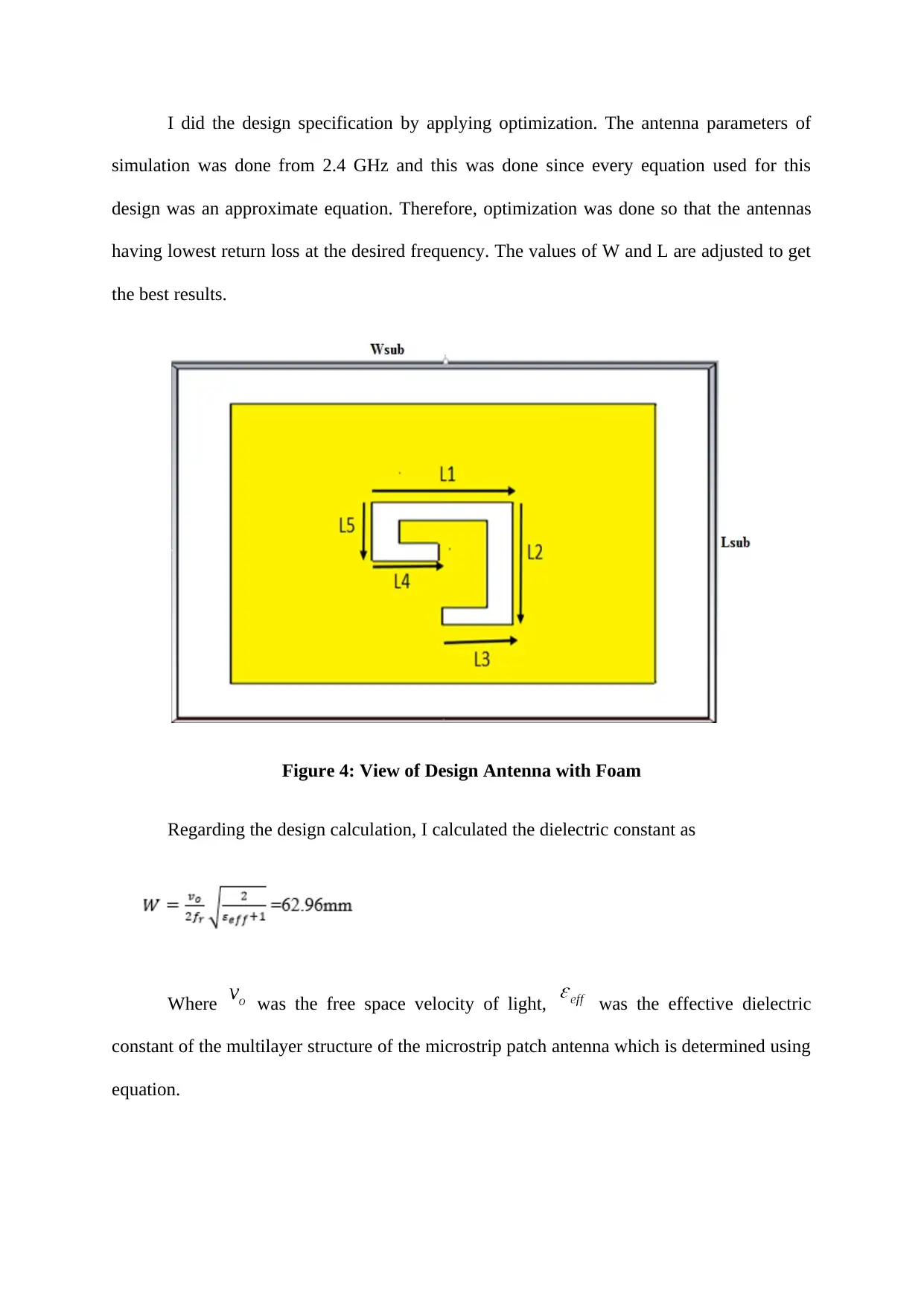
I did the design specification by applying optimization. The antenna parameters of
simulation was done from 2.4 GHz and this was done since every equation used for this
design was an approximate equation. Therefore, optimization was done so that the antennas
having lowest return loss at the desired frequency. The values of W and L are adjusted to get
the best results.
Figure 4: View of Design Antenna with Foam
Regarding the design calculation, I calculated the dielectric constant as
Where was the free space velocity of light, was the effective dielectric
constant of the multilayer structure of the microstrip patch antenna which is determined using
equation.
Paraphrase This Document
Need a fresh take? Get an instant paraphrase of this document with our AI Paraphraser

Regarding the software designing, I have used CST microwave studio to obtain
appropriate measurement results. The significant comparison of the ration of voltage standing
wave, return loss as well as the input impedance was done here.
After simulation with CST software, I got results of return loss, input impedance,
VSWR or voltage standing wave radio, radiation pattern and bandwidth. I compared the
conventional microstrip with my design without foam and selected aperture coupled feed
methods for microwave and monolithic integration. I even obtained effect of length of patch.
Figure 5: Effect of Length of Patch
The width and length decreased when resonant frequencies increased and vice versa.
Figure 6: Feedline Effect of Return Loss (S11)

The overall effect of varying feedline length were obtained with width and length on
return loss of antenna.
After simulating the input impedance, the result obtained was:
Figure 7: Input Impedance of Antenna
Regarding co-polarization, the measurements obtained were:
1 1.2 1.4 1.6 1.8 2 2.2 2.4 2.6 2.8 3
0
2
4
6
8
Frequency (GHz)
Gain(dB)
Gain (Proposed antenna)
Gain (conventional antenna)
Figure 8: Antenna Gain with and without foam
⊘ This is a preview!⊘
Do you want full access?
Subscribe today to unlock all pages.
Trusted by 1+ million students worldwide

After proper comparison, the gain obtained for conventional was 3.4dBi without foam
and that of with foam was 7.3dBi at 2.4GHz frequency. Finally, I measured and simulated
antenna gain with and without foam.
1 1.2 1.4 1.6 1.8 2 2.2 2.4 2.6 2.8 3
1
2
3
4
5
6
7
Frequency (GHz)
Gain (dB)
Sim (With Foam)
Meas(With Foam)
Sim (Without Foam)
Figure 9: Measurement and Simulation of Antenna gain with and without foam
CE 1.3.4 Identified issues and their solutions
1.3.4.1 Issues
The foremost concern, which I have encountered here was while calculating the foam
height in the project. In the beginning, I had undertaken the patch parameters of length 40mm
and weight of 40mm and thus our result was erroneous. The second issue that I have
encountered here was while the software designing of the project. This was the first time that
I have used CST Microwave studio and hence the outputs were not perfect as expected. Being
the project developer, I got the idea of perfect results and hence when I did not get proper
results, I understood the issue.
1.3.4.2 Solutions
Paraphrase This Document
Need a fresh take? Get an instant paraphrase of this document with our AI Paraphraser
For the first issue, I understood that I have to increase the length and width of the
patch parameters. I increased the values to 48mm each and then made these values fixed for
the project. This helped me in resolving the issue and I got proper results effectively. For the
next issue, I took proper training from my supervisor. He gave me trainings and I even
attended few workshops to understand this software. It was quite helpful for me and I was
able to resolve the issue faced here.
CE 1.3.5 Plan to produce creative and innovative works
I have made the distinctive plans to complete the project mechanisms with high
efficacy and efficiency. I have even joined several workshops even before beginning my
work. I have also got correct and exact information about microstrip patch antenna as well as
the integrated circuits.
CE 1.3.6 Collaborative Work
The collaboration for work was the foremost factor for microstrip patch antenna. I
have provided the daily progress reports in front of my supervisor in project. These daily
progress reports were important to identify the major flaws that I had in my work.
CE 1.4 Project Review
CE 1.4.1 Project Overview
I have learnt to design the microstrip patch antenna for improving its bandwidth. For
bandwidth improvement, I have used foam substrate and calculated parametric length and
height of the patch.

Table 1: Parametric Length of Patch
Table 2: Parametric Height of Patch
For software designing, I have used CST Microwave Studio.
CE 1.4.2 My Contribution to work
In this project, I was chosen as the project developer. My primary contribution was to
propose a design for the microstrip patch antenna. I have to resolve every issue faced in the
project use my knowledge of CST Microwave studio for project simulation.
⊘ This is a preview!⊘
Do you want full access?
Subscribe today to unlock all pages.
Trusted by 1+ million students worldwide
1 out of 12
Related Documents


Your All-in-One AI-Powered Toolkit for Academic Success.
+13062052269
info@desklib.com
Available 24*7 on WhatsApp / Email
![[object Object]](/_next/static/media/star-bottom.7253800d.svg)
Unlock your academic potential
Copyright © 2020–2026 A2Z Services. All Rights Reserved. Developed and managed by ZUCOL.