Microwave Link Calculation and Passive Repeater Analysis - ITC513

Verified

Added on  2023/03/31

|7
|734
|93
Homework Assignment
AI Summary
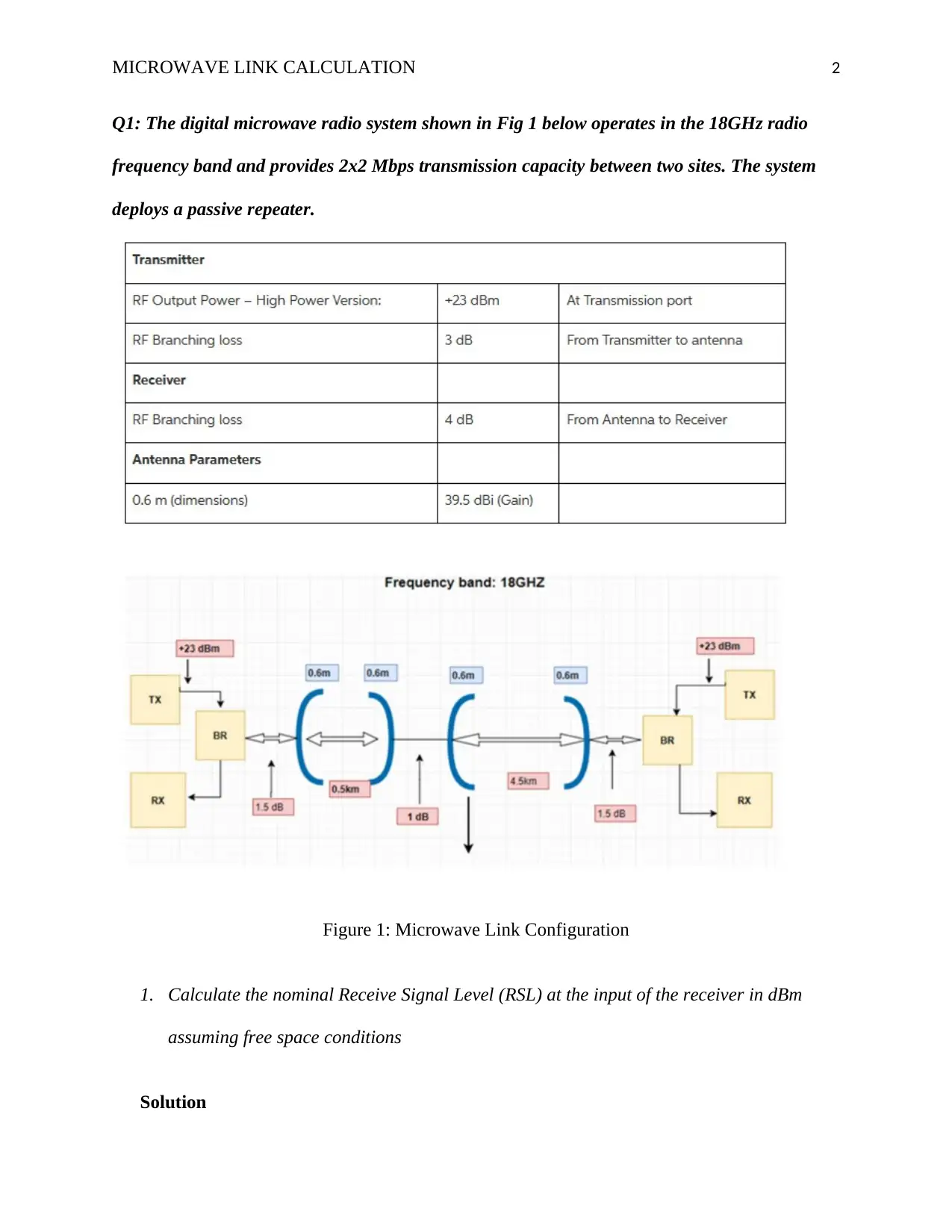
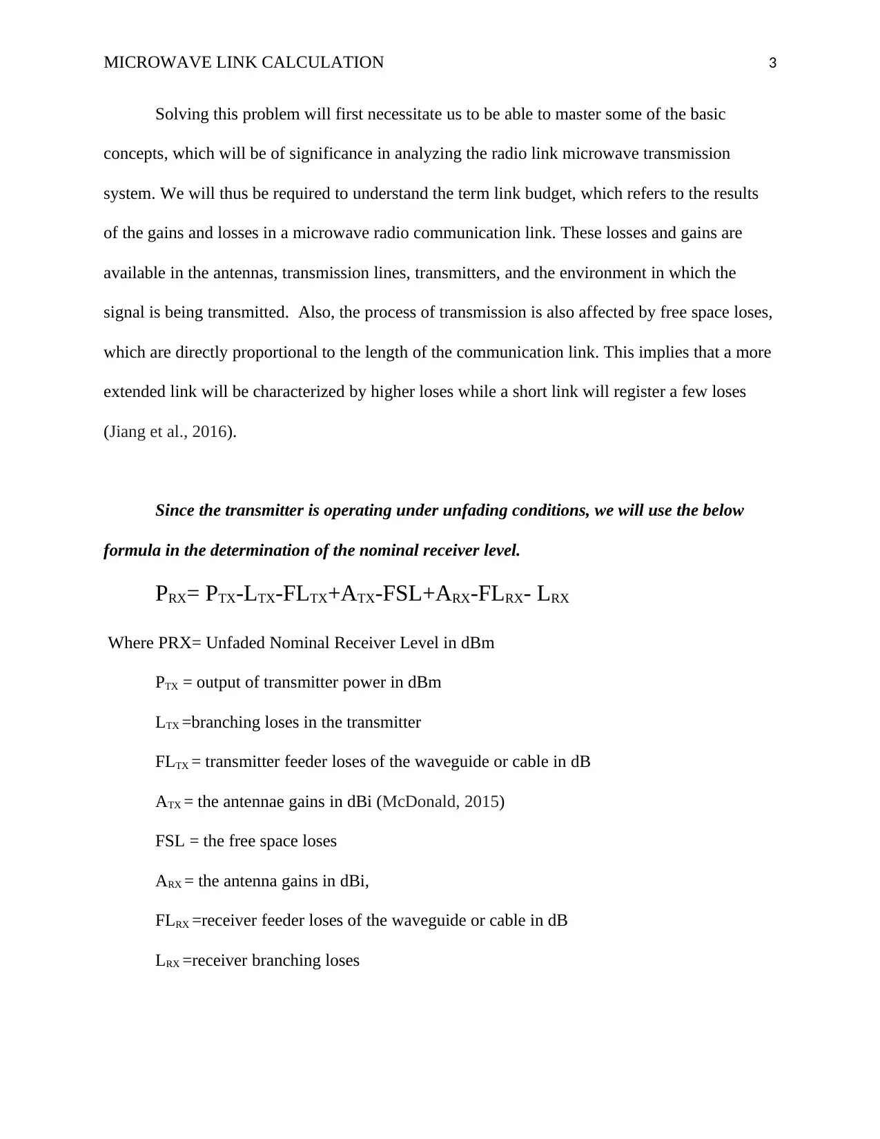
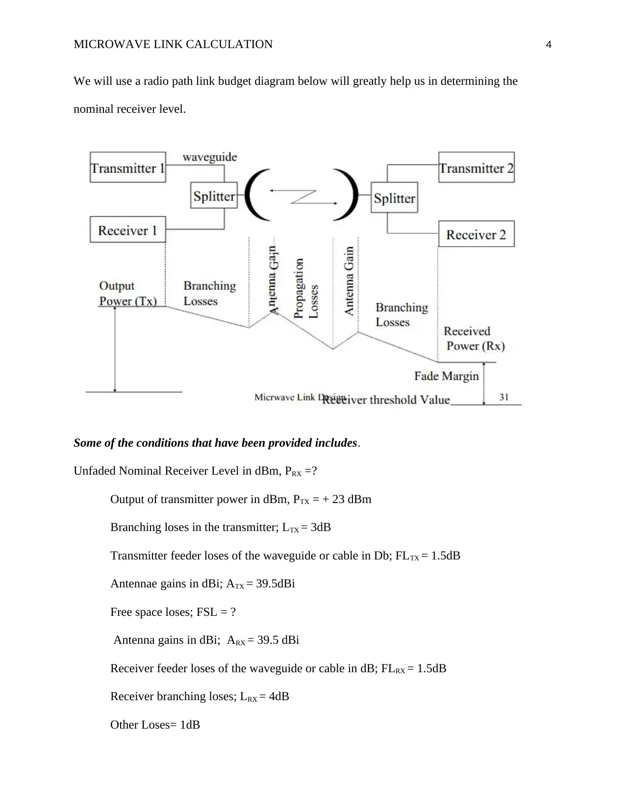
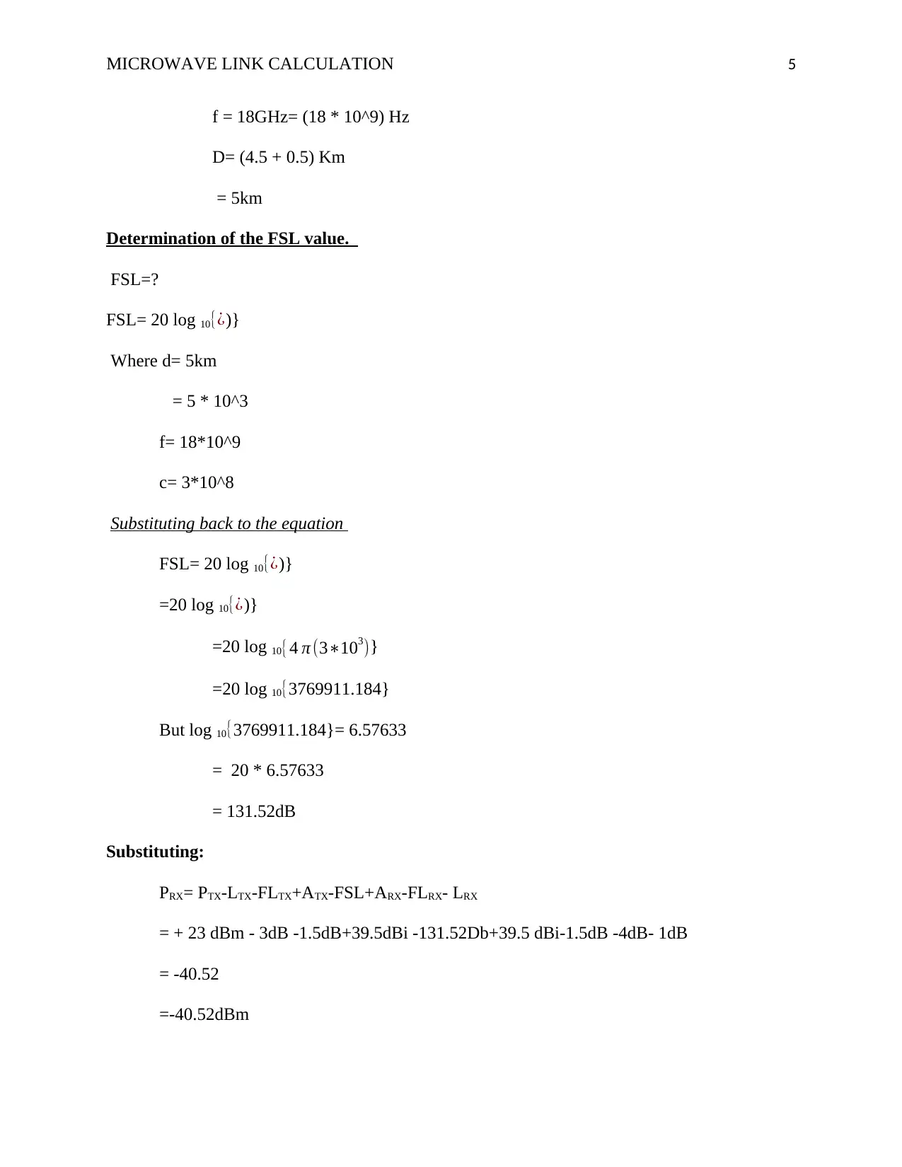
This document provides a comprehensive solution to a microwave link calculation assignment for the ITC513 course. The solution begins with calculating the nominal Receive Signal Level (RSL) at the receiver input, considering factors like transmitter power, branching losses, antenna gains, and free space losses. The calculation utilizes the provided formulas and parameters to arrive at a final RSL value in dBm. Furthermore, the assignment addresses the purpose of passive repeaters in the microwave transmission system, explaining their function as reflective panels to redirect signals obstructed by obstacles. The solution emphasizes the simplicity and cost-effectiveness of passive repeaters in maintaining the link. References to relevant research papers are also included.
Document Page
Running head: MICROWAVE LINK CALCULATION 1
Microwave link calculation
Name of Student
Institution Affiliation
tabler-icon-diamond-filled.svg

Secure Best Marks with AI Grader

Need help grading? Try our AI Grader for instant feedback on your assignments.
Document Page
MICROWAVE LINK CALCULATION 2
Q1: The digital microwave radio system shown in Fig 1 below operates in the 18GHz radio
frequency band and provides 2x2 Mbps transmission capacity between two sites. The system
deploys a passive repeater.
Figure 1: Microwave Link Configuration
1. Calculate the nominal Receive Signal Level (RSL) at the input of the receiver in dBm
assuming free space conditions
Solution
Document Page
MICROWAVE LINK CALCULATION 3
Solving this problem will first necessitate us to be able to master some of the basic
concepts, which will be of significance in analyzing the radio link microwave transmission
system. We will thus be required to understand the term link budget, which refers to the results
of the gains and losses in a microwave radio communication link. These losses and gains are
available in the antennas, transmission lines, transmitters, and the environment in which the
signal is being transmitted. Also, the process of transmission is also affected by free space loses,
which are directly proportional to the length of the communication link. This implies that a more
extended link will be characterized by higher loses while a short link will register a few loses
(Jiang et al., 2016).
Since the transmitter is operating under unfading conditions, we will use the below
formula in the determination of the nominal receiver level.
PRX= PTX-LTX-FLTX+ATX-FSL+ARX-FLRX- LRX
Where PRX= Unfaded Nominal Receiver Level in dBm
PTX = output of transmitter power in dBm
LTX =branching loses in the transmitter
FLTX = transmitter feeder loses of the waveguide or cable in dB
ATX = the antennae gains in dBi (McDonald, 2015)
FSL = the free space loses
ARX = the antenna gains in dBi,
FLRX =receiver feeder loses of the waveguide or cable in dB
LRX =receiver branching loses
Document Page
MICROWAVE LINK CALCULATION 4
We will use a radio path link budget diagram below will greatly help us in determining the
nominal receiver level.
Some of the conditions that have been provided includes.
Unfaded Nominal Receiver Level in dBm, PRX =?
Output of transmitter power in dBm, PTX = + 23 dBm
Branching loses in the transmitter; LTX = 3dB
Transmitter feeder loses of the waveguide or cable in Db; FLTX = 1.5dB
Antennae gains in dBi; ATX = 39.5dBi
Free space loses; FSL = ?
Antenna gains in dBi; ARX = 39.5 dBi
Receiver feeder loses of the waveguide or cable in dB; FLRX = 1.5dB
Receiver branching loses; LRX = 4dB
Other Loses= 1dB
tabler-icon-diamond-filled.svg

Secure Best Marks with AI Grader

Need help grading? Try our AI Grader for instant feedback on your assignments.
Document Page
MICROWAVE LINK CALCULATION 5
f = 18GHz= (18 * 10^9) Hz
D= (4.5 + 0.5) Km
= 5km
Determination of the FSL value.
FSL=?
FSL= 20 log 10{¿)}
Where d= 5km
= 5 * 10^3
f= 18*10^9
c= 3*10^8
Substituting back to the equation
FSL= 20 log 10{¿)}
=20 log 10{¿)}
=20 log 10{4 π (3103)}
=20 log 10{3769911.184}
But log 10{3769911.184}= 6.57633
= 20 * 6.57633
= 131.52dB
Substituting:
PRX= PTX-LTX-FLTX+ATX-FSL+ARX-FLRX- LRX
= + 23 dBm - 3dB -1.5dB+39.5dBi -131.52Db+39.5 dBi-1.5dB -4dB- 1dB
= -40.52
=-40.52dBm
Document Page
MICROWAVE LINK CALCULATION 6
Q2: Purpose of passive repeaters in the microwave transmission
A passive repeater is different from an active repeater is in terms of the structure, power
requirements, and costs of operation. These parameters of differentiation make them be of
different purposes in a radio transmission link. Ordinarily, a passive will perform three essential
functions: acting as a reflective panel, an object, or just a refractive panel that helps in redirecting
a signal which has been obstructed. For this microwave link, the passive repeater acts as a
reflective panel, since there are obstacles around the path of the microwave link, which might
cause interference to the signals that are being transmitted. The passive repeater will then
redirect these signals to the receiver by acting like a beam, reflecting the obstructed signals onto
the surface of the receiver.
The design of the passive repeater is such that it is simple, and thus, it requires low costs
in order to maintain it.
Document Page
MICROWAVE LINK CALCULATION 7
References
Jiang, C., Zhang, H., Ren, Y., Han, Z., Chen, K. C., & Hanzo, L. (2016). Machine learning
paradigms for next-generation wireless networks. IEEE Wireless Communications, 24(2),
98-105.
McDonald, C., (2015, January). Teaching Wireless Networking Through Monitoring. In
International Conference on Computer Science Education Innovation & Technology (CSEIT).
Proceedings, (p. 128). Global Science and Technology Forum
chevron_up_icon
1 out of 7
circle_padding
hide_on_mobile
zoom_out_icon
logo.png

Your All-in-One AI-Powered Toolkit for Academic Success.

Available 24*7 on WhatsApp / Email

[object Object]