MIET 2422 - Fluid Mechanics: Design of Piping Systems for Plant

Verified

Added on  2023/06/04

|11
|2113
|126
Practical Assignment
AI Summary
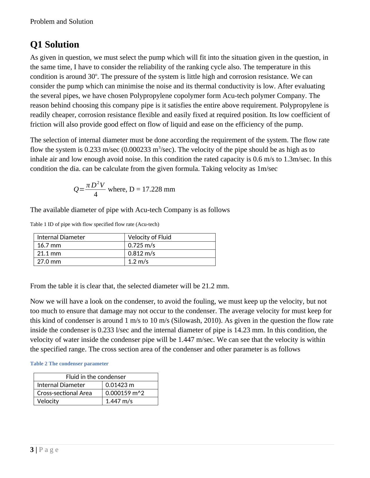
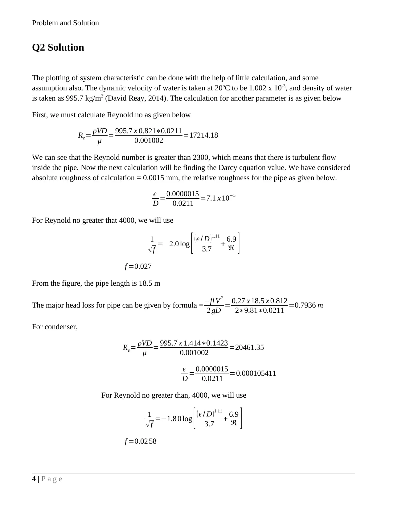
This assignment solution focuses on the design of a piping system for a Rankine cycle solar-powered plant using R134a as the working fluid. It covers the selection of appropriate piping materials (Polypropylene copolymer), calculation of pipe diameter based on flow rate, and analysis of condenser performance. The solution includes detailed calculations for Reynolds number, Darcy friction factor, and major/minor head losses in the piping system. A system characteristic curve is plotted, and a suitable pump (UPA15-90N) is selected based on the system's requirements. The analysis also addresses the Net Positive Suction Head (NPSH) to prevent cavitation and calculates the K-value for flow rate adjustment. Furthermore, the document discusses the factors affecting pump performance over time and provides a bibliography of relevant resources. Desklib offers a wealth of similar solved assignments and past papers for students.
Document Page
Problem and Solution
1 | P a g e
Fluid Mechanics
tabler-icon-diamond-filled.svg

Paraphrase This Document

Need a fresh take? Get an instant paraphrase of this document with our AI Paraphraser
Document Page
Problem and Solution
Contents
Q1 Solution......................................................................................................................................3
Solution 2.........................................................................................................................................3
Solution 3.........................................................................................................................................6
Solution 4.........................................................................................................................................6
Solution 5.........................................................................................................................................7
Solution 6.........................................................................................................................................8
Solution 7.........................................................................................................................................8
2 | P a g e
Document Page
Problem and Solution
Q1 Solution
As given in question, we must select the pump which will fit into the situation given in the question, in
the same time, I have to consider the reliability of the ranking cycle also. The temperature in this
condition is around 30o. The pressure of the system is little high and corrosion resistance. We can
consider the pump which can minimise the noise and its thermal conductivity is low. After evaluating
the several pipes, we have chosen Polypropylene copolymer form Acu-tech polymer Company. The
reason behind choosing this company pipe is it satisfies the entire above requirement. Polypropylene is
readily cheaper, corrosion resistance flexible and easily fixed at required position. Its low coefficient of
friction will also provide good effect on flow of liquid and ease on the efficiency of the pump.
The selection of internal diameter must be done according the requirement of the system. The flow rate
flow the system is 0.233 m/sec (0.000233 m3/sec). The velocity of the pipe should be as high as to
inhale air and low enough avoid noise. In this condition the rated capacity is 0.6 m/s to 1.3m/sec. In this
condition the dia. can be calculate from the given formula. Taking velocity as 1m/sec
Q= π D2 V
4 where, D = 17.228 mm
The available diameter of pipe with Acu-tech Company is as follows
Table 1 ID of pipe with flow specified flow rate (Acu-tech)
Internal Diameter Velocity of Fluid
16.7 mm 0.725 m/s
21.1 mm 0.812 m/s
27.0 mm 1.2 m/s
From the table it is clear that, the selected diameter will be 21.2 mm.
Now we will have a look on the condenser, to avoid the fouling, we must keep up the velocity, but not
too much to ensure that damage may not occur to the condenser. The average velocity for must keep for
this kind of condenser is around 1 m/s to 10 m/s (Silowash, 2010). As given in the question the flow rate
inside the condenser is 0.233 l/sec and the internal diameter of pipe is 14.23 mm. In this condition, the
velocity of water inside the condenser pipe will be 1.447 m/sec. We can see that the velocity is within
the specified range. The cross section area of the condenser and other parameter is as follows
Table 2 The condenser parameter
Fluid in the condenser
Internal Diameter 0.01423 m
Cross-sectional Area 0.000159 m^2
Velocity 1.447 m/s
3 | P a g e
Document Page
Problem and Solution
Q2 Solution
The plotting of system characteristic can be done with the help of little calculation, and some
assumption also. The dynamic velocity of water is taken at 20oC to be 1.002 x 10⁻³, and density of water
is taken as 995.7 kg/m3 (David Reay, 2014). The calculation for another parameter is as given below
First, we must calculate Reynold no as given below
Re= ρVD
μ = 995.7 x 0.8210.0211
0.001002 =17214.18
We can see that the Reynold number is greater than 2300, which means that there is turbulent flow
inside the pipe. Now the next calculation will be finding the Darcy equation value. We have considered
absolute roughness of calculation = 0.0015 mm, the relative roughness for the pipe as given below.
ϵ
D =0.0000015
0.0211 =7.1 x 10⁵
For Reynold no greater that 4000, we will use
1
f =2.0 log [ ( ϵ / D ) 1.11
3.7 + 6.9
]
f =0.027
From the figure, the pipe length is 18.5 m
The major head loss for pipe can be given by formula = fl V 2
2 gD = 0.27 x 18.5 x 0.812
29.810.0211 =0.7936 m
For condenser,
Re= ρVD
μ = 995.7 x 1.4140.1423
0.001002 =20461.35
ϵ
D =0.0000015
0.0211 =0.000105411
For Reynold no greater than, 4000, we will use
1
f =1.8 0 log [ ( ϵ / D )1.11
3.7 + 6.9
]
f =0.02 58
4 | P a g e
tabler-icon-diamond-filled.svg

Paraphrase This Document

Need a fresh take? Get an instant paraphrase of this document with our AI Paraphraser
Document Page
Problem and Solution
The major head loss for condenser can be given by formula =fl V 2
2 gD = 0.2 58 x 7 x 1.414
29.810.01423 =1.3543 m
The main component with their K value
Components K-Value No of parts Total
90o bend 0.9 5 4.5
Shower heads 1 1 1
Globe Valve 10 1 10
Cooling tower inlet 0.5 1 0.5
Strainer 3.6 1 3.6
Total 19.6
180o bend 0.2 6 1.2
As per the table,
The minor losses for pipes = Kx V 2
2 g = 19.6 x 0.812
29.81 =0.6587 m
The minor losses for condenser = Kx V 2
2 g = 1.2 x 1.447
29.81 =0. 1536 m
Therefore,
Htotal=Hmajor condensor + Hmajor pipe+ Hminor condenser+ Hminor pipe+1.5
Htotal=4.46 m
5 | P a g e
Document Page
Problem and Solution
0.00 0.10 0.20 0.30 0.40 0.50 0.60
0
2
4
6
8
10
12
14
System Charcteristic curve
Flow rate (l/s)
Head loss(m)
Figure 1-System characteristic curve
Solution 3
As per given temperature and pressure which is calculated above, we can choose the pump UPA15-90N.
This is due to the reason that pump is suitable for both flow which 0.26 l/s to 0.29 l/sec. is the point of
intersection which is (0.3 flow rate and head loss 5, which means that the characteristic profile curve is
at slight higher than calculated profile, it clearly means that the pump will run at slight lower efficiency.
0.00 0.10 0.20 0.30 0.40 0.50 0.60
0
2
4
6
8
10
12
14
5
SYstem Charecteristic Profile
Flow Rate (l/s)
Head Loss (m)
Figure 2-System curve Total head vs Flow rate
6 | P a g e
Document Page
Problem and Solution
This is due to the reason hat, it depends upon several other factor like, elevation, diameter of piping,
length of piping, pressure drops across various bends and fitting, material used for piping, etc. In this
condition best efficiency point is being chosen for given situation.
In general, the location of the pipe is kept at vertical side of pipe system and it should be away from
strainer, such that efficiency of the strainer is retained.
Solution 4
To know the reason first we have to calculate the (NPSH) which is net positive suction head, The NPSH
for availed pump and what is the required NPSH for the system.
The NPSH for available resources is as follows,
NPSH =hsp hshf hvp
The given term hsp is calculated as follows
hsp= Patm
ρg =10.3287 m and hs = 2.5 m (This is required height of the pump below the
cooling tower. Hf is denoted for head loss in pipe from intel side of the system
hf =h ( major ) p+h ( minor ) pipecondese r
= 0.7936+1.3543+0.6586+0.1537 = 2.9602 m
And finally, hvp= Pv
tvapor
=0.2350 m
The NPSH available = hsp hshf hvp = 10.3287+2.5-2.9602-0.2350 = 9.6334 m
But from the manual it clear that the minimum requirement for given pump is 850 mm, It means that,
we can successfully implement the given pump in the system to avoid the cavitation.
7 | P a g e
tabler-icon-diamond-filled.svg

Paraphrase This Document

Need a fresh take? Get an instant paraphrase of this document with our AI Paraphraser
Document Page
Problem and Solution
Solution 5
As given in the question,
The find the K value for which the flow rate is to be halved. In this condition the velocity Reynolds no
and fiction factor all should be calculated,
Pipe
Condenser
result
Velocity
0.39681
37 0.880503145
Re
8395.65
911 12504.55065
Friction factor (f)
0.03249
957 0.029218623
Based on the above factor we must gain calculate the all losses by keeping the K value for strainer in the
equation, which is as follows
We know that total head loss
4.46=0.61+1.5+ 18.50.3250.962
29.810.212 + ( 9.6+ K valve ) 0.3972
29.81
2.35= 5.54
4.159 + ( 9.6+ Kvalve )0.3972
29.81
( 9.6+ K valve )0.3972
29.81 =1.0178, K = 117.1037 m3/h Ans
8 | P a g e
Document Page
Problem and Solution
0.00 0.10 0.20 0.30 0.40 0.50 0.60
0
2
4
6
8
10
12
14
5
SYstem Charecteristic Profile
Ht(m) Pump H for (q/2)
Flow Rate (l/s)
Head Loss (m)
Figure 3- Flow rate Vs Total head constant graph
Solution 6
The performance of the pump system definitely varies with time, Most of the time its efficiency is
getting reduced, the change in performance may occurs for several reasons, some of the them are as
follows;
Due to vibration in pump,
Wear an wear and tear of impeller clearance ring
Due to Power fluctuation over a long period of time,
Due to wear and tear in impeller and change in geometry etc.
Solution 7
As per the figure and question given, we have selected PP-R pipe for economic factor as well as easy to
handle. The system characteristic is calculated as (0.29, 4.46).
The constant value for f is taken as f = 0.0000015, the graph of flow rate Vs total head is presented for
CPVC pipe. The efficiency of the pump which is considered for operation is around 62%.
The selection of pump was “UPA15-90N ” and selected rpm to obtain best efficiency point is 1450. The
BEP point selected is 396 kg/min at total head around 70 m is calculated.
The explanation for difference in actual BEP and selected BEP is given as a fourth point. We have tried
to find the reason that, why suction is always at high pressure, so that cavitation can be avoided.
9 | P a g e
Document Page
Problem and Solution
The value of K was calculated based on affinity equation and BEP data. The graph for flow rate vs total
head has shown which has constant line after initial fluctuation.
Bibliography
Anon, 2010, Material Selection using CES edupack, Granta Design, pp, 1-57,
Bachus, A, C, 2006, Know and Understand Centrifugal Pumps, 1st ed, Oxford: Elsevier,
Cengel, Y, 2017, Fluid Mechanics, 3rd ed, New York: Mc Graw Hill,
Chaurette, J, 2008, Pump system analysis and sizing, 6th ed, New York: Fluid Design Ink,
Crawford, J, 2016, Marine and Offshore Pumping and Piping Systems, 6th ed, London: Butterworth,
David Reay, R, M, P, K, 2014, Heat Pipes: Theory, Design and Applications, 6th ed, Amestradam:
Elsevier,
Guha, H, a, 2009, The design of a test rig and study of the performance and efficiency of a Tesla disc
turbine, Journal of Power and Energy, 1(1), pp, 451-455,
Gülich, J, F, 2014, Centrifugal Pumps, 3rd ed, New York: Springer,
Robert Jacobs, R, C, 2013, Operations and Supply Chain Management, 14th ed, New York: McGraw-
Hill Higher Education,
Silowash, B, 2010, Piping Systems Manual, 2nd ed, New York: Mc Graw Hill,
Skousen, P, L, 2011, Valve Handbook 3rd Edition, 3rd ed, New York: Mc Graw Hill,
Spellman, F, R, 2017, Water and Wastewater Conveyance: Pumping, Hydraulics, Piping, and Valves,
2nd ed, Boca raton: CRC publisher,
Thomas, C, E, 2015, Process Technology Equipment and Systems, 4th ed, Stanford: Cengage Learning,
White, F, 2013, Fluid Mechanics, 7th ed, New York: Mc Graw Hill,
10 | P a g e
tabler-icon-diamond-filled.svg

Paraphrase This Document

Need a fresh take? Get an instant paraphrase of this document with our AI Paraphraser
Document Page
Problem and Solution
11 | P a g e
chevron_up_icon
1 out of 11
circle_padding
hide_on_mobile
zoom_out_icon
[object Object]