University Name - MIS501: Comprehensive UML Diagram Analysis Report

Verified

Added on  2023/01/17

|11
|1801
|71
Report
AI Summary
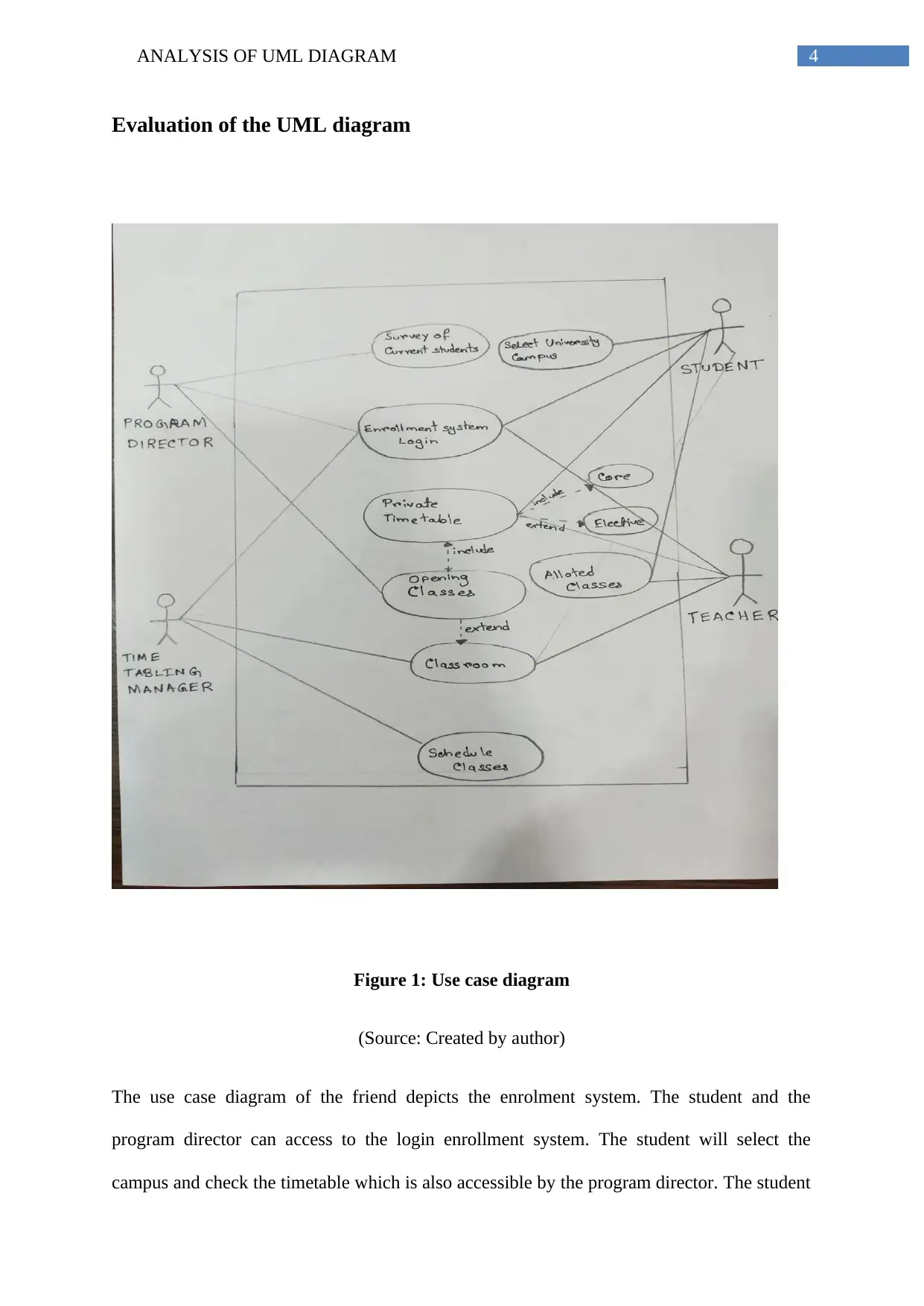
This report provides a critical analysis of a UML diagram, specifically focusing on a use case diagram for an enrollment system. It begins with an introduction to the Unified Modeling Language (UML), explaining its purpose in visualizing, documenting, and constructing software systems. The report then evaluates the provided use case diagram, identifying its strengths and, more importantly, its drawbacks, such as complexity and lack of specific information. It delves into the understanding of UML notations, particularly those used in use case diagrams, and explains the symbols and their meanings. The report also discusses the application of UML diagrams in software design, highlighting their benefits like platform independence and ease of communication. Finally, it concludes by summarizing the benefits and drawbacks of UML diagrams, such as the time-consuming nature of creating and maintaining them, and the need for synchronization with code, while still acknowledging their utility in managing complexity and enhancing visualization.
tabler-icon-diamond-filled.svg

Contribute Materials

Your contribution can guide someone’s learning journey. Share your documents today.
Document Page
Running head: ANALYSIS OF UML DIAGRAM
Analysis of UML Diagram
Name of the Student
Name of the University
Authors note
tabler-icon-diamond-filled.svg

Secure Best Marks with AI Grader

Need help grading? Try our AI Grader for instant feedback on your assignments.
Document Page
1ANALYSIS OF UML DIAGRAM
Executive Summary
The report focuses in providing critical analysis of the UML diagram. The assessment
demonstrates a brief introduction of the UML diagram and understanding the concept of
UML notation. The paper finally concludes by giving the idea of how the developers
encounters several drawbacks while handling the UML diagram.
Document Page
2ANALYSIS OF UML DIAGRAM
Table of Contents
Introduction................................................................................................................................3
Evaluation of the UML diagram................................................................................................4
Understanding the UML Notations........................................................................................5
Application of UML Diagram................................................................................................7
Conclusion..................................................................................................................................7
References:.................................................................................................................................9
Document Page
3ANALYSIS OF UML DIAGRAM
Introduction
Unified Modeling Language (UML) is a kind of language developed to visualize,
document, construct and specify the software system. UML was created by the Object
Management Group, which appeared as a fusion of methods like Booch, OOSE and OMT.
James Rumbaugh, Ivar Jacobson and Grady Booch together developed UML at Rational
Software in the year 1994 to 1996. UML uses graphical notations, which has made it an
important aspect of object-oriented software development (Afanasyev et al., 2015). The aim
of this report is to comment on the suitability of use-case diagram and understanding UML
Notation. The concept of UML is unlike other languages like C++, Python and java. It can
also be used as document to make blueprints of the software (Gómez et al., 2016). The
developers, as well as the common people and software systems as well as non-software
system can use UML. The goal of UML is to provide pictorial model of all system in the
present complex environment. The UML diagram provides a static and dynamic
representation of a system model. The static view comprises of class and composite diagram
that depicts the static outline of the system. UML can be further categoriesed into two broad
categories:
Structural Diagram: Structure diagram comprises of class diagram, object, composite
structural, deployment, component and package diagrams.
Behavioral Diagram: Behavioral diagram comprises of use case diagrams, state machine,
sequence, activity, communication, interaction overview and the timing diagrams (Kumar &
Singh, 2015).
tabler-icon-diamond-filled.svg

Secure Best Marks with AI Grader

Need help grading? Try our AI Grader for instant feedback on your assignments.
Document Page
4ANALYSIS OF UML DIAGRAM
Evaluation of the UML diagram
Figure 1: Use case diagram
(Source: Created by author)
The use case diagram of the friend depicts the enrolment system. The student and the
program director can access to the login enrollment system. The student will select the
campus and check the timetable which is also accessible by the program director. The student
Document Page
5ANALYSIS OF UML DIAGRAM
will select the time as given by the program director. The student can pick the classroom on
the basis of the daily schedule. The time tabling manger will provide the respective
classrooms and schedule the timing of the classes. The teacher will be assigned to the specific
classrooms who will be also responsible to set the private time table. The program director
will have the survey of current student and can also alter the decisions of the time tabling
manager. According to the student’s preference, the classes are assigned to the teacher
(Singh, Sharma & Saxena, 2016). The teaching staff can view the number of students
enrolled and the allocated classrooms. The teaching staff can have access to the time table of
the allotted classrooms. The time tabling manager assigns classes to the teacher and assigns
classroom for the student.
Drawbacks of the Diagram: The diagram which was provided lacked the main ideology of
the use case diagram. The diagram was complex and not specific. There was no information
about the program director should have the data of the progress report of the students who are
applying for the program. Further, the payment procedure was not mentioned that how the
student will pay for the specific course. The diagram was deficient of important functional
requirements. The case study was also not well justified using that diagram. The use case was
unable to capture the important aspects of the enrollment system.
Understanding the UML Notations
A use case diagram is an example of dynamic diagram in UML. This diagram uses
actors to collect the requirement of any system. Use case is used to provide an overview of
any task using dynamic aspect of a system (Gulia & Choudhury, 2016). The UML use case
provides a graphical interaction between the elements of the system. The use case also
benefits in recognizing any external and internal factors of a system. Use case diagrams can
be used to imagine the practical requirement of any system, which can be changed according
Document Page
6ANALYSIS OF UML DIAGRAM
to the development priorities (Savić et al., 2015). They also supply a better level of analysis
from the system externally. Use case diagrams describe the methodology of how a system
interconnects with the actors without bothering the details of how that functionality is
executed.
Symbols used by use case diagram:
System: The rectangle is use to define the boundaries of the system which also
consist the use cases. The actors are always located outside this rectangle.
Use case: The ellipse are used to represent the functions of the system. The dotted
eclipse is used to represent collaborated notation (Jacobson, Spence & Kerr, 2016).
Use case diagram helps to provide a blueprint of any system, for example, restaurant
model, airport security check-in, ticket reservation system and bank ATM.
Actors: The actors represents the user of a system. The actor can indicate either
external or internal entity.
Relation: The arrow head depicts relationship between the actor and the use case.
System name
Use case
Relationship
tabler-icon-diamond-filled.svg

Paraphrase This Document

Need a fresh take? Get an instant paraphrase of this document with our AI Paraphraser
Document Page
7ANALYSIS OF UML DIAGRAM
Application of UML Diagram
The UML diagram helps users to design a ready-to-use model that are expressive and
informative and expressive. UML is not dependent upon any platform language which makes
it user friendly and easy. UML provides a standardized method to cover all the conceptual
language (Nassif, Capretz & Ho, 2016). It is not necessary that the people who deal with the
customer and get the requirements is responsible to write the code for the software that must
be provided to the customer. Therefore, diagrammatic representation helps to communicate
easily and give a brief structure of what is needed to be implemented. UML can be used as a
training tool, reverse engineering, and from source code to sequence diagram. UML is a
flexible and highly recognize platform to implement software design. One can efficiently
customize the elements with the choice and suitability. Te use case diagram is essential to
make a visual scenario of the function that is required by the system. The use case diagram
gives a high quality of understanding of any system.
Conclusion
The report concludes by providing a critical analysis of the UML Diagram. UML
diagram is helpful in modeling business data. With the use of UML diagram, anyone can
easily design any standard functionality of system. However, there are certain drawbacks of
using UML diagrams. The developers had to spend a lot of time to manage and maintain the
diagram. Synchronization of the diagram with the code is necessary for proper working.
Sometimes, complex designs can be problematic for the customers to understand. The model
can be complicated and slow for communication. Some of the developers avoids the use of
Document Page
8ANALYSIS OF UML DIAGRAM
use case diagrams because it is very time consuming and results in boredom. Thus, besides
having certain limitations, the use of UML diagrams has benefited in managing complexity.
Use case also encourages to increase the visualization power of the designer.
Document Page
9ANALYSIS OF UML DIAGRAM
References:
Afanasyev, A. N., Voit, N. N., Voevodin, E. Y., & Gainullin, R. F. (2015, October). Control
of UML diagrams in designing automated systems software. In 2015 9th International
Conference on Application of Information and Communication Technologies
(AICT) (pp. 285-288). IEEE.
Savić, D., Vlajić, S., Lazarević, S., Antović, I., Stanojević, V., Milić, M., & Silva, A. R.
(2015). SilabMDD: a use case model driven approach. In ICIST 2015 5th
International Conference on Information Society and Technology.
Gómez, A., Merseguer, J., Di Nitto, E., & Tamburri, D. A. (2016, July). Towards a UML
profile for data intensive applications. In proceedings of the 2nd International
Workshop on Quality-Aware DevOps (pp. 18-23). ACM.
Nassif, A. B., Capretz, L. F., & Ho, D. (2016). Enhancing use case points estimation method
using soft computing techniques. arXiv preprint arXiv:1612.01078.
Singh, M., Sharma, A. K., & Saxena, R. (2016). Formal Transformation of UML Diagram:
Use Case, Class, Sequence Diagram with Z Notation for Representing the Static and
Dynamic Perspectives of System. In Proceedings of International Conference on ICT
for Sustainable Development(pp. 25-38). Springer, Singapore.
Kumar, B., & Singh, K. (2015). Testing uml designs using class, sequence and activity
diagrams. International Journal for Innovative Research in Science and
Technology, 2(3), 71-81.
Jacobson, I., Spence, I., & Kerr, B. (2016). Use-Case 2.0. Commun. ACM, 59(5), 61-69.
tabler-icon-diamond-filled.svg

Secure Best Marks with AI Grader

Need help grading? Try our AI Grader for instant feedback on your assignments.
Document Page
10ANALYSIS OF UML DIAGRAM
Gulia, S., & Choudhury, T. (2016, January). An efficient automated design to generate UML
diagram from Natural Language Specifications. In 2016 6th International
Conference-Cloud System and Big Data Engineering (Confluence) (pp. 641-648).
IEEE.
chevron_up_icon
1 out of 11
circle_padding
hide_on_mobile
zoom_out_icon
logo.png

Your All-in-One AI-Powered Toolkit for Academic Success.

Available 24*7 on WhatsApp / Email

[object Object]