MITS5003: Analysis of Wireless Networks and Communication Assignment 1
VerifiedAdded on 2022/12/14
|13
|2748
|91
Homework Assignment
AI Summary
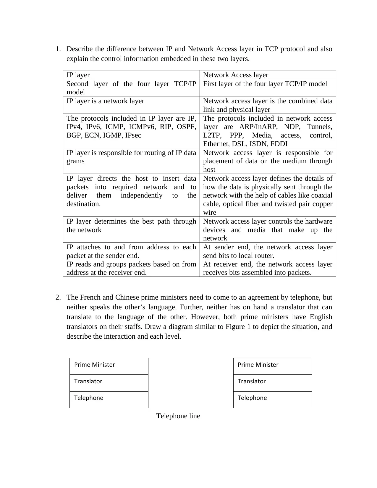
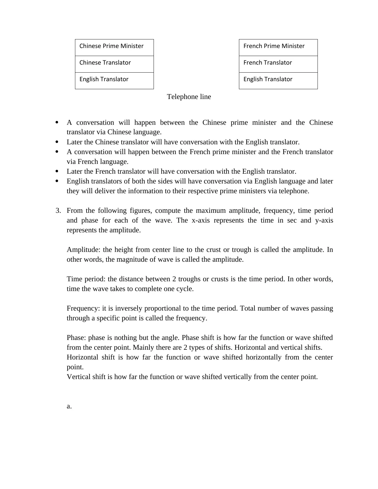
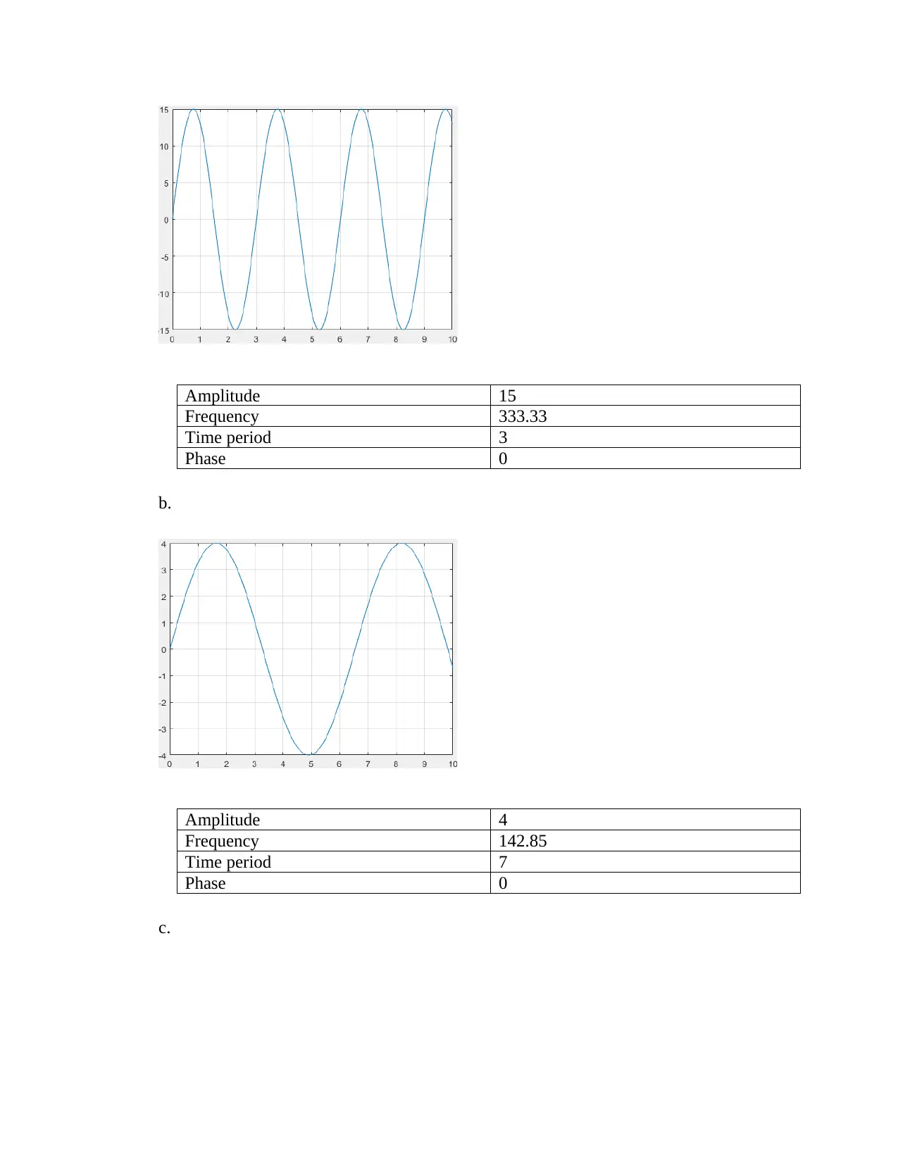
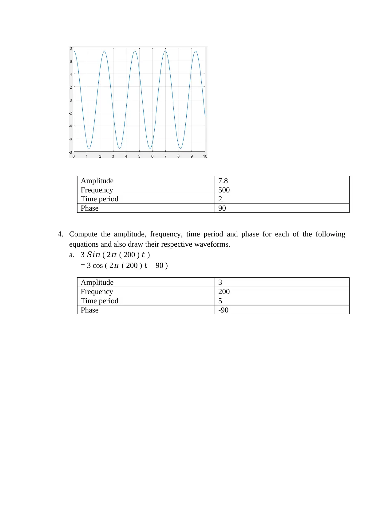
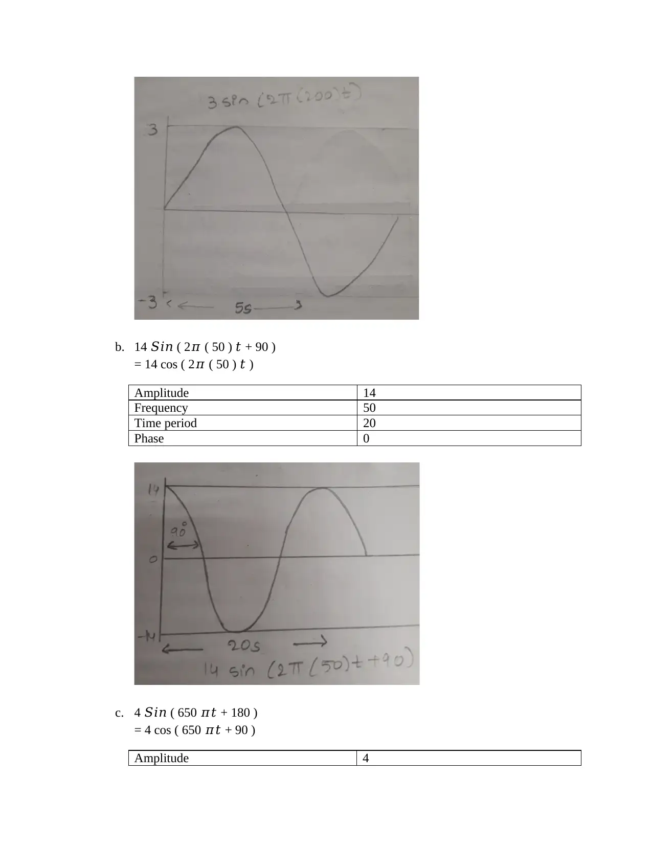
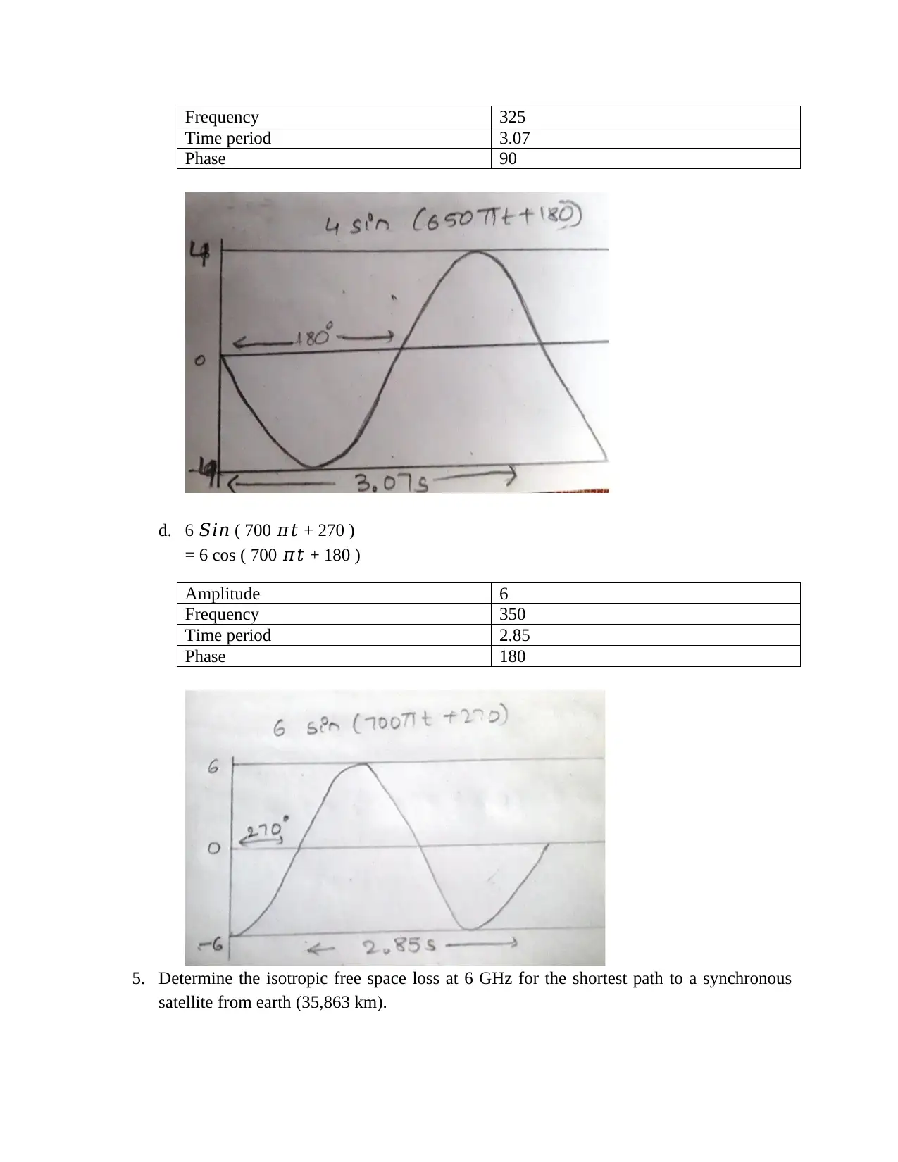
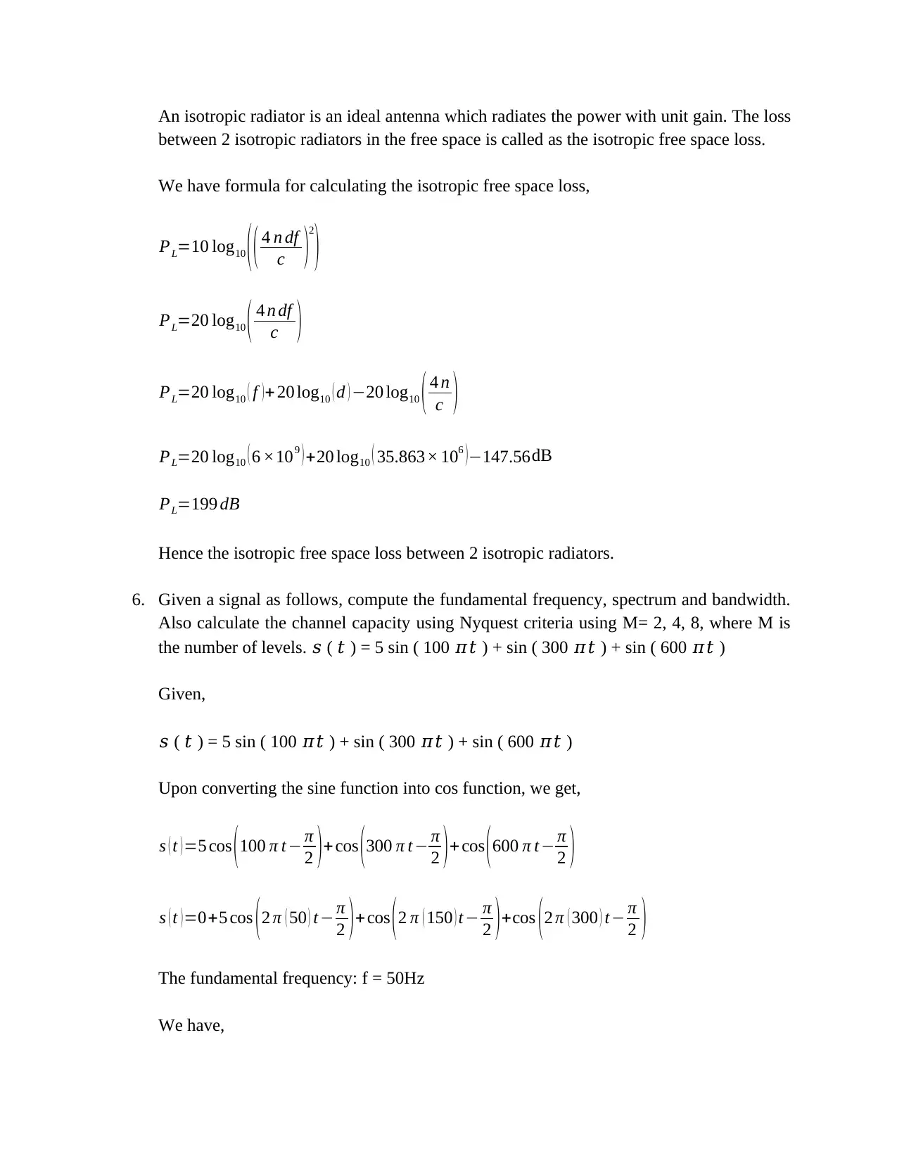
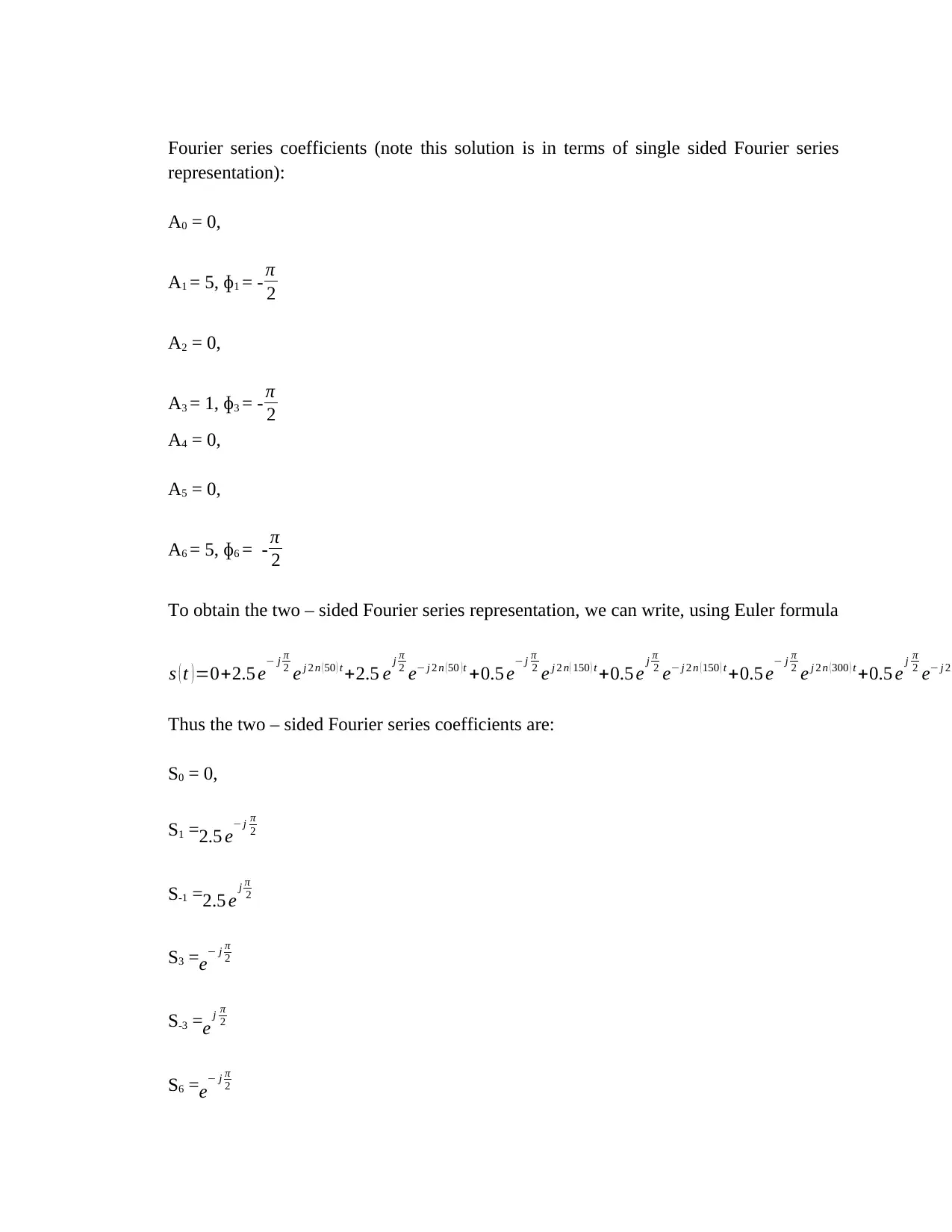
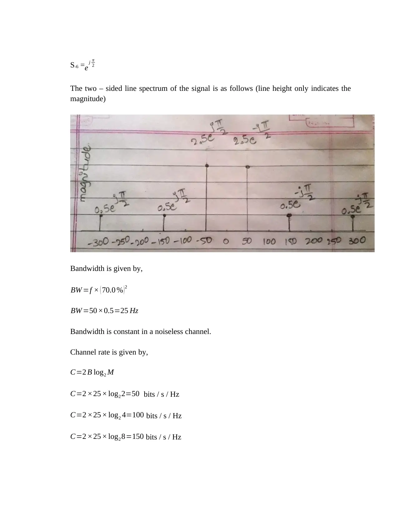
This document provides comprehensive solutions for MITS5003 Assignment 1 on Wireless Networks and Communication. It begins by differentiating between the IP and Network Access layers in the TCP/IP model, detailing the control information embedded within each layer. The solution then addresses a communication scenario between the French and Chinese prime ministers, illustrating the interaction using a diagram and explaining the role of translators. Further, it includes the computation of amplitude, frequency, time period, and phase for several waveforms and equations, with accompanying waveforms. The document also calculates the isotropic free space loss at 6 GHz, and analyzes a given signal to determine its fundamental frequency, spectrum, bandwidth, and channel capacity using the Nyquist criteria. The solution also explains methods to increase the data rate over a channel without increasing bandwidth, discussing the disadvantages of such methods. Finally, the document differentiates between packet switching and circuit switching, highlighting their advantages and disadvantages. This assignment provides a detailed understanding of various concepts in wireless networks and communication.

Prime Minister
Translator
Telephone Telephone
Translator
Prime Minister
1. Describe the difference between IP and Network Access layer in TCP protocol and also
explain the control information embedded in these two layers.
IP layer Network Access layer
Second layer of the four layer TCP/IP
model
First layer of the four layer TCP/IP model
IP layer is a network layer Network access layer is the combined data
link and physical layer
The protocols included in IP layer are IP,
IPv4, IPv6, ICMP, ICMPv6, RIP, OSPF,
BGP, ECN, IGMP, IPsec
The protocols included in network access
layer are ARP/InARP, NDP, Tunnels,
L2TP, PPP, Media, access, control,
Ethernet, DSL, ISDN, FDDI
IP layer is responsible for routing of IP data
grams
Network access layer is responsible for
placement of data on the medium through
host
IP layer directs the host to insert data
packets into required network and to
deliver them independently to the
destination.
Network access layer defines the details of
how the data is physically sent through the
network with the help of cables like coaxial
cable, optical fiber and twisted pair copper
wire
IP layer determines the best path through
the network
Network access layer controls the hardware
devices and media that make up the
network
IP attaches to and from address to each
packet at the sender end.
IP reads and groups packets based on from
address at the receiver end.
At sender end, the network access layer
send bits to local router.
At receiver end, the network access layer
receives bits assembled into packets.
2. The French and Chinese prime ministers need to come to an agreement by telephone, but
neither speaks the other’s language. Further, neither has on hand a translator that can
translate to the language of the other. However, both prime ministers have English
translators on their staffs. Draw a diagram similar to Figure 1 to depict the situation, and
describe the interaction and each level.
Telephone line
Translator
Telephone Telephone
Translator
Prime Minister
1. Describe the difference between IP and Network Access layer in TCP protocol and also
explain the control information embedded in these two layers.
IP layer Network Access layer
Second layer of the four layer TCP/IP
model
First layer of the four layer TCP/IP model
IP layer is a network layer Network access layer is the combined data
link and physical layer
The protocols included in IP layer are IP,
IPv4, IPv6, ICMP, ICMPv6, RIP, OSPF,
BGP, ECN, IGMP, IPsec
The protocols included in network access
layer are ARP/InARP, NDP, Tunnels,
L2TP, PPP, Media, access, control,
Ethernet, DSL, ISDN, FDDI
IP layer is responsible for routing of IP data
grams
Network access layer is responsible for
placement of data on the medium through
host
IP layer directs the host to insert data
packets into required network and to
deliver them independently to the
destination.
Network access layer defines the details of
how the data is physically sent through the
network with the help of cables like coaxial
cable, optical fiber and twisted pair copper
wire
IP layer determines the best path through
the network
Network access layer controls the hardware
devices and media that make up the
network
IP attaches to and from address to each
packet at the sender end.
IP reads and groups packets based on from
address at the receiver end.
At sender end, the network access layer
send bits to local router.
At receiver end, the network access layer
receives bits assembled into packets.
2. The French and Chinese prime ministers need to come to an agreement by telephone, but
neither speaks the other’s language. Further, neither has on hand a translator that can
translate to the language of the other. However, both prime ministers have English
translators on their staffs. Draw a diagram similar to Figure 1 to depict the situation, and
describe the interaction and each level.
Telephone line
Paraphrase This Document
Need a fresh take? Get an instant paraphrase of this document with our AI Paraphraser

Chinese Prime Minister
Chinese Translator
English Translator English Translator
French Translator
French Prime Minister
Telephone line
A conversation will happen between the Chinese prime minister and the Chinese
translator via Chinese language.
Later the Chinese translator will have conversation with the English translator.
A conversation will happen between the French prime minister and the French translator
via French language.
Later the French translator will have conversation with the English translator.
English translators of both the sides will have conversation via English language and later
they will deliver the information to their respective prime ministers via telephone.
3. From the following figures, compute the maximum amplitude, frequency, time period
and phase for each of the wave. The x-axis represents the time in sec and y-axis
represents the amplitude.
Amplitude: the height from center line to the crust or trough is called the amplitude. In
other words, the magnitude of wave is called the amplitude.
Time period: the distance between 2 troughs or crusts is the time period. In other words,
time the wave takes to complete one cycle.
Frequency: it is inversely proportional to the time period. Total number of waves passing
through a specific point is called the frequency.
Phase: phase is nothing but the angle. Phase shift is how far the function or wave shifted
from the center point. Mainly there are 2 types of shifts. Horizontal and vertical shifts.
Horizontal shift is how far the function or wave shifted horizontally from the center
point.
Vertical shift is how far the function or wave shifted vertically from the center point.
a.

Amplitude 15
Frequency 333.33
Time period 3
Phase 0
b.
Amplitude 4
Frequency 142.85
Time period 7
Phase 0
c.
Frequency 333.33
Time period 3
Phase 0
b.
Amplitude 4
Frequency 142.85
Time period 7
Phase 0
c.
You're viewing a preview
Unlock full access by subscribing today!

Amplitude 7.8
Frequency 500
Time period 2
Phase 90
4. Compute the amplitude, frequency, time period and phase for each of the following
equations and also draw their respective waveforms.
a. 3 𝑆𝑖𝑛 ( 2𝜋 ( 200 ) 𝑡 )
= 3 cos ( 2𝜋 ( 200 ) 𝑡 – 90 )
Amplitude 3
Frequency 200
Time period 5
Phase -90
Frequency 500
Time period 2
Phase 90
4. Compute the amplitude, frequency, time period and phase for each of the following
equations and also draw their respective waveforms.
a. 3 𝑆𝑖𝑛 ( 2𝜋 ( 200 ) 𝑡 )
= 3 cos ( 2𝜋 ( 200 ) 𝑡 – 90 )
Amplitude 3
Frequency 200
Time period 5
Phase -90
Paraphrase This Document
Need a fresh take? Get an instant paraphrase of this document with our AI Paraphraser

b. 14 𝑆𝑖𝑛 ( 2𝜋 ( 50 ) 𝑡 + 90 )
= 14 cos ( 2𝜋 ( 50 ) 𝑡 )
Amplitude 14
Frequency 50
Time period 20
Phase 0
c. 4 𝑆𝑖𝑛 ( 650 𝜋𝑡 + 180 )
= 4 cos ( 650 𝜋𝑡 + 90 )
Amplitude 4
= 14 cos ( 2𝜋 ( 50 ) 𝑡 )
Amplitude 14
Frequency 50
Time period 20
Phase 0
c. 4 𝑆𝑖𝑛 ( 650 𝜋𝑡 + 180 )
= 4 cos ( 650 𝜋𝑡 + 90 )
Amplitude 4

Frequency 325
Time period 3.07
Phase 90
d. 6 𝑆𝑖𝑛 ( 700 𝜋𝑡 + 270 )
= 6 cos ( 700 𝜋𝑡 + 180 )
Amplitude 6
Frequency 350
Time period 2.85
Phase 180
5. Determine the isotropic free space loss at 6 GHz for the shortest path to a synchronous
satellite from earth (35,863 km).
Time period 3.07
Phase 90
d. 6 𝑆𝑖𝑛 ( 700 𝜋𝑡 + 270 )
= 6 cos ( 700 𝜋𝑡 + 180 )
Amplitude 6
Frequency 350
Time period 2.85
Phase 180
5. Determine the isotropic free space loss at 6 GHz for the shortest path to a synchronous
satellite from earth (35,863 km).
You're viewing a preview
Unlock full access by subscribing today!

An isotropic radiator is an ideal antenna which radiates the power with unit gain. The loss
between 2 isotropic radiators in the free space is called as the isotropic free space loss.
We have formula for calculating the isotropic free space loss,
PL=10 log10 ( ( 4 ᴨ df
c )2
)
PL=20 log10 ( 4 ᴨ df
c )
PL=20 log10 ( f )+ 20 log10 ( d ) −20 log10 ( 4 ᴨ
c )
PL=20 log10 ( 6 ×10⁹ ) +20 log10 ( 35.863× 10⁶ )−147.56dB
PL=199 dB
Hence the isotropic free space loss between 2 isotropic radiators.
6. Given a signal as follows, compute the fundamental frequency, spectrum and bandwidth.
Also calculate the channel capacity using Nyquest criteria using M= 2, 4, 8, where M is
the number of levels. 𝑠 ( 𝑡 ) = 5 sin ( 100 𝜋𝑡 ) + sin ( 300 𝜋𝑡 ) + sin ( 600 𝜋𝑡 )
Given,
𝑠 ( 𝑡 ) = 5 sin ( 100 𝜋𝑡 ) + sin ( 300 𝜋𝑡 ) + sin ( 600 𝜋𝑡 )
Upon converting the sine function into cos function, we get,
s ( t )=5 cos (100 π t− π
2 )+ cos (300 π t − π
2 )+ cos (600 π t− π
2 )
s ( t ) =0+5 cos ( 2 π ( 50 ) t− π
2 ) +cos ( 2 π ( 150 ) t− π
2 ) +cos ( 2 π ( 300 ) t− π
2 )
The fundamental frequency: f = 50Hz
We have,
Paraphrase This Document
Need a fresh take? Get an instant paraphrase of this document with our AI Paraphraser

Fourier series coefficients (note this solution is in terms of single sided Fourier series
representation):
A0 = 0,
A1 = 5, ɸ1 = - π
2
A2 = 0,
A3 = 1, ɸ3 = - π
2
A4 = 0,
A5 = 0,
A6 = 5, ɸ6 = - π
2
To obtain the two – sided Fourier series representation, we can write, using Euler formula
s ( t ) =0+2.5 e− j π
2 e j 2 ᴨ ( 50 ) t +2.5 e j π
2 e− j 2 ᴨ ( 50 ) t +0.5 e− j π
2 e j 2 ᴨ ( 150 ) t +0.5 e j π
2 e− j 2 ᴨ ( 150 ) t +0.5 e− j π
2 e j 2 ᴨ ( 300 ) t +0.5 e j π
2 e− j 2
Thus the two – sided Fourier series coefficients are:
S0 = 0,
S1 =2.5 e− j π
2
S-1 =2.5 e j π
2
S3 =e− j π
2
S-3 =e j π
2
S6 =e− j π
2

S-6 =e j π
2
The two – sided line spectrum of the signal is as follows (line height only indicates the
magnitude)
Bandwidth is given by,
BW =f × ( 70.0 % )2
BW =50 ×0.5=25 Hz
Bandwidth is constant in a noiseless channel.
Channel rate is given by,
C=2 B log2 M
C=2 ×25 × log2 2=50 bits / s / Hz
C=2 ×25 × log2 4=100 bits / s / Hz
C=2 ×25 × log2 8=150 bits / s / Hz
You're viewing a preview
Unlock full access by subscribing today!

7. Explain how the data rate over a channel can be increased, without increasing the
bandwidth? What is the disadvantage of this approach? Hint : Nyquist Theorem
Nyquist gives the upper bound for the bit rate of a transmission system by calculating the
bit rate directly from the number of bits in a symbol (or signal levels) and the bandwidth
of the system (assuming 2 symbols/per cycle and first harmonic).
Increasing the levels of a signal increases the probability of an error occurring, in other
words it reduces the reliability of the system.
The bit rate of a system increases with an increase in the number of signal levels we
use to denote a symbol.
A symbol can consist of a single bit or “n” bits.
The number of signal levels = 2n.
As the number of levels goes up, the spacing between level decreases -> increasing
the probability of an error occurring in the presence of transmission impairments.
Nyquist gives the upper bound for the bit rate of a transmission system by calculating
the bit rate directly from the number of bits in a symbol (or signal levels) and the
bandwidth of the system (assuming 2 symbols/per cycle and first harmonic).
Nyquist theorem states that for a noiseless channel:
C = 2 B log22n
C= capacity in bps
B = bandwidth in Hz
Aliasing is a method using which the data rate over a channel can be increased without
increasing the bandwidth. Aliasing can make 2 different signals look alike by limiting the
bandwidth. In other words, aliasing folds the higher frequency signals to appear as lower
frequency signal. But, the disadvantage of this approach is that, the signals are not
properly reconstructed at the receiver side, meaning low quality signals get reproduced.
8. What is the main difference between Packet switching and Circuit Switching? Also
discuss the advantages of Packet switching over Circuit Switching and vice versa.
Circuit switching Packet switching
There is a dedicated transmission path There is no such dedicated path
Information is not saved Packets will be stored until they get
delivered
Delay will be mainly call setup delay Delay will be mainly packet transmission
delay
Overload blocks the call Overload increases the packet delay
Path is fixed for the entire conversation Each data packet may choose different
Paraphrase This Document
Need a fresh take? Get an instant paraphrase of this document with our AI Paraphraser

paths
Transmission of continuous data takes
place
Transmission of data packets takes place
Big sized switching nodes are used Small sized switching nodes are used
There will no overhead bits once the call is
setup
There will be overhead of bits in each
packet
Responsibility of message loss will be of
user, in other words, user will be
responsible for message loss
Responsibility of packet sequences will be
of network, in other words, network will be
responsible for the packet sequence
The circuit switching uses fixed bandwidth,
in other words, the bandwidth is reserved
before the transmission starts
The packet switching uses dynamic
bandwidth, in other words, the bandwidth
usage takes place in hand to hand with the
transmission
Circuit switching is physical Packet switching is not physical
Connection will be lost, if any one of the
link connecting both the ends gets broken.
Connection could continue if any one of
the route breaks, as the host can choose
other routes.
Same route will be chosen for information
delivery between the hosts
Different routes could be chosen for
information delivery between the hosts
Always the information arrives the
destination in order.
Not always the information arrives the
destination in order.
Congestion is call based Congestion is packet based
Utilization of bandwidth is partial Utilization of bandwidth is full
Store and forward transmission technique
is not used
Store and forward transmission technique
is used
Circuit switching is transparent Packet switching is not transparent
Cost is based on time consumption Cost is based on number of packets utilized
End terminals are telephone and modem End terminals are computers
Information type being used are analog
voice or PCM digital voice
Information being used is binary
information (0’s and 1’s)
Transmission system being used is analog
and digital data over different transmission
media
Transmission system being used is digital
data over different transmission media
Advantages of packet switching over
circuit switching
Advantages of circuit switching over
packet switching
As in case of packet switching the entire
bandwidth is not reserved, at the end of
transmission, there won’t be any wastage
of bandwidth, whereas in case of circuit
switching, the entire bandwidth is reserved
in advance and there occurs wastage of
bandwidth, if not fully consumed.
In case of circuit switching, the information
arrives in order at destination, which makes
this switching more organized when
compared to the packet switching, where
the information doesn’t arrive in order.
As in case of packet switching, even if one
of the links breaks, the packets choose
In case of circuit switching, the
transmission / communication is

different route for transmission purpose,
therefore the communication doesn’t get
disturbed, whereas in case of circuit
switching, as the information moves
through single path, if it gets broken, then
the whole communication gets disturbed.
transparent, whereas in case of packet
switching, there will be no transparency,
which makes circuit switching more
reliable.
Store and forward transmission in packet
switching helps to store the information,
whereas in case of circuit switching, the
store and forward transmission is not used.
In case of circuit switching, the
transmission is transparent, the error
checking becomes easier, whereas, in case
of packet switching, the transmission is not
transparent.
The end terminals being computers in case
of packet switching makes it easier to
check for the information, whereas in case
of circuit switching, the end terminals are
telephone and modems.
As the path is fixed / conserved for the
entire transmission, the reason for delay
can be known, but in case of packet
switching, the path is different for different
packets, in other words, the packets choose
the path for themselves.
9. In a LOS communication, consider d = 60 km, the requirement is to make two antennas
(transmitter and receiver) such that the height of one antenna should be four time of the
other. Considering this, find the appropriate heights of these two antennas.
The formula for calculating the distance between 2 antennas in a Line Of Sight
communication is given by,
d=3.57 √ K h
d=3.57 ¿
We have K= 4
3
d=4.12( √ hT + √ 4 hT ) As per given condition
d=4.12 ×3 √ hT
d=12.36 √ hT
60=12.36 √hT
hT =23.56 m
You're viewing a preview
Unlock full access by subscribing today!

hR=4 × 23.56=94.25 m
References:
Giangrandi, I. (2019). Isotropic loss of free-space radiation. [online] Giangrandi.ch.
Available at: http://www.giangrandi.ch/electronics/anttool/iso-loss.shtml
System, O., Mohan, R., yousif, y., apake, A., Banda, A., Karr, W., yejashwi, k. and
Vaghani, N. (2019). Difference Between Circuit Switching and Packet Switching (with
Comparison Chart)- Tech Differences. [online] Tech Differences. Available at:
https://techdifferences.com/difference-between-circuit-switching-and-packet-
switching.html
1 out of 13
Related Documents

Your All-in-One AI-Powered Toolkit for Academic Success.
+13062052269
info@desklib.com
Available 24*7 on WhatsApp / Email
Unlock your academic potential
© 2024 | Zucol Services PVT LTD | All rights reserved.