MITS5003 Wireless Networks & Communication Assignment 2 Analysis

Verified

Added on  2022/09/28

|9
|933
|32
Homework Assignment
AI Summary
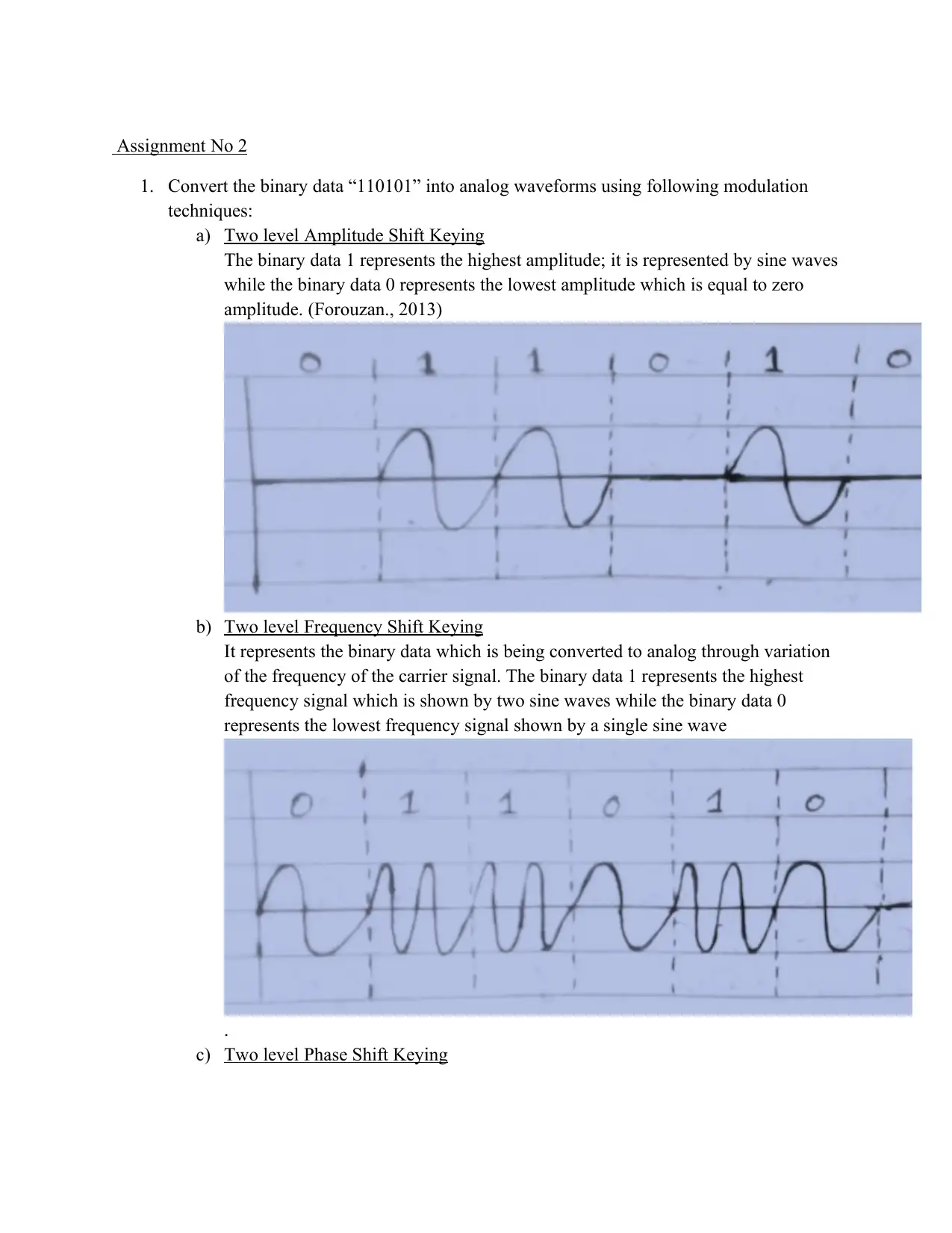
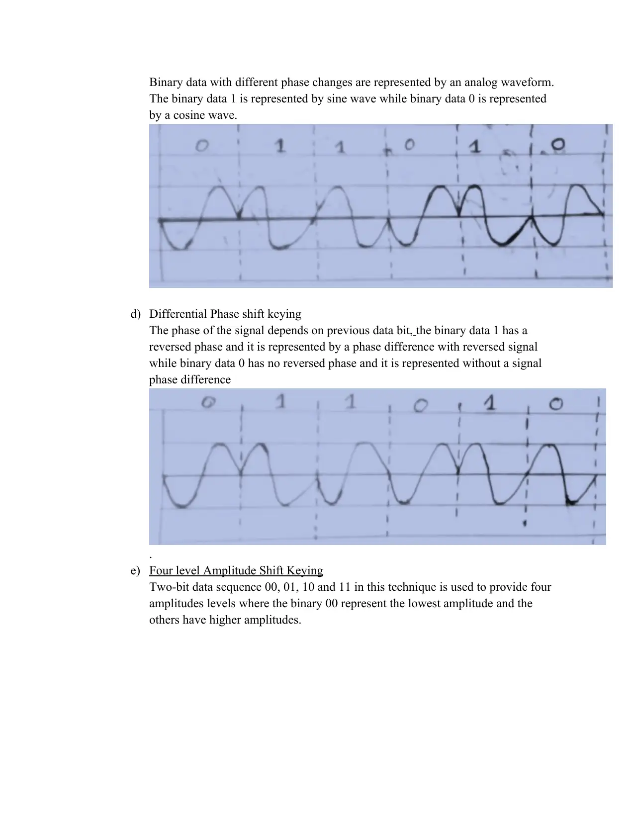
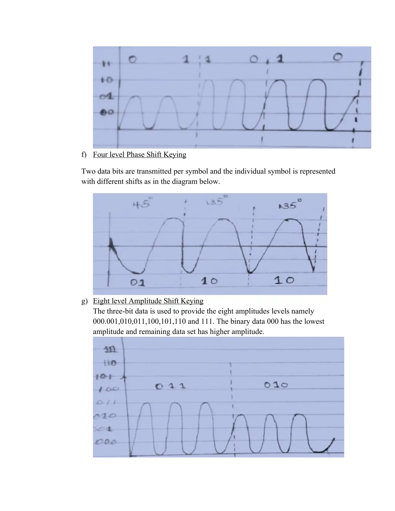
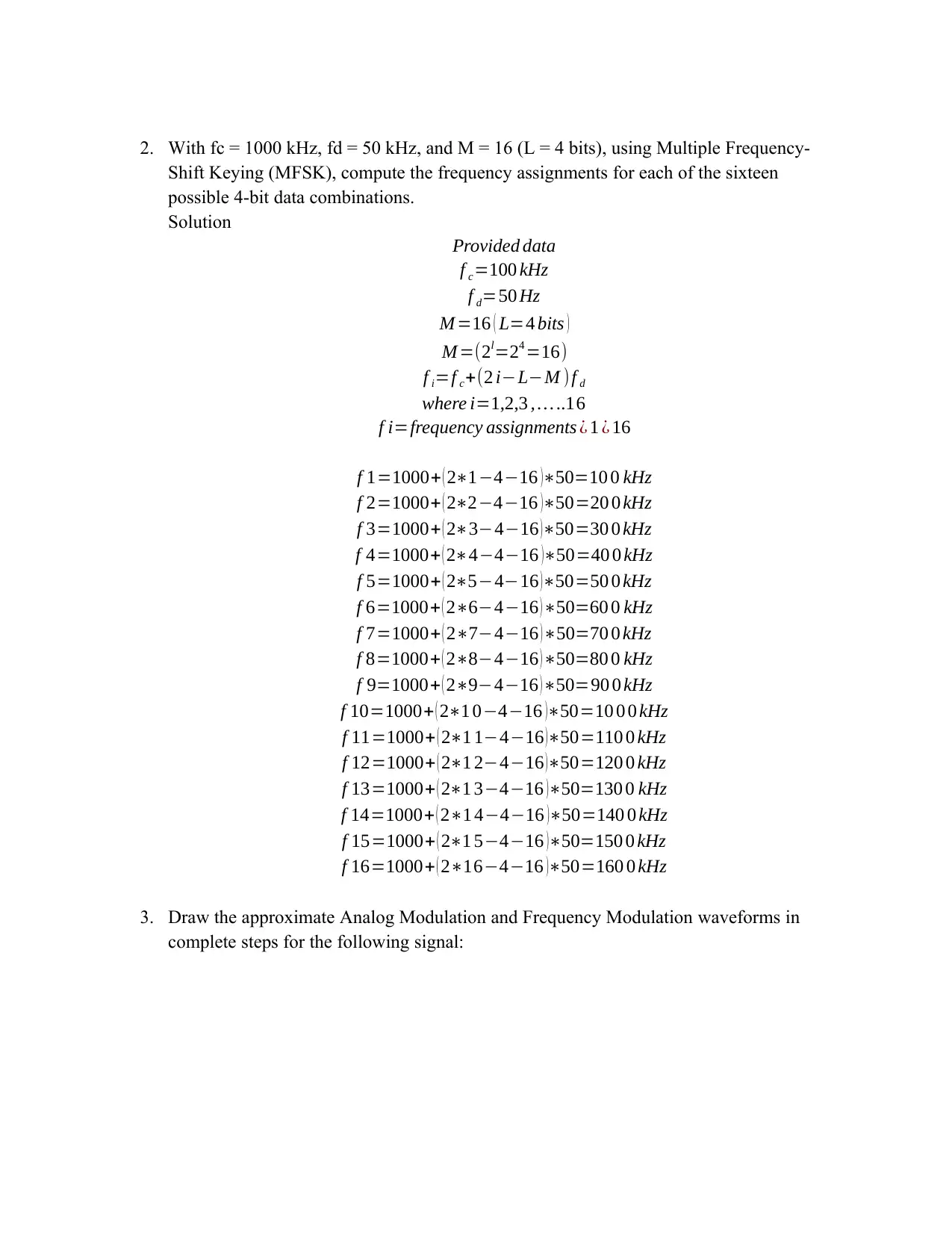
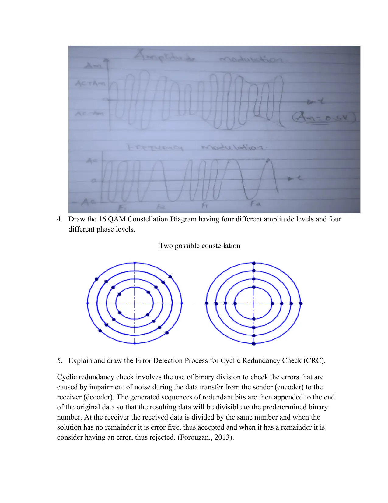
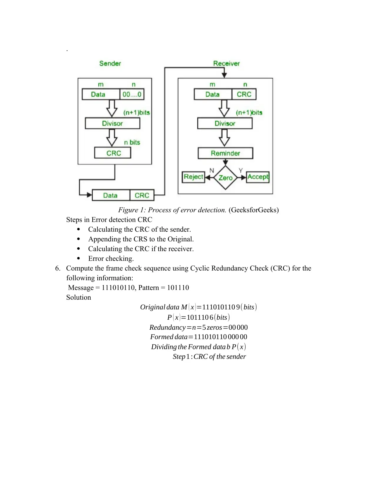
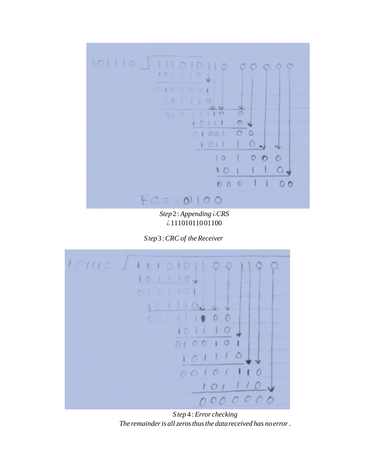
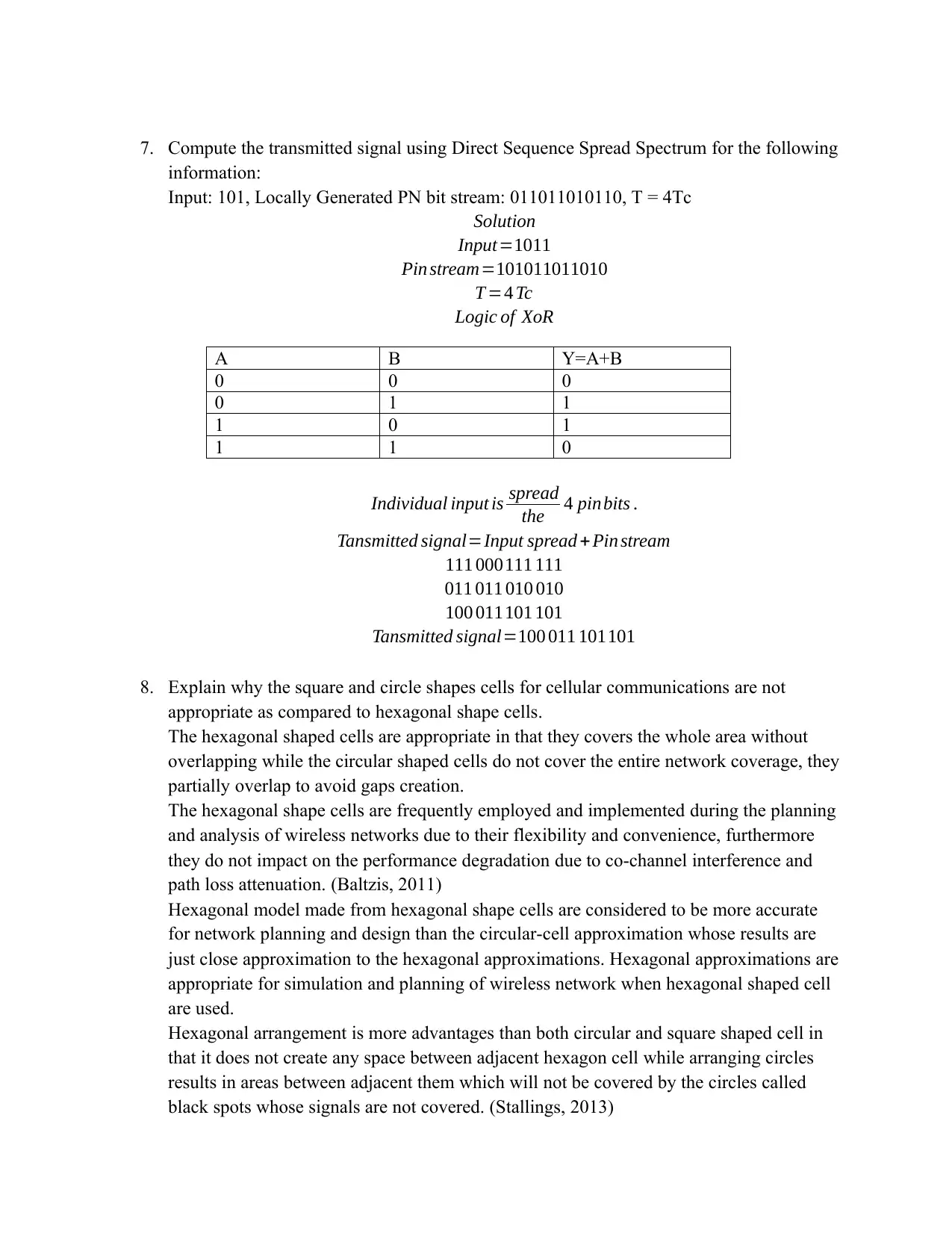
This assignment solution for MITS5003, a Wireless Networks and Communication course, addresses various aspects of wireless communication systems. It begins by converting binary data into analog waveforms using different modulation techniques such as Two-level Amplitude Shift Keying, Frequency Shift Keying, Phase Shift Keying and Differential Phase Shift Keying. Further, it computes frequency assignments for MFSK, draws a 16 QAM constellation diagram, and explains the error detection process using Cyclic Redundancy Check (CRC), including the steps involved and a practical example. The solution also computes the transmitted signal using Direct Sequence Spread Spectrum. Finally, it explains the advantages of hexagonal cell shapes over circular and square shapes in cellular communications. The assignment uses concepts from the provided references and covers multiple areas in wireless communication systems.
tabler-icon-diamond-filled.svg

Contribute Materials

Your contribution can guide someone’s learning journey. Share your documents today.
Document Page
Assignment No 2
1. Convert the binary data “110101” into analog waveforms using following modulation
techniques:
a) Two level Amplitude Shift Keying
The binary data 1 represents the highest amplitude; it is represented by sine waves
while the binary data 0 represents the lowest amplitude which is equal to zero
amplitude. (Forouzan., 2013)
b) Two level Frequency Shift Keying
It represents the binary data which is being converted to analog through variation
of the frequency of the carrier signal. The binary data 1 represents the highest
frequency signal which is shown by two sine waves while the binary data 0
represents the lowest frequency signal shown by a single sine wave
.
c) Two level Phase Shift Keying
tabler-icon-diamond-filled.svg

Secure Best Marks with AI Grader

Need help grading? Try our AI Grader for instant feedback on your assignments.
Document Page
Binary data with different phase changes are represented by an analog waveform.
The binary data 1 is represented by sine wave while binary data 0 is represented
by a cosine wave.
d) Differential Phase shift keying
The phase of the signal depends on previous data bit, the binary data 1 has a
reversed phase and it is represented by a phase difference with reversed signal
while binary data 0 has no reversed phase and it is represented without a signal
phase difference
.
e) Four level Amplitude Shift Keying
Two-bit data sequence 00, 01, 10 and 11 in this technique is used to provide four
amplitudes levels where the binary 00 represent the lowest amplitude and the
others have higher amplitudes.
Document Page
f) Four level Phase Shift Keying
Two data bits are transmitted per symbol and the individual symbol is represented
with different shifts as in the diagram below.
g) Eight level Amplitude Shift Keying
The three-bit data is used to provide the eight amplitudes levels namely
000.001,010,011,100,101,110 and 111. The binary data 000 has the lowest
amplitude and remaining data set has higher amplitude.
Document Page
2. With fc = 1000 kHz, fd = 50 kHz, and M = 16 (L = 4 bits), using Multiple Frequency-
Shift Keying (MFSK), compute the frequency assignments for each of the sixteen
possible 4-bit data combinations.
Solution
Provided data
f c=100 kHz
f d=50 Hz
M =16 ( L=4 bits )
M =(2l=24 =16)
f i=f c+(2 iLM ) f d
where i=1,2,3 , ..16
f i=frequency assignments ¿ 1 ¿ 16
f 1=1000+ ( 21416 )50=10 0 kHz
f 2=1000+ ( 22416 )50=20 0 kHz
f 3=1000+ ( 23416 )50=30 0 kHz
f 4=1000+ ( 24416 )50=40 0 kHz
f 5=1000+ ( 25416 )50=50 0 kHz
f 6=1000+ ( 26416 ) 50=60 0 kHz
f 7=1000+ ( 27416 ) 50=70 0 kHz
f 8=1000+ ( 28416 ) 50=80 0 kHz
f 9=1000+ ( 29416 )50=90 0 kHz
f 10=1000+ ( 21 0416 )50=10 0 0 kHz
f 11=1000+ ( 21 1416 )50=110 0 kHz
f 12=1000+ ( 21 2416 )50=120 0 kHz
f 13=1000+ ( 21 3416 )50=130 0 kHz
f 14=1000+ ( 21 4416 )50=140 0 kHz
f 15=1000+ ( 21 5416 )50=150 0 kHz
f 16=1000+ ( 216416 )50=160 0 kHz
3. Draw the approximate Analog Modulation and Frequency Modulation waveforms in
complete steps for the following signal:
tabler-icon-diamond-filled.svg

Secure Best Marks with AI Grader

Need help grading? Try our AI Grader for instant feedback on your assignments.
Document Page
4. Draw the 16 QAM Constellation Diagram having four different amplitude levels and four
different phase levels.
Two possible constellation
5. Explain and draw the Error Detection Process for Cyclic Redundancy Check (CRC).
Cyclic redundancy check involves the use of binary division to check the errors that are
caused by impairment of noise during the data transfer from the sender (encoder) to the
receiver (decoder). The generated sequences of redundant bits are then appended to the end
of the original data so that the resulting data will be divisible to the predetermined binary
number. At the receiver the received data is divided by the same number and when the
solution has no remainder it is error free, thus accepted and when it has a remainder it is
consider having an error, thus rejected. (Forouzan., 2013).
Document Page
.
Figure 1: Process of error detection. (GeeksforGeeks)
Steps in Error detection CRC
Calculating the CRC of the sender.
Appending the CRS to the Original.
Calculating the CRC if the receiver.
Error checking.
6. Compute the frame check sequence using Cyclic Redundancy Check (CRC) for the
following information:
Message = 111010110, Pattern = 101110
Solution
Original data M ( x ) =111010110 9( bits)
P ( x ) =101110 6(bits)
Redundancy=n=5 zeros=00 000
Formed data=111010110 000 00
Dividing the Formed data b P(x)
Step 1 :CRC of the sender
Document Page
Step2 : Appending ¿CRS
¿ 111010110 01100
S tep 3 :CRC of the Receiver
S tep 4 : Error checking
The remainder is all zeros thus the data received has no error .
tabler-icon-diamond-filled.svg

Paraphrase This Document

Need a fresh take? Get an instant paraphrase of this document with our AI Paraphraser
Document Page
7. Compute the transmitted signal using Direct Sequence Spread Spectrum for the following
information:
Input: 101, Locally Generated PN bit stream: 011011010110, T = 4Tc
Solution
Input=1011
Pin stream=101011011010
T =4 Tc
Logic of XoR
A B Y=A+B
0 0 0
0 1 1
1 0 1
1 1 0
Individual input is spread
the 4 pinbits .
Tansmitted signal=Input spread +Pin stream
111 000111 111
011 011 010 010
100 011101 101
Tansmitted signal=100 011 101101
8. Explain why the square and circle shapes cells for cellular communications are not
appropriate as compared to hexagonal shape cells.
The hexagonal shaped cells are appropriate in that they covers the whole area without
overlapping while the circular shaped cells do not cover the entire network coverage, they
partially overlap to avoid gaps creation.
The hexagonal shape cells are frequently employed and implemented during the planning
and analysis of wireless networks due to their flexibility and convenience, furthermore
they do not impact on the performance degradation due to co-channel interference and
path loss attenuation. (Baltzis, 2011)
Hexagonal model made from hexagonal shape cells are considered to be more accurate
for network planning and design than the circular-cell approximation whose results are
just close approximation to the hexagonal approximations. Hexagonal approximations are
appropriate for simulation and planning of wireless network when hexagonal shaped cell
are used.
Hexagonal arrangement is more advantages than both circular and square shaped cell in
that it does not create any space between adjacent hexagon cell while arranging circles
results in areas between adjacent them which will not be covered by the circles called
black spots whose signals are not covered. (Stallings, 2013)
Document Page
References
Baltzis, K. B. (2011, April). Hexagonal vs Circular cell shape. Retrieved from A Comparison Analysis and
Evaluation of Two popular modelling Approximation:
https://www.researchgate.net/publication/221912601_Hexagonal_vs_Circular_Cell_Shape_A_C
omparative_Analysis_and_Evaluation_of_the_Two_Popular_Modeling_Approximations
Forouzan., B. (2013). Data Communications and Networking.5th edition. McGraw Hill.
GeeksforGeeks. (n.d.). Error Detection in Computer Networks. Retrieved from A Computer science portal
fro geeks: https://www.geeksforgeeks.org/error-detection-in-computer-networks/
Stallings, W. (2013). Data and Computer Communications. Pearson.
chevron_up_icon
1 out of 9
circle_padding
hide_on_mobile
zoom_out_icon
logo.png

Your All-in-One AI-Powered Toolkit for Academic Success.

Available 24*7 on WhatsApp / Email

[object Object]