MITS5003: Wireless Networks & Communication Assignment Report 2019SS
VerifiedAdded on 2022/08/23
|22
|1928
|19
Report
AI Summary
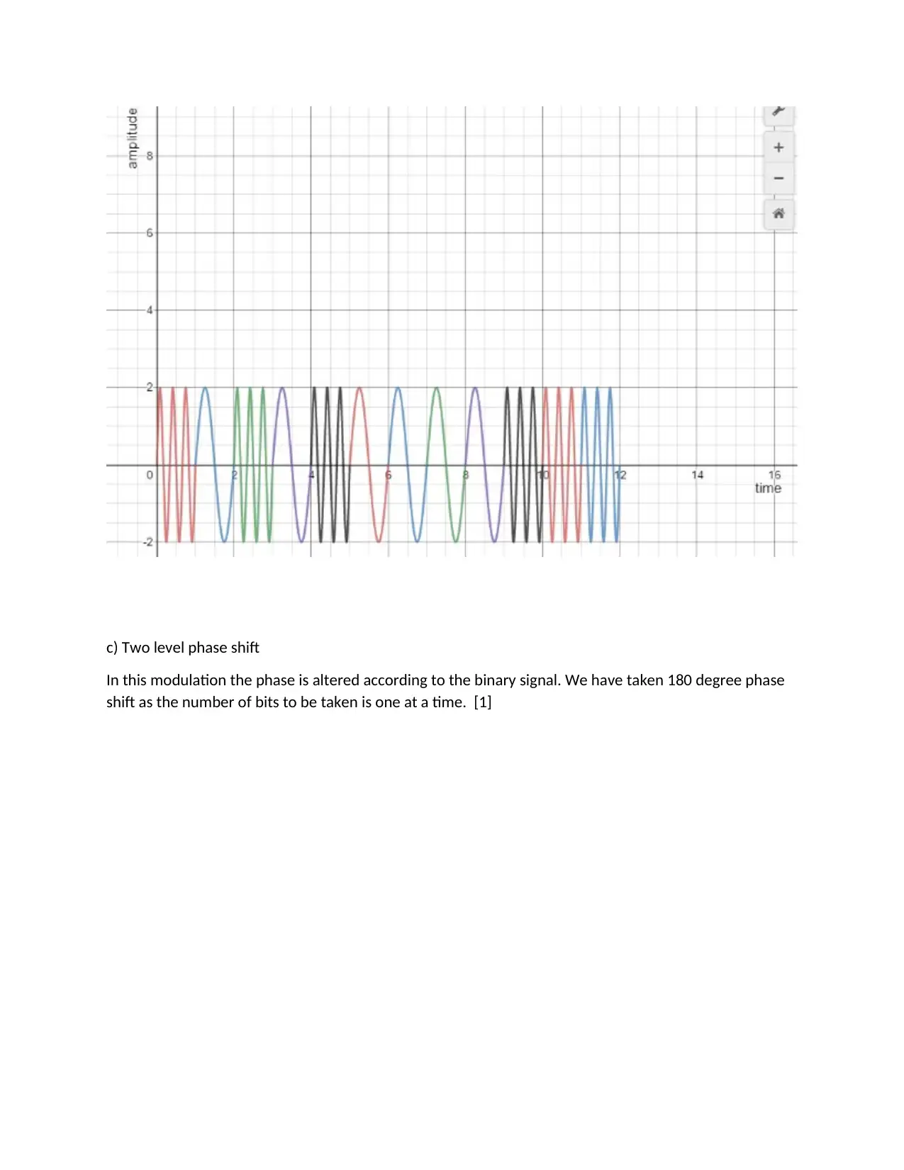
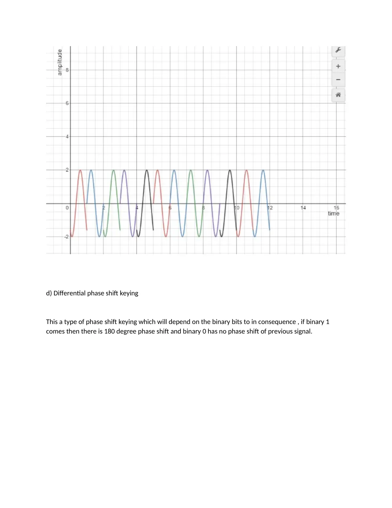
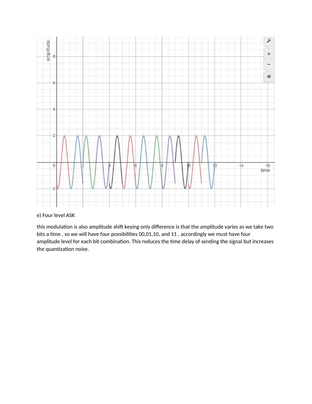
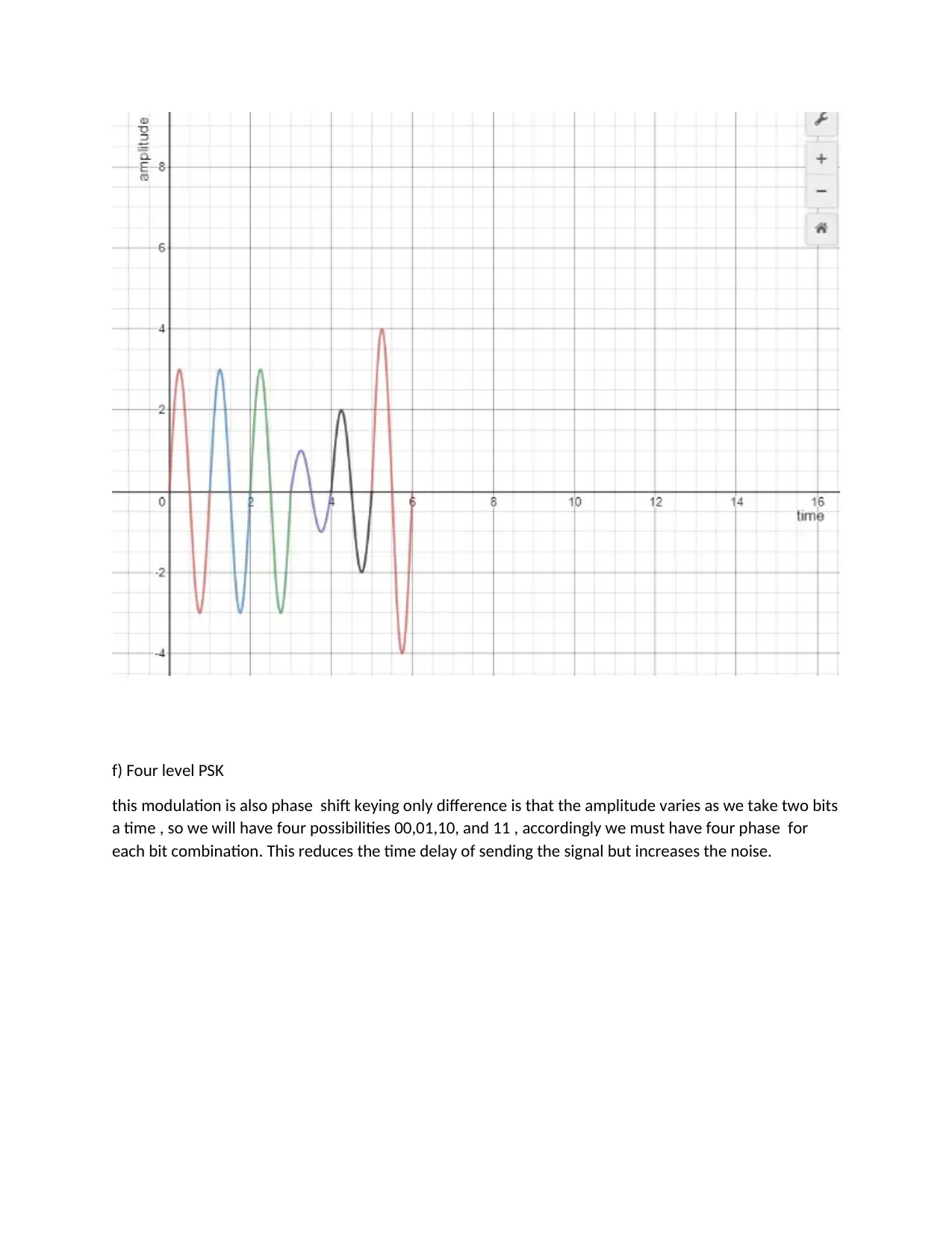
This report provides a comprehensive analysis of wireless networks and communication, covering various aspects such as data representation, signal delay calculations, and MFSK frequency calculations. It delves into amplitude and frequency modulation techniques, including their equations and waveforms, and explains constellation diagrams of 8 QAM. The report also explores mobile communication handoff strategies, CRC calculation for error detection, traffic calculations, and the cell concept in mobile communication. Each section includes detailed explanations, mathematical calculations, and relevant figures to illustrate the concepts. The report concludes with a summary of the key findings and references to support the analysis.

Wireless Networks & Communication
MITS5003
SUFI
MITS5003
SUFI
Paraphrase This Document
Need a fresh take? Get an instant paraphrase of this document with our AI Paraphraser

Contents
1. Data: 101010000111 analog waveform...................................................................................................3
2. Signal delay calculation [1]...................................................................................................................10
3. MFSK frequency calculation..................................................................................................................11
4. Amplitude and frequency Modulation [1]............................................................................................12
5. Constellation diagram of 8 QAM...........................................................................................................15
6. Mobile communication Handoff strategies[6]......................................................................................16
7. CRC calculation for error detection.......................................................................................................17
8. Traffic calculation in wireless comm......................................................................................................19
9. Cell concept in mobile communication..................................................................................................20
Conclusion.................................................................................................................................................21
References.................................................................................................................................................22

1. Data: 101010000111 analog waveform
Solution [1]
The balance of analog flag is vital strategy for remote communication because it utilizes the channel
in productive way and the message flag in computerized bits are changed into analog remote able
signals. The balance method can be classified agreeing to the parameters being shifted in analog
tweaked flag to be specific amplitude, frequency, or stage. Usually said to be sufficiency move
keying, Recurrence move keying, and stage move keying. Other half breed procedures like QAM are
moreover utilized for tweak. The tweak procedure is explained below and each one is charted for
the information given within the problem. Data: 101010000111
a) Two level ASK
The amplitude of the carrier signal is the parameter in this case where binary 0 bit has lower amplitude
and higher amplitude at binary 1
⊘ This is a preview!⊘
Do you want full access?
Subscribe today to unlock all pages.

Trusted by 1+ million students worldwide

b) Frequency shift Keying
The frequency of the carrier is lower in binary 0 bit and at binary 1 bit frequency is higher. This
classification makes it easy to distinguish at receiver and find the actual message bits.
The frequency of the carrier is lower in binary 0 bit and at binary 1 bit frequency is higher. This
classification makes it easy to distinguish at receiver and find the actual message bits.
Paraphrase This Document
Need a fresh take? Get an instant paraphrase of this document with our AI Paraphraser

c) Two level phase shift
In this modulation the phase is altered according to the binary signal. We have taken 180 degree phase
shift as the number of bits to be taken is one at a time. [1]
In this modulation the phase is altered according to the binary signal. We have taken 180 degree phase
shift as the number of bits to be taken is one at a time. [1]

d) Differential phase shift keying
This a type of phase shift keying which will depend on the binary bits to in consequence , if binary 1
comes then there is 180 degree phase shift and binary 0 has no phase shift of previous signal.
This a type of phase shift keying which will depend on the binary bits to in consequence , if binary 1
comes then there is 180 degree phase shift and binary 0 has no phase shift of previous signal.
⊘ This is a preview!⊘
Do you want full access?
Subscribe today to unlock all pages.

Trusted by 1+ million students worldwide

e) Four level ASK
this modulation is also amplitude shift keying only difference is that the amplitude varies as we take two
bits a time , so we will have four possibilities 00,01,10, and 11 , accordingly we must have four
amplitude level for each bit combination. This reduces the time delay of sending the signal but increases
the quantization noise.
Paraphrase This Document
Need a fresh take? Get an instant paraphrase of this document with our AI Paraphraser

f) Four level PSK
this modulation is also phase shift keying only difference is that the amplitude varies as we take two bits
a time , so we will have four possibilities 00,01,10, and 11 , accordingly we must have four phase for
each bit combination. This reduces the time delay of sending the signal but increases the noise.

g) 8 level ASK
this modulation is also phase shift keying only difference is that the amplitude varies as we take three
bits a time , so we will have eight possibilities 000,001,010,011,100,101,110,111 , accordingly we must
have eight amplitude for each bit combination. This reduces the time delay of sending the signal but
increases the noise.
⊘ This is a preview!⊘
Do you want full access?
Subscribe today to unlock all pages.

Trusted by 1+ million students worldwide

2. Signal delay calculation [1]
Solution: 1 us is given in the problem for sending each signal , so for calculating time delay for each
case , we use the number of bits to be sent at a time , as shown below
1. 12x1us = 12 us for Two level ASK
2. 12x1us = 12 us for Two level FSK
3. 12x1us = 12 us for Two level PSK
4. 12x1us = 12 us for DPSK
5. 6x1us = 6 us for Four level ASK
6. 6x1us = 6 us for Four level PSK
7. 4x1us = 4 us for Eight level ASK
Paraphrase This Document
Need a fresh take? Get an instant paraphrase of this document with our AI Paraphraser

3. MFSK frequency calculation
The possible frequency in MFSK is calculated by
Fi= fc+ (2i-1-M) Fd
Where FC = 1000 KHz, fd= 50 KHz, and M=16
The frequency in KHz is calculated as given in the table below
The possible frequency in MFSK is calculated by
Fi= fc+ (2i-1-M) Fd
Where FC = 1000 KHz, fd= 50 KHz, and M=16
The frequency in KHz is calculated as given in the table below

4. Amplitude and frequency Modulation [1]
The message signal’s equation for the given message waveform.
-0.5 cos (2πft), where f=1/60
The message signal’s equation for the given message waveform.
-0.5 cos (2πft), where f=1/60
⊘ This is a preview!⊘
Do you want full access?
Subscribe today to unlock all pages.

Trusted by 1+ million students worldwide
1 out of 22
Related Documents

Your All-in-One AI-Powered Toolkit for Academic Success.
+13062052269
info@desklib.com
Available 24*7 on WhatsApp / Email
Unlock your academic potential
© 2024 | Zucol Services PVT LTD | All rights reserved.