MITS5003 Wireless Networks & Communication: Term Paper Solution 2019S2

Verified

Added on  2022/10/06

|14
|821
|24
Homework Assignment
AI Summary
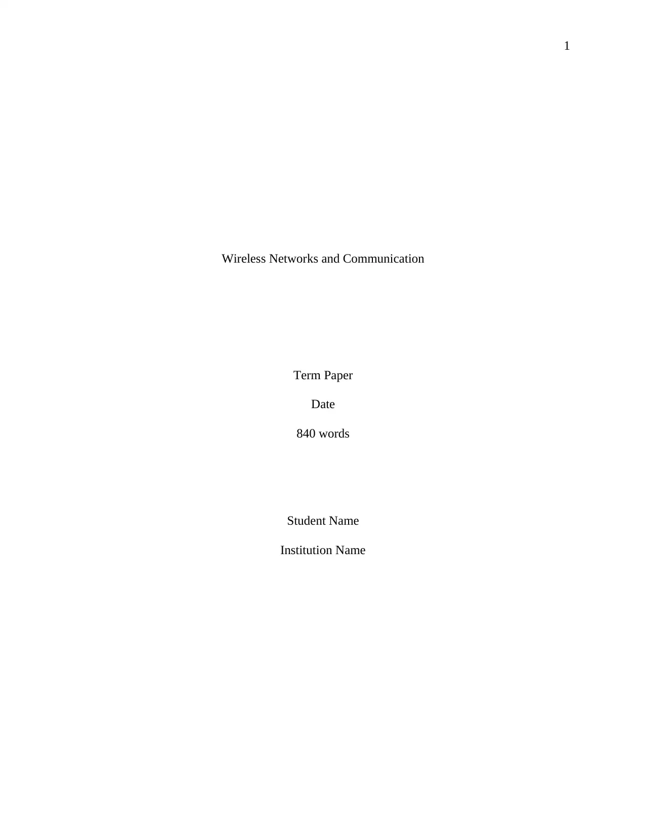
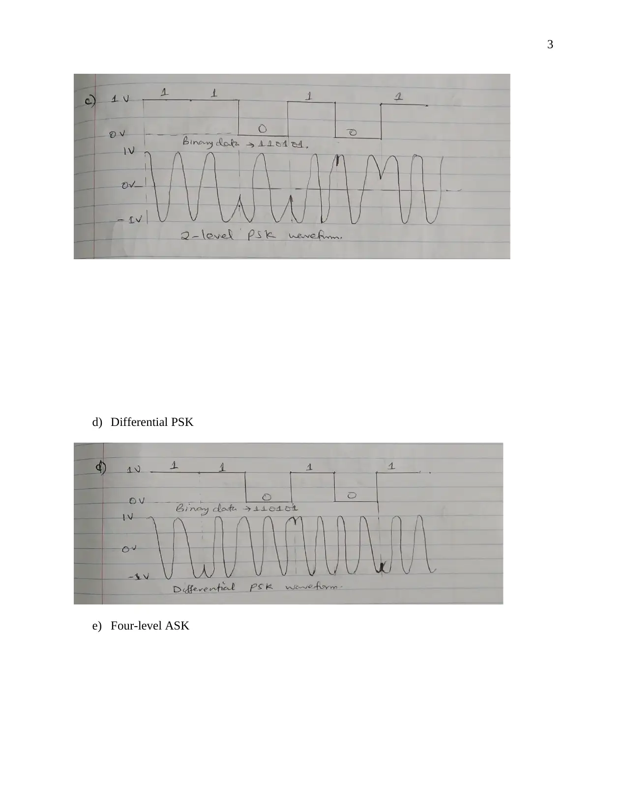
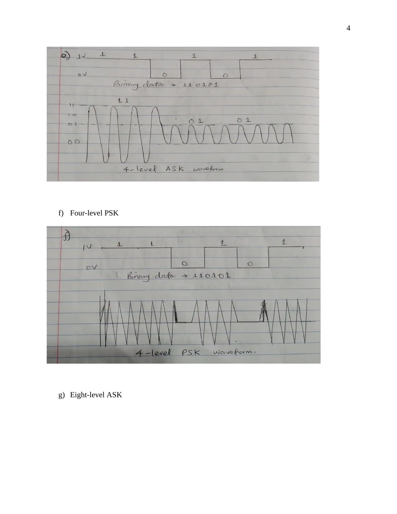
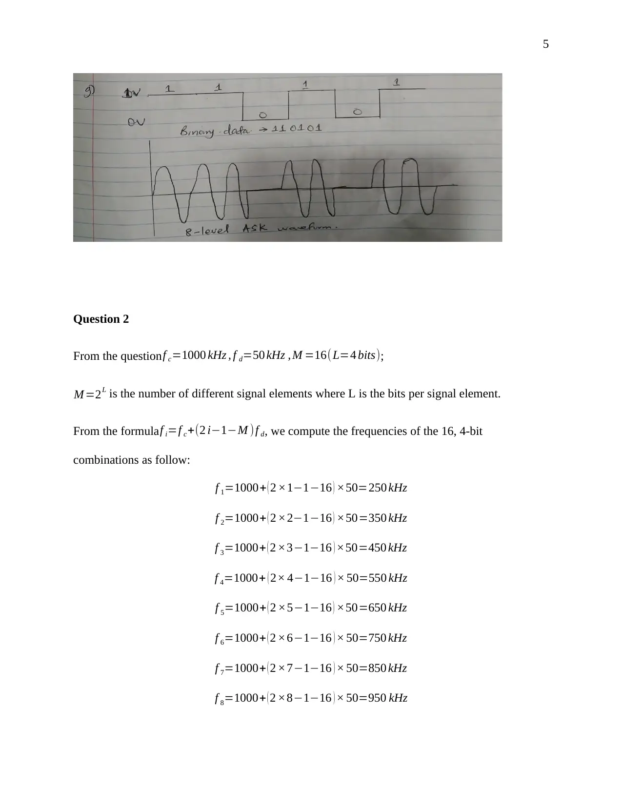
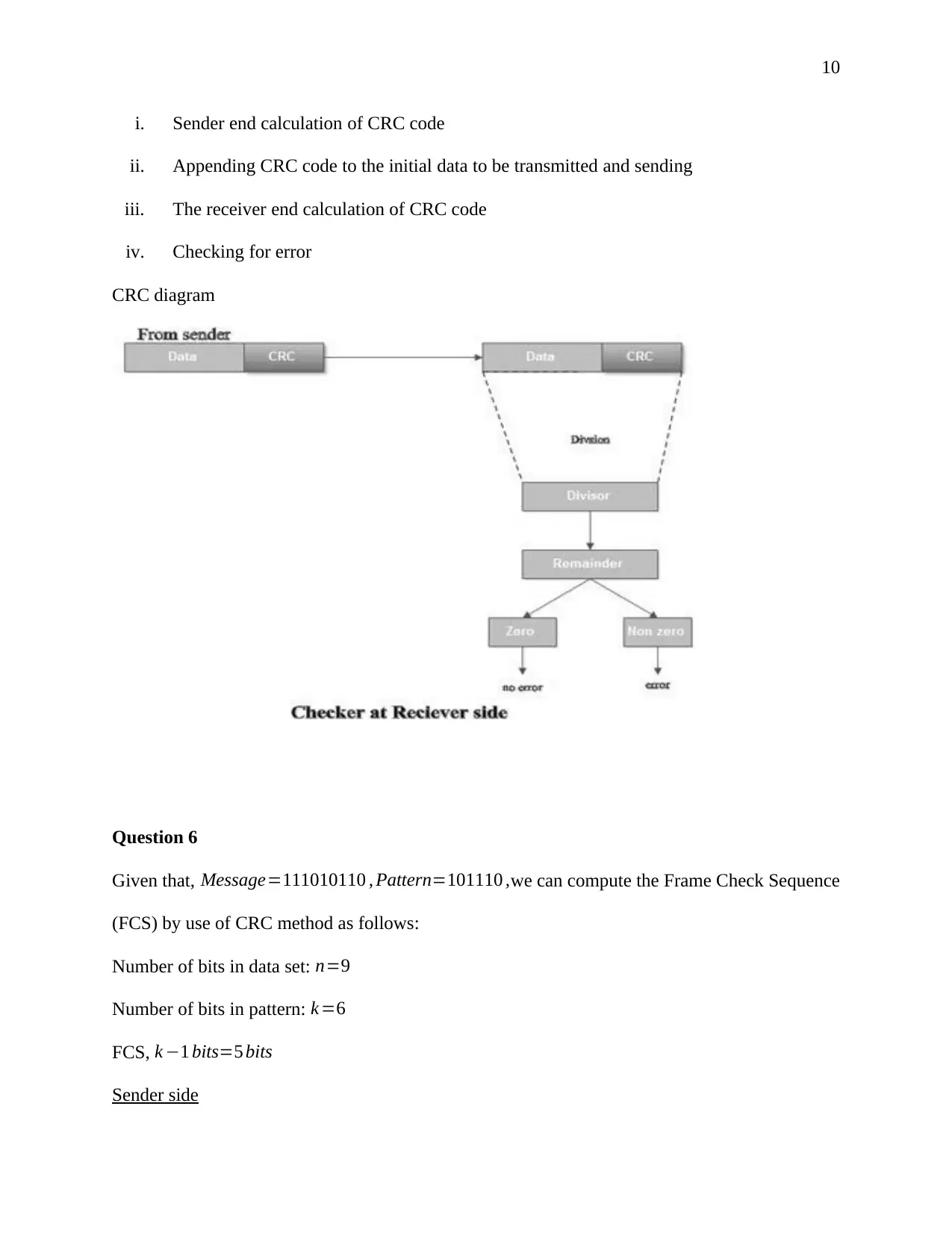
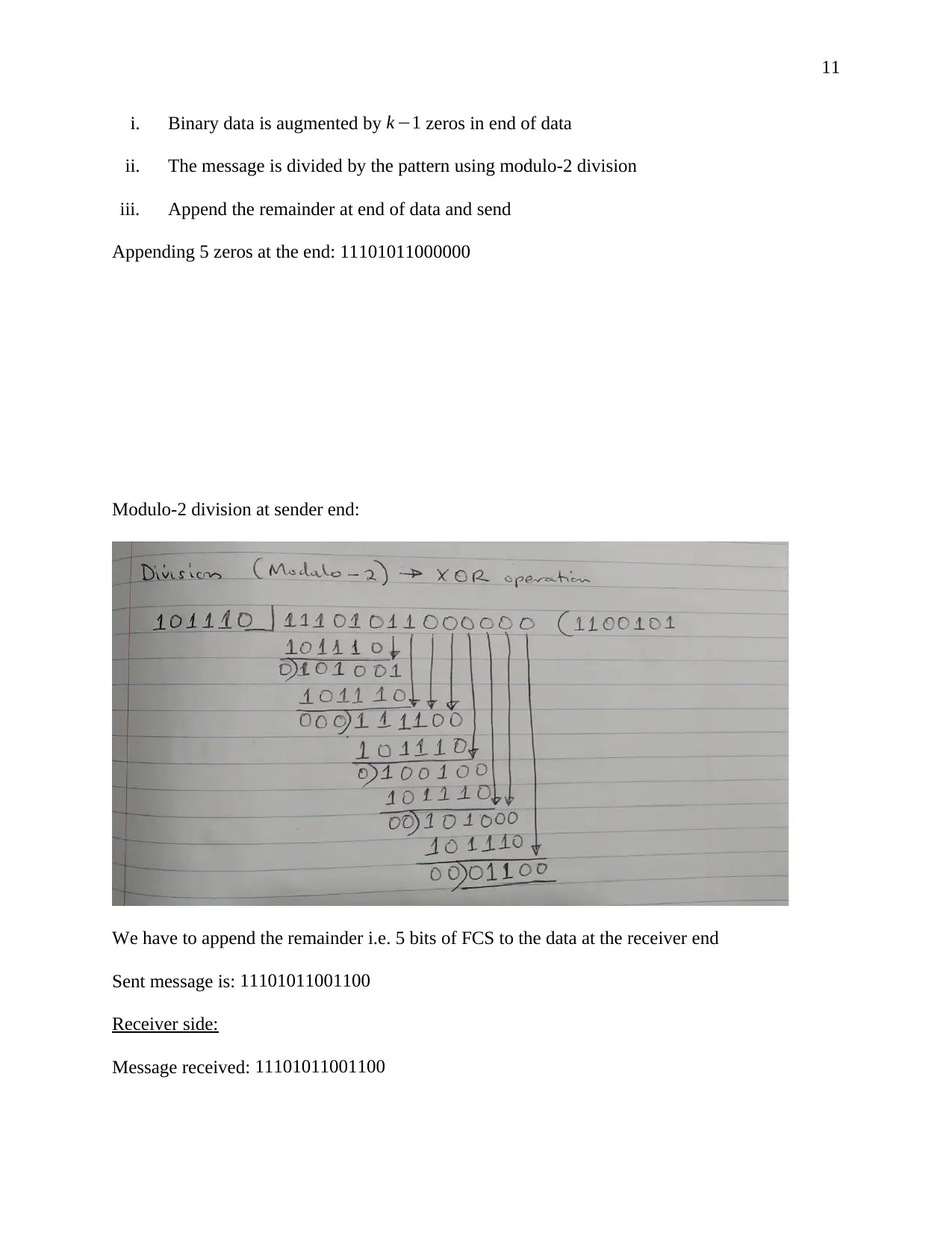
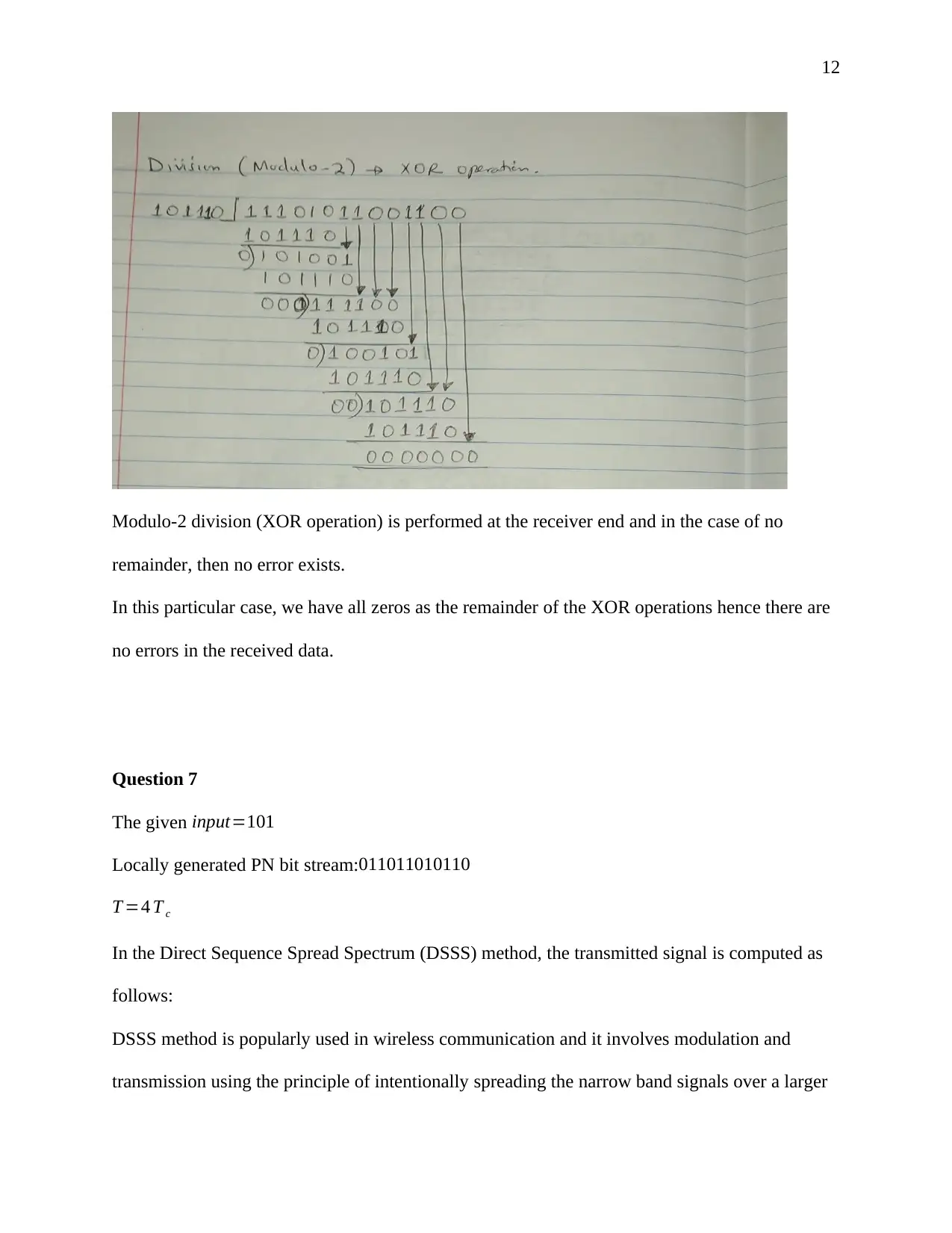
This document presents a comprehensive solution to a term paper assignment on wireless networks and communication. The assignment covers various topics, including the conversion of binary data to analog waveforms using different modulation techniques like ASK, FSK, PSK, and QAM. It includes calculations related to signal elements and frequencies. The solution also delves into Cyclic Redundancy Check (CRC) code generation and error detection, explaining the process with sender and receiver-end calculations and diagrams. Furthermore, the assignment addresses Direct Sequence Spread Spectrum (DSSS) and its application in wireless communication, including the use of XOR operations. Finally, the solution discusses the advantages of hexagonal cell structures in cellular networks, comparing them to square and circle-shaped cells in terms of coverage and performance. This assignment is designed to provide a complete understanding of key concepts in wireless communication and network design.
tabler-icon-diamond-filled.svg

Contribute Materials

Your contribution can guide someone’s learning journey. Share your documents today.
Document Page
1
Wireless Networks and Communication
Term Paper
Date
840 words
Student Name
Institution Name
tabler-icon-diamond-filled.svg

Secure Best Marks with AI Grader

Need help grading? Try our AI Grader for instant feedback on your assignments.
Document Page
2
Question 1
Conversion of the binary data 110101 to analog waveforms using:
a) Two-level ASK
b) Two-level FSK
c) Two-level PSK
Document Page
3
d) Differential PSK
e) Four-level ASK
Document Page
4
f) Four-level PSK
g) Eight-level ASK
tabler-icon-diamond-filled.svg

Secure Best Marks with AI Grader

Need help grading? Try our AI Grader for instant feedback on your assignments.
Document Page
5
Question 2
From the questionf c=1000 kHz , f d=50 kHz , M =16( L=4 bits);
M =2L is the number of different signal elements where L is the bits per signal element.
From the formulaf i=f c+(2 i1M )f d, we compute the frequencies of the 16, 4-bit
combinations as follow:
f 1=1000+ ( 2 ×1116 ) ×50=250 kHz
f 2=1000+ ( 2 ×2116 ) ×50=350 kHz
f 3=1000+ ( 2 ×3116 ) ×50=450 kHz
f 4=1000+ ( 2× 4116 ) × 50=550 kHz
f 5=1000+ ( 2 ×5116 ) ×50=650 kHz
f 6=1000+ ( 2 ×6116 ) × 50=750 kHz
f 7=1000+ ( 2 ×7116 ) × 50=850 kHz
f 8=1000+ ( 2 ×8116 ) × 50=950 kHz
Document Page
6
f 9=1000+ ( 2 ×9116 ) × 50=1050 kHz
f 10=1000+ ( 2 ×10116 ) ×50=1150 kHz
f 11=1000+ ( 2× 11116 ) × 50=1250 kHz
f 12=1000+ ( 2× 12116 ) × 50=1350 kHz
f 13=1000+ ( 2× 13116 ) ×50=1450 kHz
f 14=1000+ ( 2 ×14116 ) × 50=1550 kHz
f 15=1000+ ( 2× 15116 ) ×50=1650 kHz
f 16=1000+ ( 2 ×16116 ) ×50=1750 kHz
Question 3
Document Page
7
Question 4
For a 16-QAM modulation, symbol ¿ log2 16=4 bits
Here, the 16-QAM Constellation Diagram is constructed using 4-Amplitude Shift Keying (ASK)
signals. In the 4-level ASK signals, there 4 different amplitudes and phase levels.
Assume amplitude levels of (3 ,1 ,1 , 3) and 4 variables abcd.
cd 00 01 11 10
ab
00 0 1 3 2
tabler-icon-diamond-filled.svg

Paraphrase This Document

Need a fresh take? Get an instant paraphrase of this document with our AI Paraphraser
Document Page
8
01 4 5 7 6
11 12 13 15 14
10 8 9 11 10
Taking 00 3
01 1
11 +1
10 +3
With the phase levels of (45° , 135° , 225 ° , 315 °)
Input symbols to
16-QAM
modulator
Representation
of binary
Output of 16-QAM
(ab + jcd)
0 0000 3 j 3
1 0001 3 j 1
2 0010 3+ j 3
3 0011 3+ j1
4 0100 1 j3
5 0101 1 j 1
6 0110 1 j3
7 0111 1+ j 1
8 1000 3 j 3
9 1001 3 j 1
Document Page
9
10 1010 3+ j3
11 1011 3+ j1
12 1100 1 j3
13 1101 1 j1
14 1110 1+ j 3
15 1111 1+ j 1
Question 5
In the generation of the CRC code, the generator polynomial say G(x) must be agreed upon by
the sender and the receiver beforehand. Bit strings representation comes in terms of polynomials
with the coefficients as 0’s and 1’s.
CRC uses modulo-2 division i.e. the XOR operation.
The process of error detection in a CRC involves the following steps:
Document Page
10
i. Sender end calculation of CRC code
ii. Appending CRC code to the initial data to be transmitted and sending
iii. The receiver end calculation of CRC code
iv. Checking for error
CRC diagram
Question 6
Given that, Message=111010110 , Pattern=101110 ,we can compute the Frame Check Sequence
(FCS) by use of CRC method as follows:
Number of bits in data set: n=9
Number of bits in pattern: k =6
FCS, k 1 bits=5 bits
Sender side
tabler-icon-diamond-filled.svg

Secure Best Marks with AI Grader

Need help grading? Try our AI Grader for instant feedback on your assignments.
Document Page
11
i. Binary data is augmented by k 1 zeros in end of data
ii. The message is divided by the pattern using modulo-2 division
iii. Append the remainder at end of data and send
Appending 5 zeros at the end: 11101011000000
Modulo-2 division at sender end:
We have to append the remainder i.e. 5 bits of FCS to the data at the receiver end
Sent message is: 11101011001100
Receiver side:
Message received: 11101011001100
Document Page
12
Modulo-2 division (XOR operation) is performed at the receiver end and in the case of no
remainder, then no error exists.
In this particular case, we have all zeros as the remainder of the XOR operations hence there are
no errors in the received data.
Question 7
The given input=101
Locally generated PN bit stream: 011011010110
T =4 T c
In the Direct Sequence Spread Spectrum (DSSS) method, the transmitted signal is computed as
follows:
DSSS method is popularly used in wireless communication and it involves modulation and
transmission using the principle of intentionally spreading the narrow band signals over a larger
Document Page
13
BW (bandwidth). Encoding is done to the input bit stream with a PN bit stream (a bit stream of
larger BW). The XOR gate operation is used to combine the two bit streams as shown in the
table below.
Table 7.1: XOR logic
X Y Z=XY
0 0 0
0 1 1
1 0 1
1 1 0
From the above given information, each bit in the input stream is spread over the 4- PN stream
bits
Transmitted Signal=Input PN
XOR operation:
The transmitted signal is100 011101 101 as shown above.
Question 8
With hexagonal shaped cells, the whole area is covered without overlaps as opposed to the circle
and square-shaped cells that must overlap partially to avoid having gaps between them. As a
consequence, the square and circle shaped cells when arranged, do not cover the entire network
111 000111 111 Input stream
011 011 010110 PN stream
100 011101 101 Transmitted signal
tabler-icon-diamond-filled.svg

Paraphrase This Document

Need a fresh take? Get an instant paraphrase of this document with our AI Paraphraser
Document Page
14
coverage area thus leaving blackspot areas where no signals can reach. The arrangement of
hexagonal cells, however, is done such that there are no blackspots existing between the cells.
Generally, the shape and arrangement of the cells affect cellular network performance to a great
extent. The square and circle shaped cells are more vulnerable to path loss attenuation and RF
signal attenuation as a consequence of co-channel interference. The hexagonal shaped cells are,
therefore, more convenient and flexible than their counterparts and are often employed in,
design, analysis, planning and implementation of cellular networks.
The hexagonal architecture is also more appropriate for simulations and cellular network
planning and design due to the accuracy it offers. The in-radius and circumradius approximations
have greater similarities to the hexagonal architecture than to the square shaped cells.
chevron_up_icon
1 out of 14
circle_padding
hide_on_mobile
zoom_out_icon
logo.png

Your All-in-One AI-Powered Toolkit for Academic Success.

Available 24*7 on WhatsApp / Email

[object Object]