Training Manual for New Treatment Plant Operators: MIWR Plant Report
VerifiedAdded on 2022/10/04
|13
|4556
|28
Report
AI Summary
This document serves as a comprehensive training manual for new operators at the Magnetic Island Water Recycling (MIWR) plant, focusing on advanced water and wastewater engineering principles. It begins with an introduction to the plant's membrane bioreactor (MBR) system, designed for removing phosphorus, nitrogen, and solids from wastewater through primary, secondary, and tertiary treatment stages. The manual details the treatment process, including screening, grit removal, balance tank operation, and the three stages of secondary treatment (anaerobic, aerobic, and anoxic tanks), followed by membrane filtration and disinfection. The document includes a process flow diagram, and a table outlining common effluent quality scenarios, their causes, and recommended actions. The report also analyzes the plant's performance, calculating key parameters such as Hydraulic Retention Time (HRT), Sludge Age, BOD load, and F/M ratio, and Mixed Liquor Volatile Suspended Solids (MLVSS). The provided data from the certificate of analysis assists in understanding the plant's efficiency and operational requirements.
Advanced Water & Wastewater Engineering
Author
Department, University
Address
Training Manual for New Treatment Plant Operators
INTRODUCTION
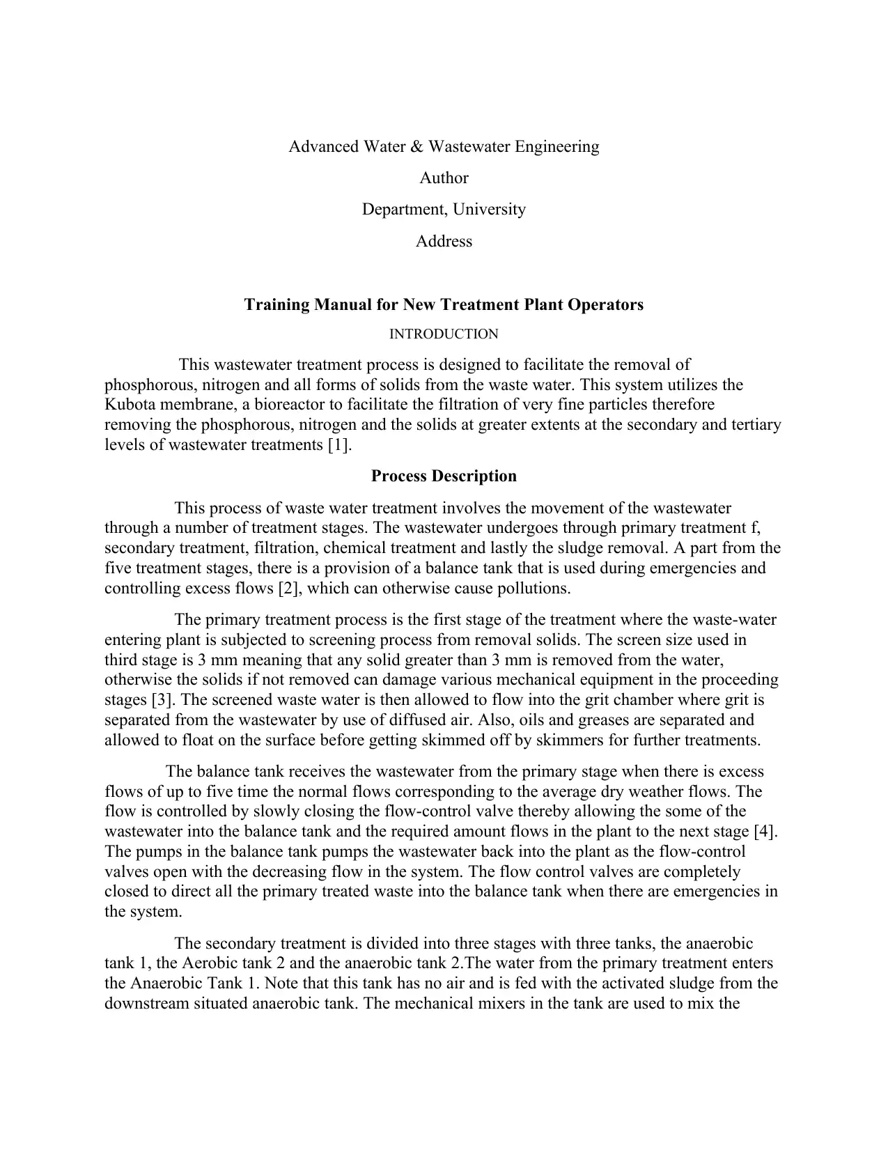
This wastewater treatment process is designed to facilitate the removal of
phosphorous, nitrogen and all forms of solids from the waste water. This system utilizes the
Kubota membrane, a bioreactor to facilitate the filtration of very fine particles therefore
removing the phosphorous, nitrogen and the solids at greater extents at the secondary and tertiary
levels of wastewater treatments [1].
Process Description
This process of waste water treatment involves the movement of the wastewater
through a number of treatment stages. The wastewater undergoes through primary treatment f,
secondary treatment, filtration, chemical treatment and lastly the sludge removal. A part from the
five treatment stages, there is a provision of a balance tank that is used during emergencies and
controlling excess flows [2], which can otherwise cause pollutions.
The primary treatment process is the first stage of the treatment where the waste-water
entering plant is subjected to screening process from removal solids. The screen size used in
third stage is 3 mm meaning that any solid greater than 3 mm is removed from the water,
otherwise the solids if not removed can damage various mechanical equipment in the proceeding
stages [3]. The screened waste water is then allowed to flow into the grit chamber where grit is
separated from the wastewater by use of diffused air. Also, oils and greases are separated and
allowed to float on the surface before getting skimmed off by skimmers for further treatments.
The balance tank receives the wastewater from the primary stage when there is excess
flows of up to five time the normal flows corresponding to the average dry weather flows. The
flow is controlled by slowly closing the flow-control valve thereby allowing the some of the
wastewater into the balance tank and the required amount flows in the plant to the next stage [4].
The pumps in the balance tank pumps the wastewater back into the plant as the flow-control
valves open with the decreasing flow in the system. The flow control valves are completely
closed to direct all the primary treated waste into the balance tank when there are emergencies in
the system.
The secondary treatment is divided into three stages with three tanks, the anaerobic
tank 1, the Aerobic tank 2 and the anaerobic tank 2.The water from the primary treatment enters
the Anaerobic Tank 1. Note that this tank has no air and is fed with the activated sludge from the
downstream situated anaerobic tank. The mechanical mixers in the tank are used to mix the
Author
Department, University
Address
Training Manual for New Treatment Plant Operators
INTRODUCTION
This wastewater treatment process is designed to facilitate the removal of
phosphorous, nitrogen and all forms of solids from the waste water. This system utilizes the
Kubota membrane, a bioreactor to facilitate the filtration of very fine particles therefore
removing the phosphorous, nitrogen and the solids at greater extents at the secondary and tertiary
levels of wastewater treatments [1].
Process Description
This process of waste water treatment involves the movement of the wastewater
through a number of treatment stages. The wastewater undergoes through primary treatment f,
secondary treatment, filtration, chemical treatment and lastly the sludge removal. A part from the
five treatment stages, there is a provision of a balance tank that is used during emergencies and
controlling excess flows [2], which can otherwise cause pollutions.
The primary treatment process is the first stage of the treatment where the waste-water
entering plant is subjected to screening process from removal solids. The screen size used in
third stage is 3 mm meaning that any solid greater than 3 mm is removed from the water,
otherwise the solids if not removed can damage various mechanical equipment in the proceeding
stages [3]. The screened waste water is then allowed to flow into the grit chamber where grit is
separated from the wastewater by use of diffused air. Also, oils and greases are separated and
allowed to float on the surface before getting skimmed off by skimmers for further treatments.
The balance tank receives the wastewater from the primary stage when there is excess
flows of up to five time the normal flows corresponding to the average dry weather flows. The
flow is controlled by slowly closing the flow-control valve thereby allowing the some of the
wastewater into the balance tank and the required amount flows in the plant to the next stage [4].
The pumps in the balance tank pumps the wastewater back into the plant as the flow-control
valves open with the decreasing flow in the system. The flow control valves are completely
closed to direct all the primary treated waste into the balance tank when there are emergencies in
the system.
The secondary treatment is divided into three stages with three tanks, the anaerobic
tank 1, the Aerobic tank 2 and the anaerobic tank 2.The water from the primary treatment enters
the Anaerobic Tank 1. Note that this tank has no air and is fed with the activated sludge from the
downstream situated anaerobic tank. The mechanical mixers in the tank are used to mix the
Paraphrase This Document
Need a fresh take? Get an instant paraphrase of this document with our AI Paraphraser
wastewater continuously in the tank leading to the breakdown of nitrates when oxygen is utilized
in the production of Autotrophic bacteria thus reducing the level of nutrients in the waste water.
The sludge from Tank 1 is allowed to flow into the Aerobic Tank 2 and supplied
with dissolved oxygen through the computer controlled variable frequency drive blowers. The
reactions by the heterotrophic bacteria take place in this tank to remove other compounds like
phosphorous and ammonia from the wastewater [5]. Aluminium sulphate is also introduced in
this tank to remove any excess phosphorous [6] and acoustic dosing done to increase the low pH
[7] of the wastewater. Micro-organisms such as the protozoa are also introduced into the tank to
consume the bacteria this leaving a relatively cleaner wastewater. From the aerobic tank 2, the
sludge is directed into the anoxic tank 2 where the nitrate and nitrogen levels in the wastewater
are considerably reduced. The denitrification process is achieved through the autotrophic bacteria
in the tank where the nitrate is reduced to nitrogen by the bacteria.
The last process in the wastewater treatment is the filtration of the sludge through the
submerged membrane filtration. The sludge is retained in the filtration system for about 30 days
allowing for advanced filtration with the small membrane size of about 0.1 microns [8].Also,
there is formation of the bio-flora in the membrane with the longer stay of the sludge, permitting
of a more fine filtrations of the sludge. The membrane has a considerably high area to adequately
handle high sludge volumes. The effluent is then treated with chlorine for disinfection and
directed to storage tanks for other uses like irrigation. The wet sludge is dried in the beds to
obtain the sludge cakes before disposal in to the landfills.
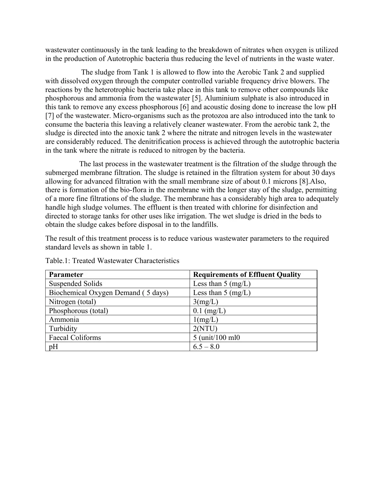
The result of this treatment process is to reduce various wastewater parameters to the required
standard levels as shown in table 1.
Table.1: Treated Wastewater Characteristics
Parameter Requirements of Effluent Quality
Suspended Solids Less than 5 (mg/L)
Biochemical Oxygen Demand ( 5 days) Less than 5 (mg/L)
Nitrogen (total) 3(mg/L)
Phosphorous (total) 0.1 (mg/L)
Ammonia 1(mg/L)
Turbidity 2(NTU)
Faecal Coliforms 5 (unit/100 ml0
pH 6.5 – 8.0
in the production of Autotrophic bacteria thus reducing the level of nutrients in the waste water.
The sludge from Tank 1 is allowed to flow into the Aerobic Tank 2 and supplied
with dissolved oxygen through the computer controlled variable frequency drive blowers. The
reactions by the heterotrophic bacteria take place in this tank to remove other compounds like
phosphorous and ammonia from the wastewater [5]. Aluminium sulphate is also introduced in
this tank to remove any excess phosphorous [6] and acoustic dosing done to increase the low pH
[7] of the wastewater. Micro-organisms such as the protozoa are also introduced into the tank to
consume the bacteria this leaving a relatively cleaner wastewater. From the aerobic tank 2, the
sludge is directed into the anoxic tank 2 where the nitrate and nitrogen levels in the wastewater
are considerably reduced. The denitrification process is achieved through the autotrophic bacteria
in the tank where the nitrate is reduced to nitrogen by the bacteria.
The last process in the wastewater treatment is the filtration of the sludge through the
submerged membrane filtration. The sludge is retained in the filtration system for about 30 days
allowing for advanced filtration with the small membrane size of about 0.1 microns [8].Also,
there is formation of the bio-flora in the membrane with the longer stay of the sludge, permitting
of a more fine filtrations of the sludge. The membrane has a considerably high area to adequately
handle high sludge volumes. The effluent is then treated with chlorine for disinfection and
directed to storage tanks for other uses like irrigation. The wet sludge is dried in the beds to
obtain the sludge cakes before disposal in to the landfills.
The result of this treatment process is to reduce various wastewater parameters to the required
standard levels as shown in table 1.
Table.1: Treated Wastewater Characteristics
Parameter Requirements of Effluent Quality
Suspended Solids Less than 5 (mg/L)
Biochemical Oxygen Demand ( 5 days) Less than 5 (mg/L)
Nitrogen (total) 3(mg/L)
Phosphorous (total) 0.1 (mg/L)
Ammonia 1(mg/L)
Turbidity 2(NTU)
Faecal Coliforms 5 (unit/100 ml0
pH 6.5 – 8.0
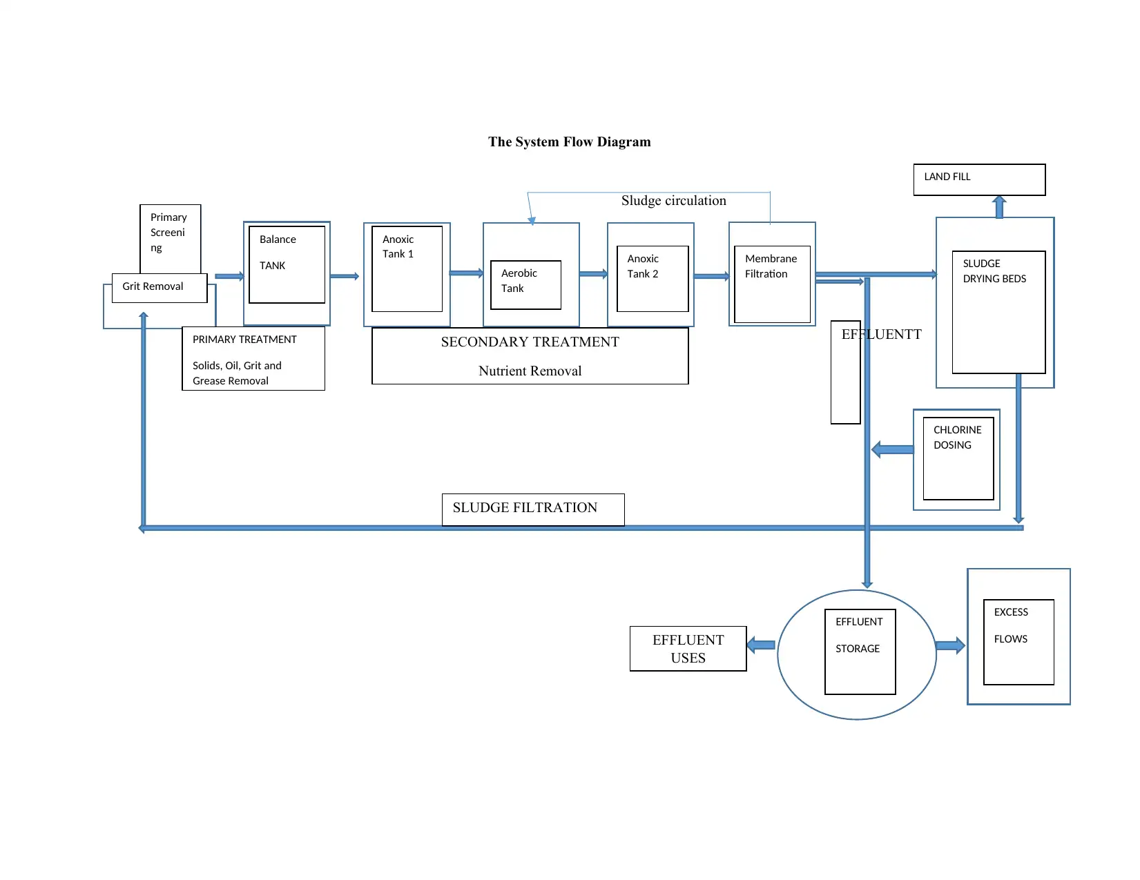
The System Flow Diagram
Sludge circulation
Primary
Screeni
ng Balance
TANK
Anoxic
Tank 1
Aerobic
Tank
Anoxic
Tank 2
Membrane
Filtration SLUDGE
DRYING BEDS
EXCESS
FLOWS
EFFLUENT
STORAGE
CHLORINE
DOSING
LAND FILL
Grit Removal
PRIMARY TREATMENT
Solids, Oil, Grit and
Grease Removal
SECONDARY TREATMENT
Nutrient Removal
EFFLUENTT
T
SLUDGE FILTRATION
EFFLUENT
USES
⊘ This is a preview!⊘
Do you want full access?
Subscribe today to unlock all pages.
Trusted by 1+ million students worldwide
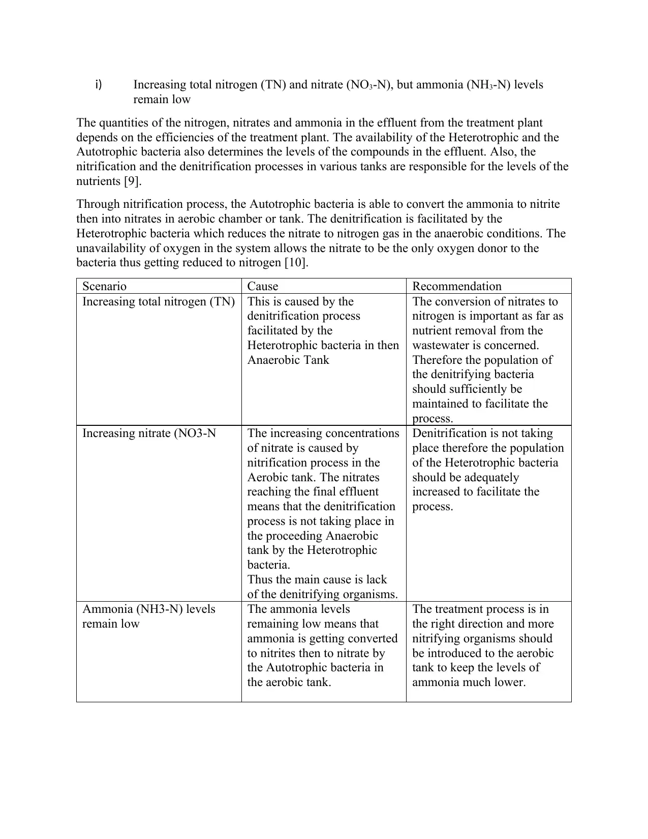
i) Increasing total nitrogen (TN) and nitrate (NO3-N), but ammonia (NH3-N) levels
remain low
The quantities of the nitrogen, nitrates and ammonia in the effluent from the treatment plant
depends on the efficiencies of the treatment plant. The availability of the Heterotrophic and the
Autotrophic bacteria also determines the levels of the compounds in the effluent. Also, the
nitrification and the denitrification processes in various tanks are responsible for the levels of the
nutrients [9].
Through nitrification process, the Autotrophic bacteria is able to convert the ammonia to nitrite
then into nitrates in aerobic chamber or tank. The denitrification is facilitated by the
Heterotrophic bacteria which reduces the nitrate to nitrogen gas in the anaerobic conditions. The
unavailability of oxygen in the system allows the nitrate to be the only oxygen donor to the
bacteria thus getting reduced to nitrogen [10].
Scenario Cause Recommendation
Increasing total nitrogen (TN) This is caused by the
denitrification process
facilitated by the
Heterotrophic bacteria in then
Anaerobic Tank
The conversion of nitrates to
nitrogen is important as far as
nutrient removal from the
wastewater is concerned.
Therefore the population of
the denitrifying bacteria
should sufficiently be
maintained to facilitate the
process.
Increasing nitrate (NO3-N The increasing concentrations
of nitrate is caused by
nitrification process in the
Aerobic tank. The nitrates
reaching the final effluent
means that the denitrification
process is not taking place in
the proceeding Anaerobic
tank by the Heterotrophic
bacteria.
Thus the main cause is lack
of the denitrifying organisms.
Denitrification is not taking
place therefore the population
of the Heterotrophic bacteria
should be adequately
increased to facilitate the
process.
Ammonia (NH3-N) levels
remain low
The ammonia levels
remaining low means that
ammonia is getting converted
to nitrites then to nitrate by
the Autotrophic bacteria in
the aerobic tank.
The treatment process is in
the right direction and more
nitrifying organisms should
be introduced to the aerobic
tank to keep the levels of
ammonia much lower.
remain low
The quantities of the nitrogen, nitrates and ammonia in the effluent from the treatment plant
depends on the efficiencies of the treatment plant. The availability of the Heterotrophic and the
Autotrophic bacteria also determines the levels of the compounds in the effluent. Also, the
nitrification and the denitrification processes in various tanks are responsible for the levels of the
nutrients [9].
Through nitrification process, the Autotrophic bacteria is able to convert the ammonia to nitrite
then into nitrates in aerobic chamber or tank. The denitrification is facilitated by the
Heterotrophic bacteria which reduces the nitrate to nitrogen gas in the anaerobic conditions. The
unavailability of oxygen in the system allows the nitrate to be the only oxygen donor to the
bacteria thus getting reduced to nitrogen [10].
Scenario Cause Recommendation
Increasing total nitrogen (TN) This is caused by the
denitrification process
facilitated by the
Heterotrophic bacteria in then
Anaerobic Tank
The conversion of nitrates to
nitrogen is important as far as
nutrient removal from the
wastewater is concerned.
Therefore the population of
the denitrifying bacteria
should sufficiently be
maintained to facilitate the
process.
Increasing nitrate (NO3-N The increasing concentrations
of nitrate is caused by
nitrification process in the
Aerobic tank. The nitrates
reaching the final effluent
means that the denitrification
process is not taking place in
the proceeding Anaerobic
tank by the Heterotrophic
bacteria.
Thus the main cause is lack
of the denitrifying organisms.
Denitrification is not taking
place therefore the population
of the Heterotrophic bacteria
should be adequately
increased to facilitate the
process.
Ammonia (NH3-N) levels
remain low
The ammonia levels
remaining low means that
ammonia is getting converted
to nitrites then to nitrate by
the Autotrophic bacteria in
the aerobic tank.
The treatment process is in
the right direction and more
nitrifying organisms should
be introduced to the aerobic
tank to keep the levels of
ammonia much lower.
Paraphrase This Document
Need a fresh take? Get an instant paraphrase of this document with our AI Paraphraser
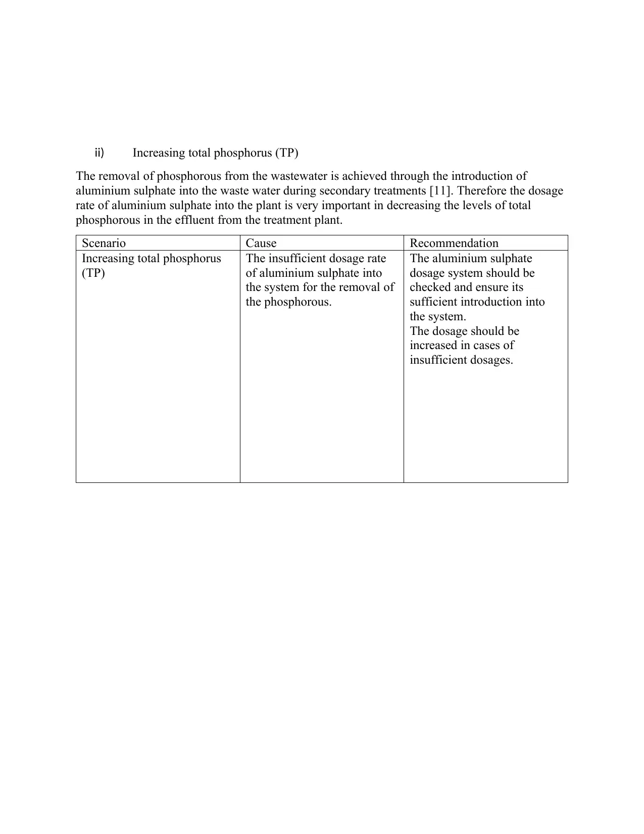
ii) Increasing total phosphorus (TP)
The removal of phosphorous from the wastewater is achieved through the introduction of
aluminium sulphate into the waste water during secondary treatments [11]. Therefore the dosage
rate of aluminium sulphate into the plant is very important in decreasing the levels of total
phosphorous in the effluent from the treatment plant.
Scenario Cause Recommendation
Increasing total phosphorus
(TP)
The insufficient dosage rate
of aluminium sulphate into
the system for the removal of
the phosphorous.
The aluminium sulphate
dosage system should be
checked and ensure its
sufficient introduction into
the system.
The dosage should be
increased in cases of
insufficient dosages.
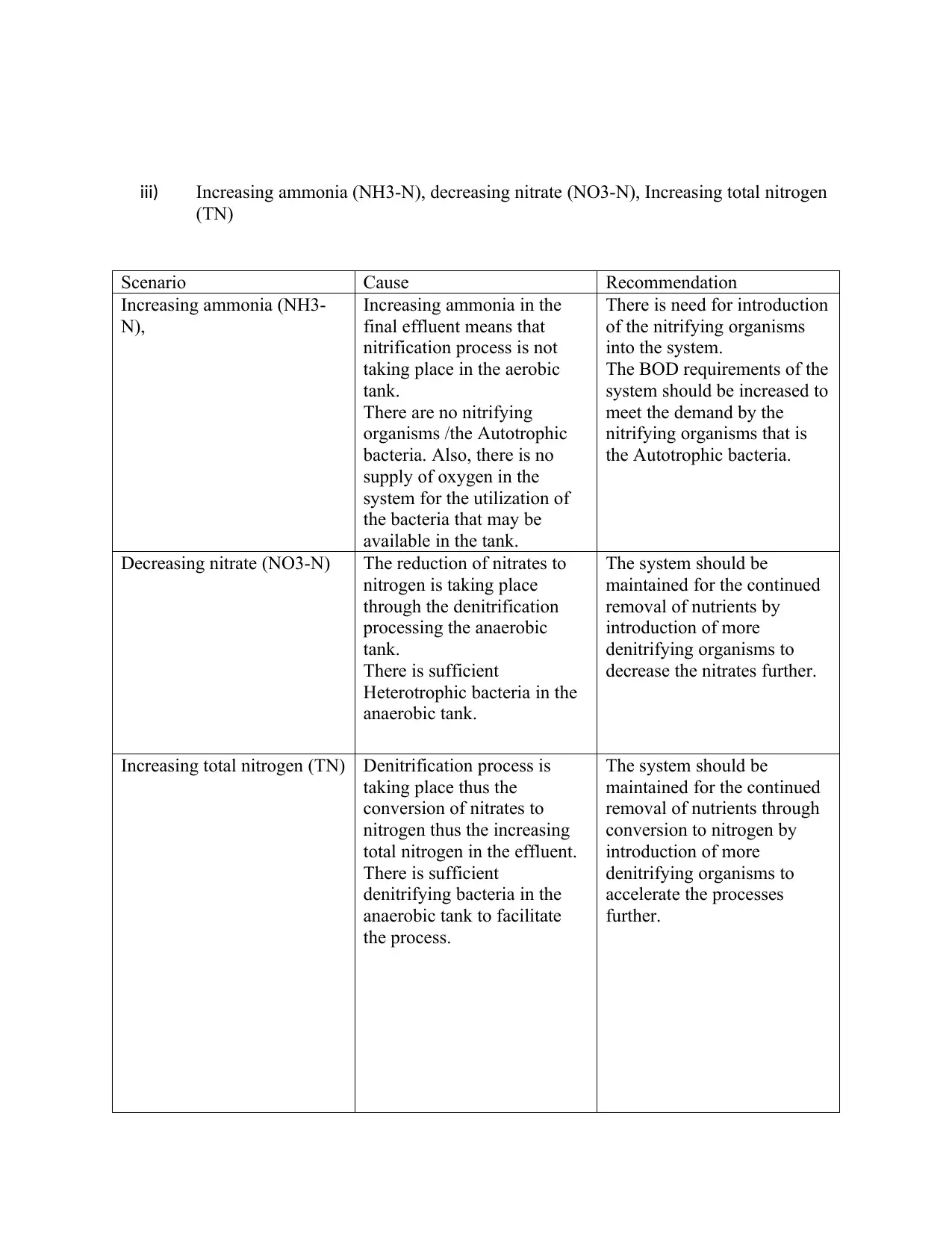
iii) Increasing ammonia (NH3-N), decreasing nitrate (NO3-N), Increasing total nitrogen
(TN)
Scenario Cause Recommendation
Increasing ammonia (NH3-
N),
Increasing ammonia in the
final effluent means that
nitrification process is not
taking place in the aerobic
tank.
There are no nitrifying
organisms /the Autotrophic
bacteria. Also, there is no
supply of oxygen in the
system for the utilization of
the bacteria that may be
available in the tank.
There is need for introduction
of the nitrifying organisms
into the system.
The BOD requirements of the
system should be increased to
meet the demand by the
nitrifying organisms that is
the Autotrophic bacteria.
Decreasing nitrate (NO3-N) The reduction of nitrates to
nitrogen is taking place
through the denitrification
processing the anaerobic
tank.
There is sufficient
Heterotrophic bacteria in the
anaerobic tank.
The system should be
maintained for the continued
removal of nutrients by
introduction of more
denitrifying organisms to
decrease the nitrates further.
Increasing total nitrogen (TN) Denitrification process is
taking place thus the
conversion of nitrates to
nitrogen thus the increasing
total nitrogen in the effluent.
There is sufficient
denitrifying bacteria in the
anaerobic tank to facilitate
the process.
The system should be
maintained for the continued
removal of nutrients through
conversion to nitrogen by
introduction of more
denitrifying organisms to
accelerate the processes
further.
⊘ This is a preview!⊘
Do you want full access?
Subscribe today to unlock all pages.
Trusted by 1+ million students worldwide
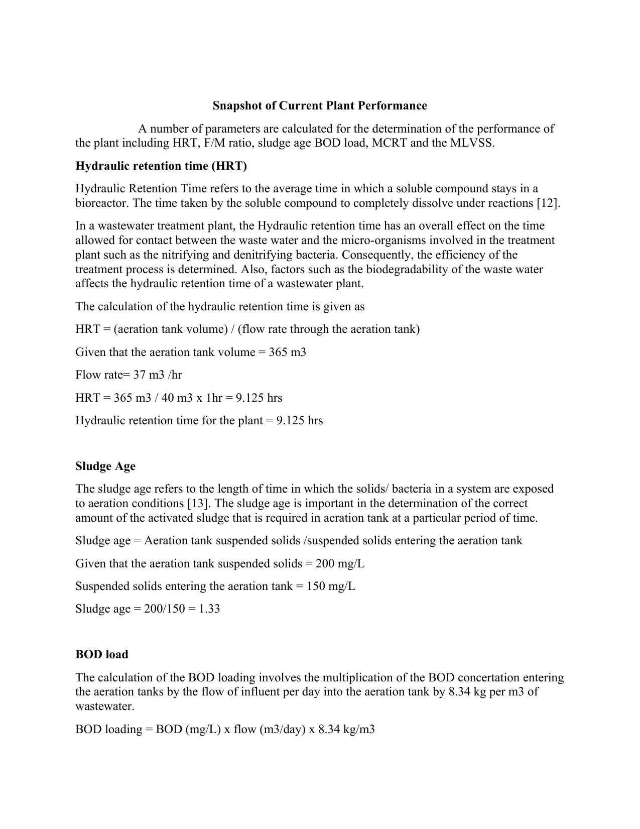
Snapshot of Current Plant Performance
A number of parameters are calculated for the determination of the performance of
the plant including HRT, F/M ratio, sludge age BOD load, MCRT and the MLVSS.
Hydraulic retention time (HRT)
Hydraulic Retention Time refers to the average time in which a soluble compound stays in a
bioreactor. The time taken by the soluble compound to completely dissolve under reactions [12].
In a wastewater treatment plant, the Hydraulic retention time has an overall effect on the time
allowed for contact between the waste water and the micro-organisms involved in the treatment
plant such as the nitrifying and denitrifying bacteria. Consequently, the efficiency of the
treatment process is determined. Also, factors such as the biodegradability of the waste water
affects the hydraulic retention time of a wastewater plant.
The calculation of the hydraulic retention time is given as
HRT = (aeration tank volume) / (flow rate through the aeration tank)
Given that the aeration tank volume = 365 m3
Flow rate= 37 m3 /hr
HRT = 365 m3 / 40 m3 x 1hr = 9.125 hrs
Hydraulic retention time for the plant = 9.125 hrs
Sludge Age
The sludge age refers to the length of time in which the solids/ bacteria in a system are exposed
to aeration conditions [13]. The sludge age is important in the determination of the correct
amount of the activated sludge that is required in aeration tank at a particular period of time.
Sludge age = Aeration tank suspended solids /suspended solids entering the aeration tank
Given that the aeration tank suspended solids = 200 mg/L
Suspended solids entering the aeration tank = 150 mg/L
Sludge age = 200/150 = 1.33
BOD load
The calculation of the BOD loading involves the multiplication of the BOD concertation entering
the aeration tanks by the flow of influent per day into the aeration tank by 8.34 kg per m3 of
wastewater.
BOD loading = BOD (mg/L) x flow (m3/day) x 8.34 kg/m3
Paraphrase This Document
Need a fresh take? Get an instant paraphrase of this document with our AI Paraphraser
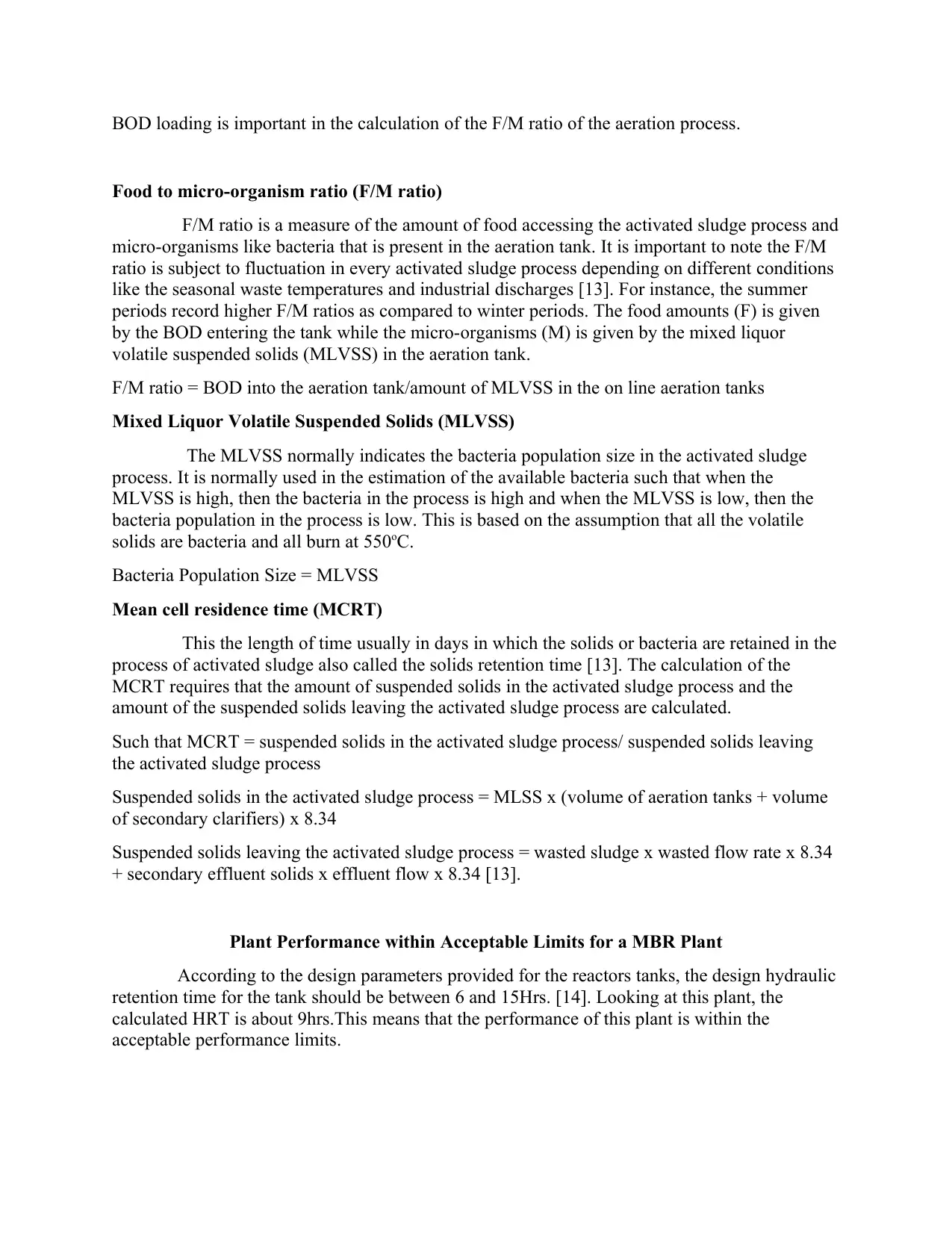
BOD loading is important in the calculation of the F/M ratio of the aeration process.
Food to micro-organism ratio (F/M ratio)
F/M ratio is a measure of the amount of food accessing the activated sludge process and
micro-organisms like bacteria that is present in the aeration tank. It is important to note the F/M
ratio is subject to fluctuation in every activated sludge process depending on different conditions
like the seasonal waste temperatures and industrial discharges [13]. For instance, the summer
periods record higher F/M ratios as compared to winter periods. The food amounts (F) is given
by the BOD entering the tank while the micro-organisms (M) is given by the mixed liquor
volatile suspended solids (MLVSS) in the aeration tank.
F/M ratio = BOD into the aeration tank/amount of MLVSS in the on line aeration tanks
Mixed Liquor Volatile Suspended Solids (MLVSS)
The MLVSS normally indicates the bacteria population size in the activated sludge
process. It is normally used in the estimation of the available bacteria such that when the
MLVSS is high, then the bacteria in the process is high and when the MLVSS is low, then the
bacteria population in the process is low. This is based on the assumption that all the volatile
solids are bacteria and all burn at 550oC.
Bacteria Population Size = MLVSS
Mean cell residence time (MCRT)
This the length of time usually in days in which the solids or bacteria are retained in the
process of activated sludge also called the solids retention time [13]. The calculation of the
MCRT requires that the amount of suspended solids in the activated sludge process and the
amount of the suspended solids leaving the activated sludge process are calculated.
Such that MCRT = suspended solids in the activated sludge process/ suspended solids leaving
the activated sludge process
Suspended solids in the activated sludge process = MLSS x (volume of aeration tanks + volume
of secondary clarifiers) x 8.34
Suspended solids leaving the activated sludge process = wasted sludge x wasted flow rate x 8.34
+ secondary effluent solids x effluent flow x 8.34 [13].
Plant Performance within Acceptable Limits for a MBR Plant
According to the design parameters provided for the reactors tanks, the design hydraulic
retention time for the tank should be between 6 and 15Hrs. [14]. Looking at this plant, the
calculated HRT is about 9hrs.This means that the performance of this plant is within the
acceptable performance limits.
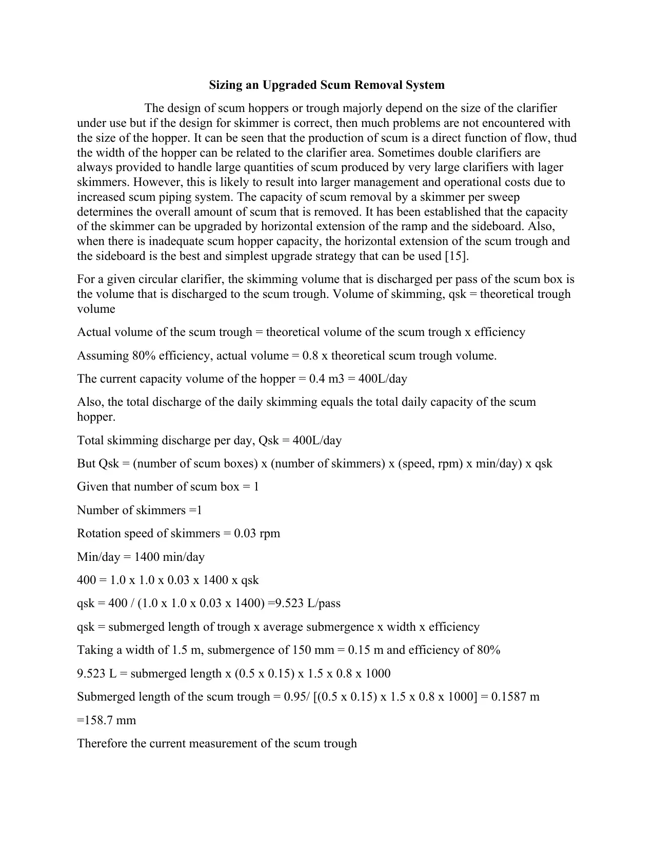
Sizing an Upgraded Scum Removal System
The design of scum hoppers or trough majorly depend on the size of the clarifier
under use but if the design for skimmer is correct, then much problems are not encountered with
the size of the hopper. It can be seen that the production of scum is a direct function of flow, thud
the width of the hopper can be related to the clarifier area. Sometimes double clarifiers are
always provided to handle large quantities of scum produced by very large clarifiers with lager
skimmers. However, this is likely to result into larger management and operational costs due to
increased scum piping system. The capacity of scum removal by a skimmer per sweep
determines the overall amount of scum that is removed. It has been established that the capacity
of the skimmer can be upgraded by horizontal extension of the ramp and the sideboard. Also,
when there is inadequate scum hopper capacity, the horizontal extension of the scum trough and
the sideboard is the best and simplest upgrade strategy that can be used [15].
For a given circular clarifier, the skimming volume that is discharged per pass of the scum box is
the volume that is discharged to the scum trough. Volume of skimming, qsk = theoretical trough
volume
Actual volume of the scum trough = theoretical volume of the scum trough x efficiency
Assuming 80% efficiency, actual volume = 0.8 x theoretical scum trough volume.
The current capacity volume of the hopper = 0.4 m3 = 400L/day
Also, the total discharge of the daily skimming equals the total daily capacity of the scum
hopper.
Total skimming discharge per day, Qsk = 400L/day
But Qsk = (number of scum boxes) x (number of skimmers) x (speed, rpm) x min/day) x qsk
Given that number of scum box = 1
Number of skimmers =1
Rotation speed of skimmers = 0.03 rpm
Min/day = 1400 min/day
400 = 1.0 x 1.0 x 0.03 x 1400 x qsk
qsk = 400 / (1.0 x 1.0 x 0.03 x 1400) =9.523 L/pass
qsk = submerged length of trough x average submergence x width x efficiency
Taking a width of 1.5 m, submergence of 150 mm = 0.15 m and efficiency of 80%
9.523 L = submerged length x (0.5 x 0.15) x 1.5 x 0.8 x 1000
Submerged length of the scum trough = 0.95/ [(0.5 x 0.15) x 1.5 x 0.8 x 1000] = 0.1587 m
=158.7 mm
Therefore the current measurement of the scum trough
⊘ This is a preview!⊘
Do you want full access?
Subscribe today to unlock all pages.
Trusted by 1+ million students worldwide
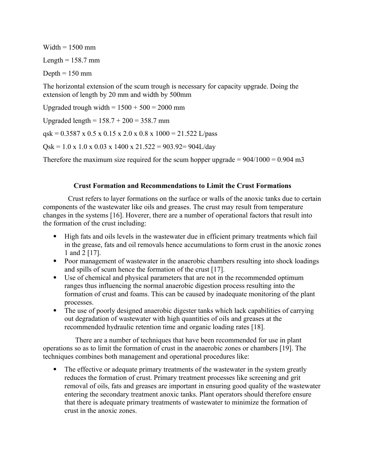
Width = 1500 mm
Length = 158.7 mm
Depth = 150 mm
The horizontal extension of the scum trough is necessary for capacity upgrade. Doing the
extension of length by 20 mm and width by 500mm
Upgraded trough width = 1500 + 500 = 2000 mm
Upgraded length = 158.7 + 200 = 358.7 mm
qsk = 0.3587 x 0.5 x 0.15 x 2.0 x 0.8 x 1000 = 21.522 L/pass
Qsk = 1.0 x 1.0 x 0.03 x 1400 x 21.522 = 903.92= 904L/day
Therefore the maximum size required for the scum hopper upgrade = 904/1000 = 0.904 m3
Crust Formation and Recommendations to Limit the Crust Formations
Crust refers to layer formations on the surface or walls of the anoxic tanks due to certain
components of the wastewater like oils and greases. The crust may result from temperature
changes in the systems [16]. Hoverer, there are a number of operational factors that result into
the formation of the crust including:
High fats and oils levels in the wastewater due in efficient primary treatments which fail
in the grease, fats and oil removals hence accumulations to form crust in the anoxic zones
1 and 2 [17].
Poor management of wastewater in the anaerobic chambers resulting into shock loadings
and spills of scum hence the formation of the crust [17].
Use of chemical and physical parameters that are not in the recommended optimum
ranges thus influencing the normal anaerobic digestion process resulting into the
formation of crust and foams. This can be caused by inadequate monitoring of the plant
processes.
The use of poorly designed anaerobic digester tanks which lack capabilities of carrying
out degradation of wastewater with high quantities of oils and greases at the
recommended hydraulic retention time and organic loading rates [18].
There are a number of techniques that have been recommended for use in plant
operations so as to limit the formation of crust in the anaerobic zones or chambers [19]. The
techniques combines both management and operational procedures like:
The effective or adequate primary treatments of the wastewater in the system greatly
reduces the formation of crust. Primary treatment processes like screening and grit
removal of oils, fats and greases are important in ensuring good quality of the wastewater
entering the secondary treatment anoxic tanks. Plant operators should therefore ensure
that there is adequate primary treatments of wastewater to minimize the formation of
crust in the anoxic zones.
Paraphrase This Document
Need a fresh take? Get an instant paraphrase of this document with our AI Paraphraser
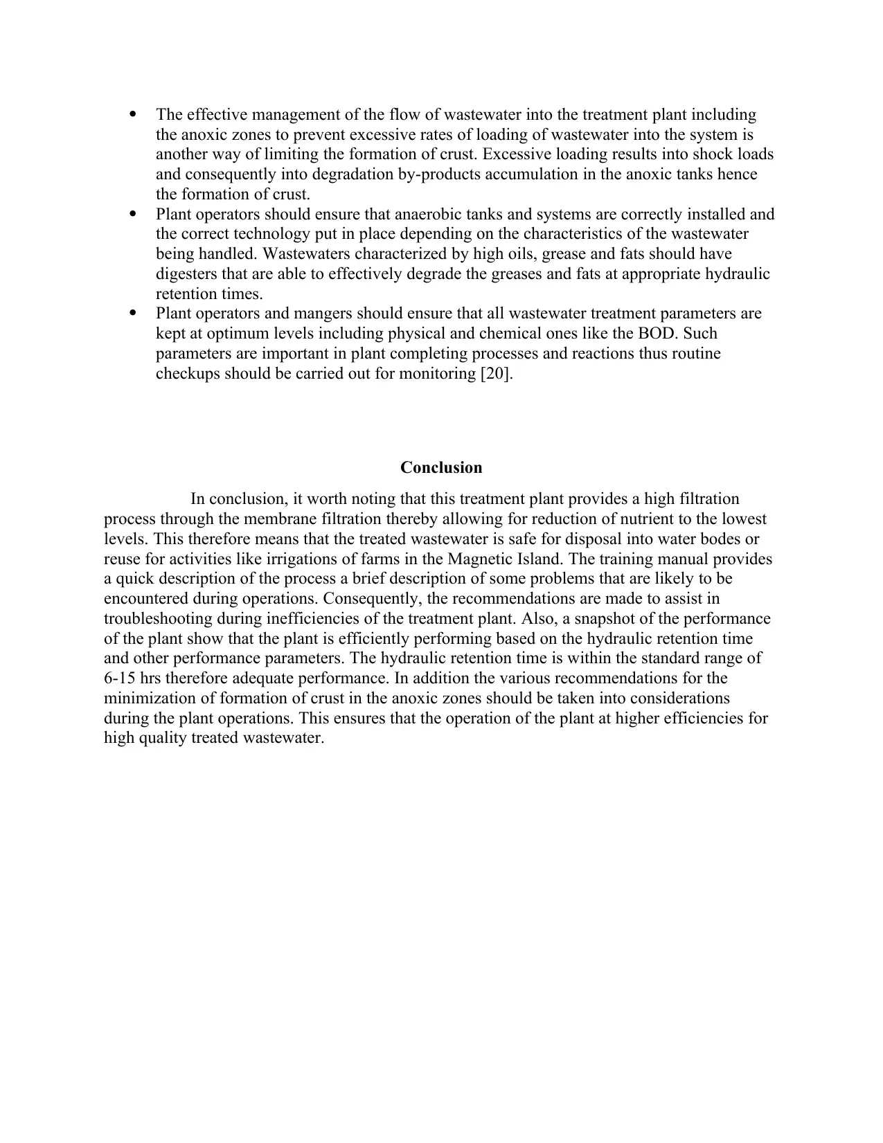
The effective management of the flow of wastewater into the treatment plant including
the anoxic zones to prevent excessive rates of loading of wastewater into the system is
another way of limiting the formation of crust. Excessive loading results into shock loads
and consequently into degradation by-products accumulation in the anoxic tanks hence
the formation of crust.
Plant operators should ensure that anaerobic tanks and systems are correctly installed and
the correct technology put in place depending on the characteristics of the wastewater
being handled. Wastewaters characterized by high oils, grease and fats should have
digesters that are able to effectively degrade the greases and fats at appropriate hydraulic
retention times.
Plant operators and mangers should ensure that all wastewater treatment parameters are
kept at optimum levels including physical and chemical ones like the BOD. Such
parameters are important in plant completing processes and reactions thus routine
checkups should be carried out for monitoring [20].
Conclusion
In conclusion, it worth noting that this treatment plant provides a high filtration
process through the membrane filtration thereby allowing for reduction of nutrient to the lowest
levels. This therefore means that the treated wastewater is safe for disposal into water bodes or
reuse for activities like irrigations of farms in the Magnetic Island. The training manual provides
a quick description of the process a brief description of some problems that are likely to be
encountered during operations. Consequently, the recommendations are made to assist in
troubleshooting during inefficiencies of the treatment plant. Also, a snapshot of the performance
of the plant show that the plant is efficiently performing based on the hydraulic retention time
and other performance parameters. The hydraulic retention time is within the standard range of
6-15 hrs therefore adequate performance. In addition the various recommendations for the
minimization of formation of crust in the anoxic zones should be taken into considerations
during the plant operations. This ensures that the operation of the plant at higher efficiencies for
high quality treated wastewater.
REFERENCES
[1] Iorhemen, Oliver Terna, Rania Ahmed Hamza, and Joo Hwa Tay. "Membrane bioreactor
(MBR) technology for wastewater treatment and reclamation: membrane fouling."
Membranes 6, no. 2 (2016): 33.
[2] Trifunović, Nemanja, Mohanad Abunada, Mukand Babel, and Maria Kennedy. "The role
of balancing tanks in optimal design of water distribution networks." Journal of
Water Supply: Research and Technology-Aqua 64, no. 5 (2015): 610-628.
[3] Quach-Cu, Jennipher, Bellanira Herrera-Lynch, Christine Marciniak, Scott Adams, April
Simmerman, and Ryan Reinke. "The effect of primary, secondary, and tertiary
wastewater treatment processes on antibiotic resistance gene (ARG) concentrations in
solid and dissolved wastewater fractions." Water 10, no. 1 (2018): 37.
[4] Chriscottrell. "Balance Tank Design for Deck-level Pools." PWTAG - The Pool Water
Treatment Advisory Group. Last modified May 22, 2019. Available:
https://www.pwtag.org/balance-tank-design-for-deck-level-pools-january-2016/.
[5] Yun, Yupan, Zifu Li, Yi-Hung Chen, Mayiani Saino, Shikun Cheng, and Lei Zheng.
"Elimination of nitrate in secondary effluent of wastewater treatment plants by Fe0
and Pd-Cu/diatomite." Journal of Water Reuse and Desalination 8, no. 1 (2018):
29-37.
[6] Gamage, Vidana, and Kumudu Chathurani Dharmasena. "Removal of Phosphorus from
Municipal Wastewater." PhD diss., Curtin University, 2016.
[7] Li, Na, Yi Hu, Yong-Ze Lu, Raymond J. Zeng, and Guo-Ping Sheng. "Multiple response
optimization of the coagulation process for upgrading the quality of effluent from
municipal wastewater treatment plant." Scientific reports 6 (2016): 26115.
[8] Cadore, Ígor Renz, Maurício Kipper da Silva, Liliane Damaris Pollo, and Isabel Cristina
Tessaro. "Wastewater treatment in a pilot-scale submerged membrane bioreactor: study
of hydrodynamics under constant operating pressure." Brazilian Journal of Chemical
Engineering 35, no. 1 (2018): 51-61.
[9] Gerardi, Michael H. Nitrification and denitrification in the activated sludge process. John
Wiley & Sons, 2003.
[10] Yu, Dongke. "Evaluation of effluent organic nitrogen and its impacts on receiving water
bodies." (2012).
[11] Ruzhitskaya, Olga, and Elena Gogina. "Methods for removing of phosphates from
wastewater." MATEC Web of Conferences. Vol. 106. EDP Sciences, 2017
[12] "HRT Hydraulic Retention Time (residence Time) Also τ (tau)." Water Treatment and
Purification - Lenntech. Accessed October 6, 2019.
https://www.lenntech.com/wwtp/hrt.htm.
[13] McCuen, Richard M. "Settleability problems and loss of solids in the Activated Sludge
Process." Journal of the American Water Resources Association 39, no. 1 (2003): 232.
⊘ This is a preview!⊘
Do you want full access?
Subscribe today to unlock all pages.
Trusted by 1+ million students worldwide
1 out of 13
Related Documents


Your All-in-One AI-Powered Toolkit for Academic Success.
+13062052269
info@desklib.com
Available 24*7 on WhatsApp / Email
![[object Object]](/_next/static/media/star-bottom.7253800d.svg)
Unlock your academic potential
Copyright © 2020–2026 A2Z Services. All Rights Reserved. Developed and managed by ZUCOL.