University of South Australia EEET 5102 Assignment 1 Solution
VerifiedAdded on 2022/10/02
|15
|2219
|29
Homework Assignment
AI Summary
This document presents a complete solution to a mobile communications assignment, addressing key concepts in cellular networks, propagation, and equalization techniques. The solution encompasses detailed calculations and derivations for various aspects of GSM systems, including cluster size, pathloss exponent, and antenna height requirements to meet specific signal-to-interference ratio (SIR) criteria. The assignment also delves into the analysis of multipath fading channels, including impulse response, detection rules, and error probability calculations for unequalized systems. Furthermore, the solution covers the design and implementation of a 3-tap zero-forcing equalizer and explores the impact of filtering on error probability, taking into account noise amplification. Finally, the assignment includes MATLAB code and simulations for bit error rate (BER) analysis, sectoring schemes to improve SIR, and sequence analysis for signal processing.

PART: (A)
1. What is the requirement on cluster size to support the GoS requirement?
Given Data:
Average call request rate = 3 calls/day
Average holding time = 15min
Gos = 2%
User density = 200 users
Traffic intensity per user = 3 × 15 = 45 Erlangs
Number of channels or cluster size = (200 × 45) ×2% = 180 channels`
2. What is the requirement on pathloss exponent to satisfy the SIR requirement?
Given:
S/I = 12Db;
N= 180 channels
Frequency reuse factor = 1/N
Frequency reuse factor = 1/180 = 0.0055
Frequency reuse factor = (N + S/I)1/ γ
Where,
γ = pathloss exponent
0.0055 = (180 + 120) 1/γ
γ = -1.0104
3. What is the minimum base station antenna height to satisfy the SIR requirement?
Given Data:
Fc = 1800MHz,
C= 3× 10⁸ m/sec
λ = c /f = 3× 10⁸ / 1800 × 103 =166.67 Hz.
Height of antenna = 0.25× λ = 0.25× 166.67 = 41.67 m.
4. Compute the worst case SIR experience.
Given:
R= 2 km
H= 6400km= Height of earth
D=√ 2hR
D = √ 2× 2× 6.4 ×106 = 5059.64
Suppose, n=4;
Paraphrase This Document
Need a fresh take? Get an instant paraphrase of this document with our AI Paraphraser

The worst case can be determined in SIR:
SIR = R−4
2 ( D−R )−4 + 2 ( D+ R )−4 +2 ( D )−4
SIR = 2−4
2 ( 5059.64−2 )−4 +2 (5059.64 +2 )−4 + 2 ( 5059.64 )−4
SIR = 7.0285
5. Assume that base stations transmit at Pt = 10W. Both the interference signals and the
desired signal are subject to shadowing with spread = 4 dB. Compute the worst-case
outage probability.
Pr = Pt /4 πd2 = 10/ 4 π× (5059.64)2 = 3.1085
Outage probability can be determined in the form of reception failure probability for
given ratio so the notation;
SIR = Z =X/Y = 10 / 3.1085 = 3.2169
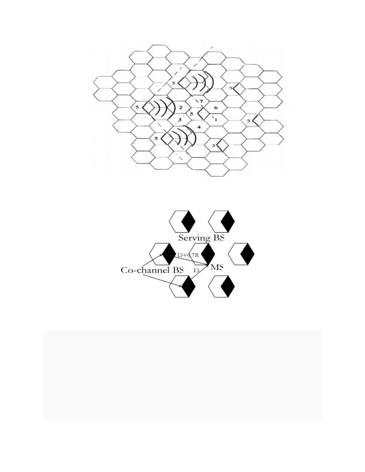
6. Describe a 1200 sectoring scheme to increase the SIR for the system. Recompute the
outage probability with the deployed sectoring.
Sectoring is the method which is used for cellular system to improve the SIR
performance; cells are divided into the radial sectors in this method. 1200 cell sectoring
reduces the first tier co- channel interferes from 6 to 2. The distance for first tier or the
outage probability will be at D and D+ 0.7R.
⊘ This is a preview!⊘
Do you want full access?
Subscribe today to unlock all pages.

Trusted by 1+ million students worldwide
PART: B
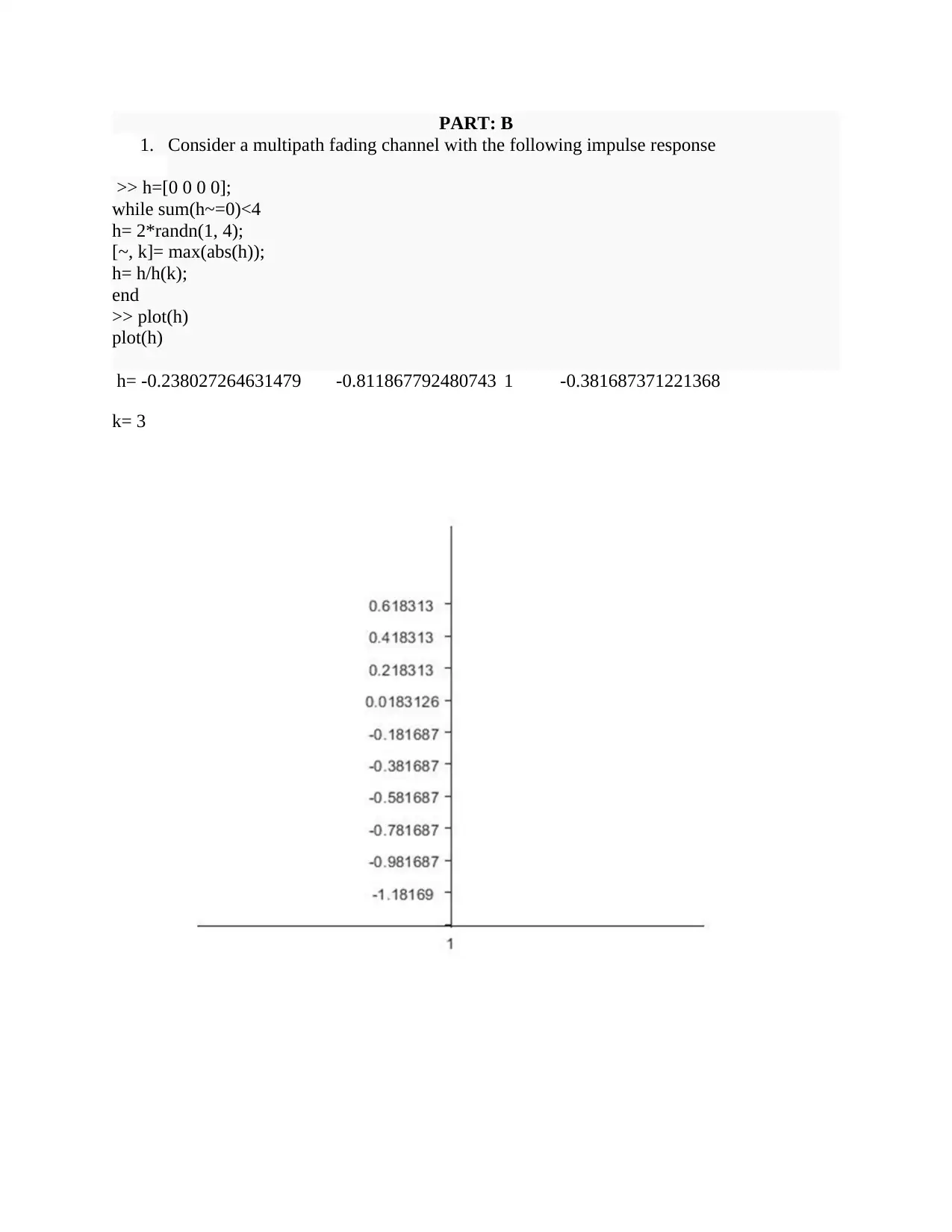
1. Consider a multipath fading channel with the following impulse response
>> h=[0 0 0 0];
while sum(h~=0)<4
h= 2*randn(1, 4);
[~, k]= max(abs(h));
h= h/h(k);
end
>> plot(h)
plot(h)
h= -0.238027264631479 -0.811867792480743 1 -0.381687371221368
k= 3
1. Consider a multipath fading channel with the following impulse response
>> h=[0 0 0 0];
while sum(h~=0)<4
h= 2*randn(1, 4);
[~, k]= max(abs(h));
h= h/h(k);
end
>> plot(h)
plot(h)
h= -0.238027264631479 -0.811867792480743 1 -0.381687371221368
k= 3
Paraphrase This Document
Need a fresh take? Get an instant paraphrase of this document with our AI Paraphraser
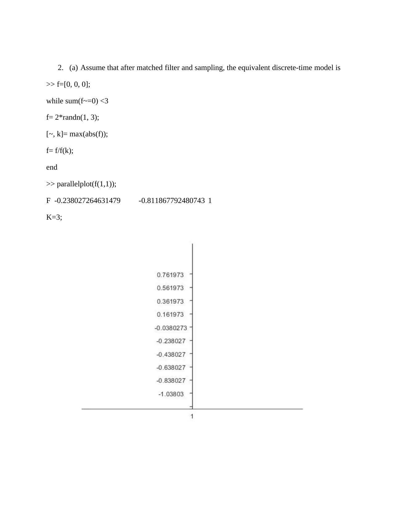
2. (a) Assume that after matched filter and sampling, the equivalent discrete-time model is
>> f=[0, 0, 0];
while sum(f~=0) <3
f= 2*randn(1, 3);
[~, k]= max(abs(f));
f= f/f(k);
end
>> parallelplot(f(1,1));
F -0.238027264631479 -0.811867792480743 1
K=3;
>> f=[0, 0, 0];
while sum(f~=0) <3
f= 2*randn(1, 3);
[~, k]= max(abs(f));
f= f/f(k);
end
>> parallelplot(f(1,1));
F -0.238027264631479 -0.811867792480743 1
K=3;
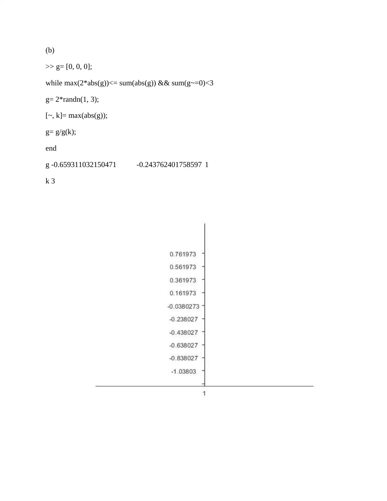
(b)
>> g= [0, 0, 0];
while max(2*abs(g))<= sum(abs(g)) && sum(g~=0)<3
g= 2*randn(1, 3);
[~, k]= max(abs(g));
g= g/g(k);
end
g -0.659311032150471 -0.243762401758597 1
k 3
>> g= [0, 0, 0];
while max(2*abs(g))<= sum(abs(g)) && sum(g~=0)<3
g= 2*randn(1, 3);
[~, k]= max(abs(g));
g= g/g(k);
end
g -0.659311032150471 -0.243762401758597 1
k 3
⊘ This is a preview!⊘
Do you want full access?
Subscribe today to unlock all pages.

Trusted by 1+ million students worldwide

3. Write the detection rule ignoring ISI. Derive the error probability of the unequalised
system.
MAP Detection Rule mˆ ⇒ mi if py|x(v|i) · px(i) ≥ py|x(v|j) · px(j) ∀ j 6= i
The decision might be assigned to message for mi or mj without providing the change in
minimized probability error, in case of holding the equality.
Maximum Likelihood detector:
If all of the transmitted messages is having the equal probability as: px(i) = 1 M ∀ i =
0, ..., M − 1 ,
So the detection rule for MAP will become:
ML Detection Rule mˆ ⇒ mi if py|x(v|i) ≥ py|x(v|j) ∀ j 6= i .
The ML detector chooses an index denoted as i for each received vector in form of y = v,
and this index depends upon the channel transition probabilities and independent from the
distribution of input.
The detector cancels the factor denoted as 1/M on both of the sides. When the input data
symbols have an equal occurrence probability, then the detector minimizes Pe.
ML detection uses the detection rule, even when the input distribution shows non-
uniform. Because it might be unknown but can be assumed as uniform. This theorem
proves the uniform assumption.
Paraphrase This Document
Need a fresh take? Get an instant paraphrase of this document with our AI Paraphraser
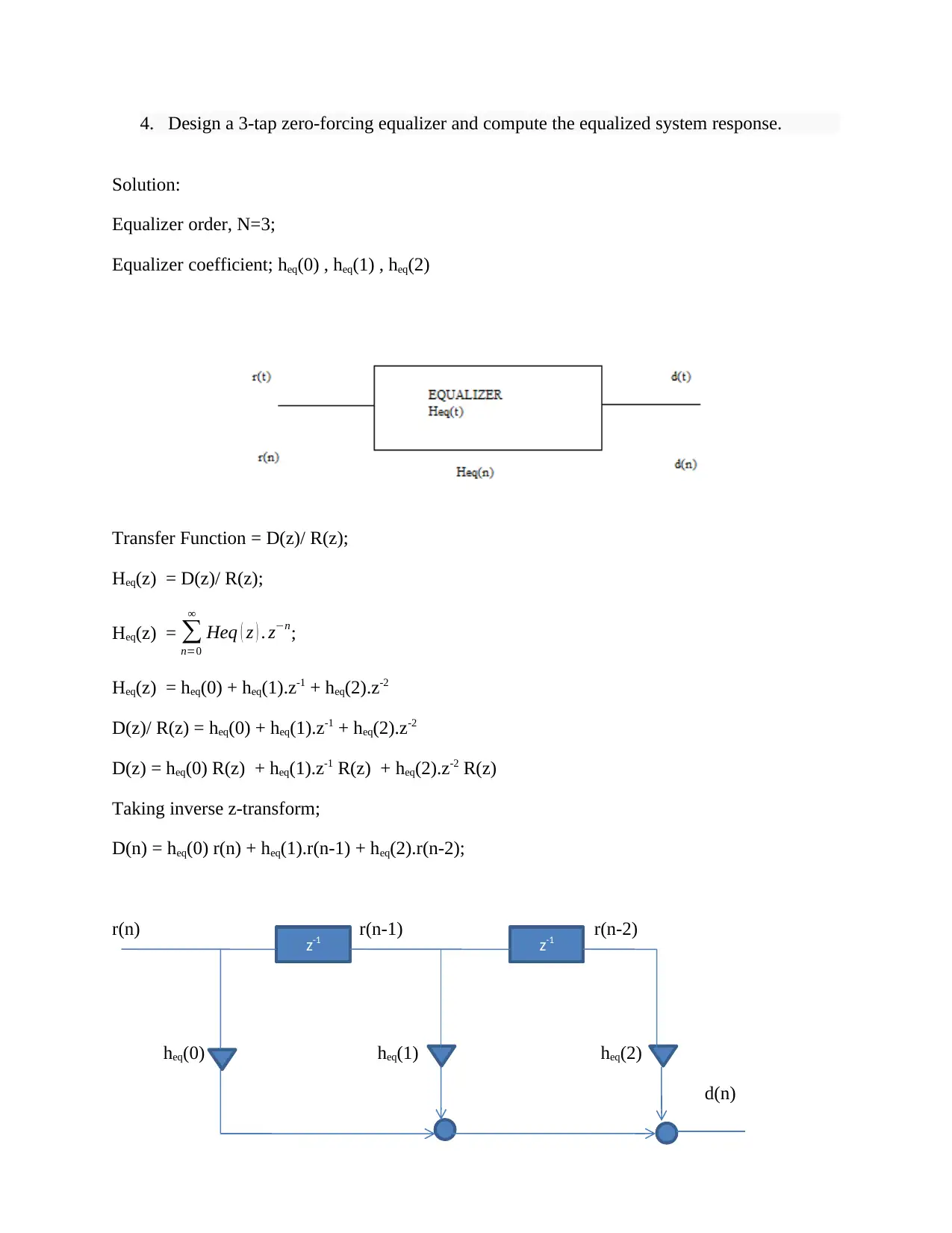
4. Design a 3-tap zero-forcing equalizer and compute the equalized system response.
Solution:
Equalizer order, N=3;
Equalizer coefficient; heq(0) , heq(1) , heq(2)
Transfer Function = D(z)/ R(z);
Heq(z) = D(z)/ R(z);
Heq(z) = ∑
n=0
∞
Heq ( z ) . z−n;
Heq(z) = heq(0) + heq(1).z-1 + heq(2).z-2
D(z)/ R(z) = heq(0) + heq(1).z-1 + heq(2).z-2
D(z) = heq(0) R(z) + heq(1).z-1 R(z) + heq(2).z-2 R(z)
Taking inverse z-transform;
D(n) = heq(0) r(n) + heq(1).r(n-1) + heq(2).r(n-2);
r(n) r(n-1) r(n-2)
heq(0) heq(1) heq(2)
d(n)
z-1 z-1
1
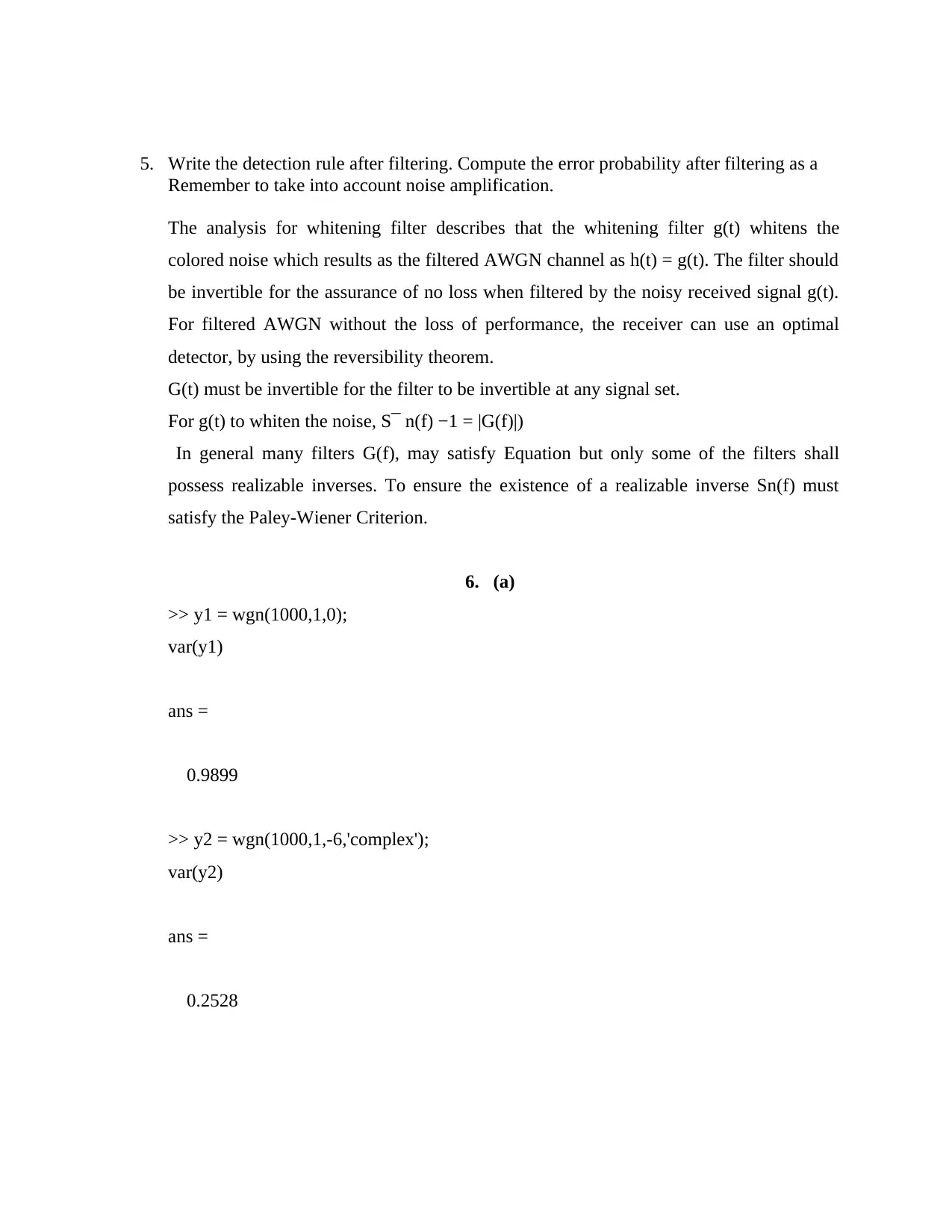
5. Write the detection rule after filtering. Compute the error probability after filtering as a
Remember to take into account noise amplification.
The analysis for whitening filter describes that the whitening filter g(t) whitens the
colored noise which results as the filtered AWGN channel as h(t) = g(t). The filter should
be invertible for the assurance of no loss when filtered by the noisy received signal g(t).
For filtered AWGN without the loss of performance, the receiver can use an optimal
detector, by using the reversibility theorem.
G(t) must be invertible for the filter to be invertible at any signal set.
For g(t) to whiten the noise, S¯ n(f) −1 = |G(f)|)
In general many filters G(f), may satisfy Equation but only some of the filters shall
possess realizable inverses. To ensure the existence of a realizable inverse Sn(f) must
satisfy the Paley-Wiener Criterion.
6. (a)
>> y1 = wgn(1000,1,0);
var(y1)
ans =
0.9899
>> y2 = wgn(1000,1,-6,'complex');
var(y2)
ans =
0.2528
⊘ This is a preview!⊘
Do you want full access?
Subscribe today to unlock all pages.

Trusted by 1+ million students worldwide
6.(b)
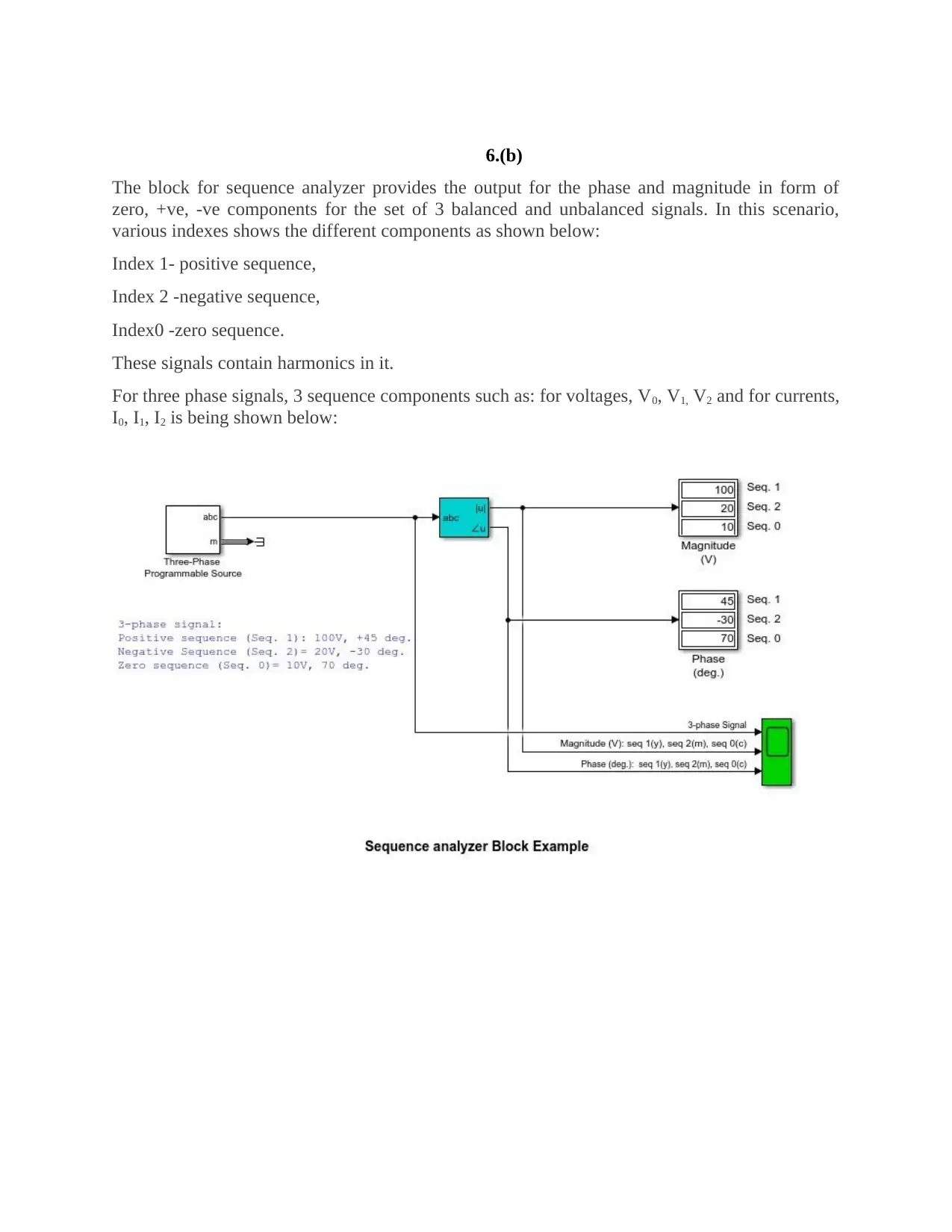
The block for sequence analyzer provides the output for the phase and magnitude in form of
zero, +ve, -ve components for the set of 3 balanced and unbalanced signals. In this scenario,
various indexes shows the different components as shown below:
Index 1- positive sequence,
Index 2 -negative sequence,
Index0 -zero sequence.
These signals contain harmonics in it.
For three phase signals, 3 sequence components such as: for voltages, V0, V1, V2 and for currents,
I0, I1, I2 is being shown below:
Paraphrase This Document
Need a fresh take? Get an instant paraphrase of this document with our AI Paraphraser
6.(c)
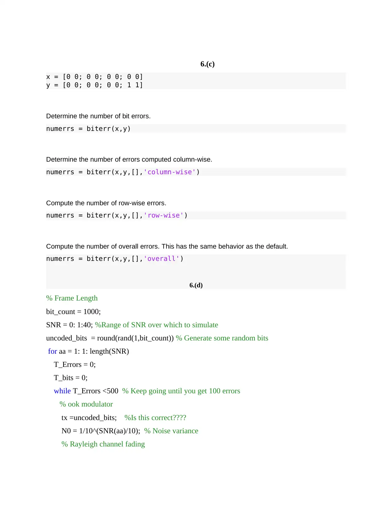
x = [0 0; 0 0; 0 0; 0 0]
y = [0 0; 0 0; 0 0; 1 1]
Determine the number of bit errors.
numerrs = biterr(x,y)
Determine the number of errors computed column-wise.
numerrs = biterr(x,y,[],'column-wise')
Compute the number of row-wise errors.
numerrs = biterr(x,y,[],'row-wise')
Compute the number of overall errors. This has the same behavior as the default.
numerrs = biterr(x,y,[],'overall')
6.(d)
% Frame Length
bit_count = 1000;
SNR = 0: 1:40; %Range of SNR over which to simulate
uncoded_bits = round(rand(1,bit_count)) % Generate some random bits
for aa = 1: 1: length(SNR)
T_Errors = 0;
T_bits = 0;
while T_Errors <500 % Keep going until you get 100 errors
% ook modulator
tx =uncoded_bits; %Is this correct????
N0 = 1/10^(SNR(aa)/10); % Noise variance
% Rayleigh channel fading
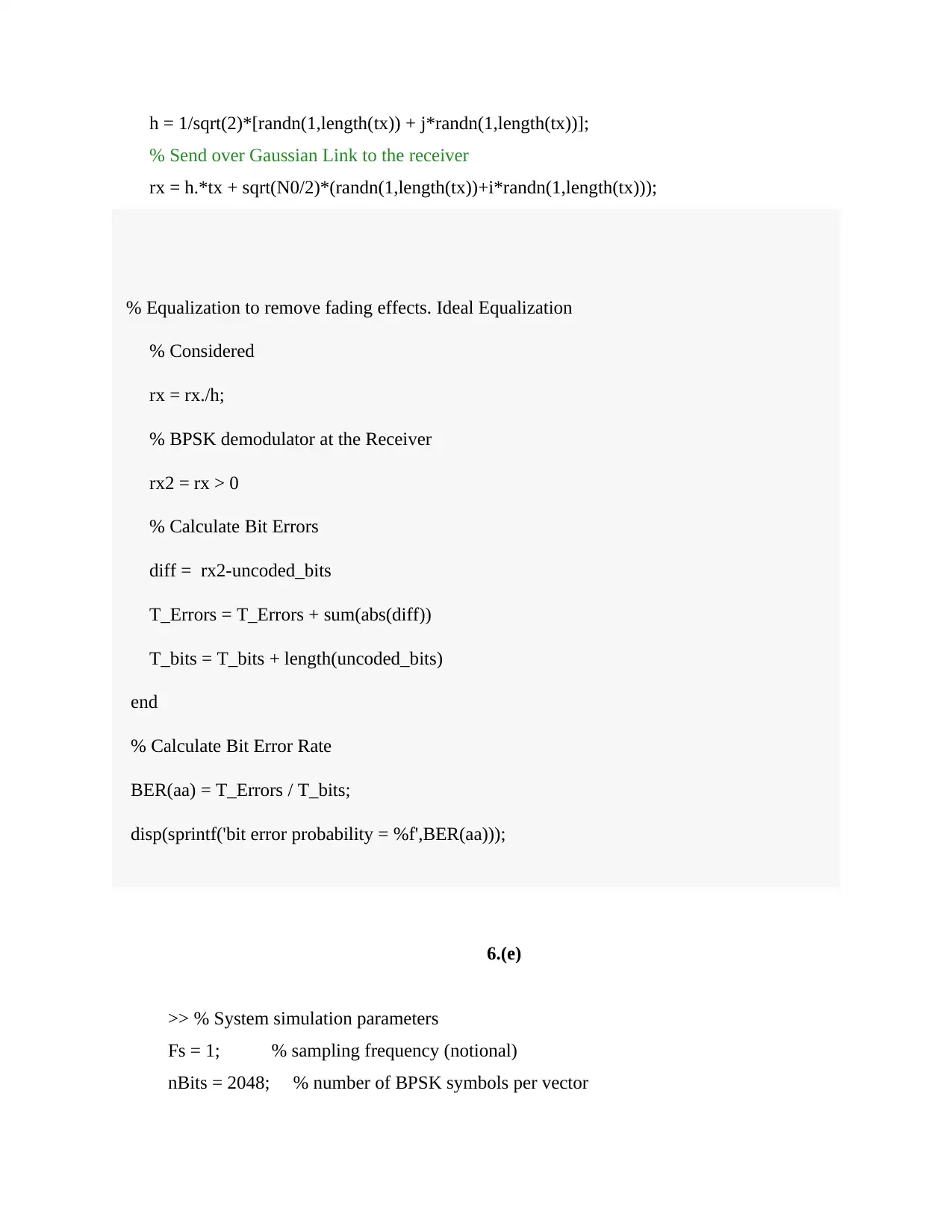
h = 1/sqrt(2)*[randn(1,length(tx)) + j*randn(1,length(tx))];
% Send over Gaussian Link to the receiver
rx = h.*tx + sqrt(N0/2)*(randn(1,length(tx))+i*randn(1,length(tx)));
% Equalization to remove fading effects. Ideal Equalization
% Considered
rx = rx./h;
% BPSK demodulator at the Receiver
rx2 = rx > 0
% Calculate Bit Errors
diff = rx2-uncoded_bits
T_Errors = T_Errors + sum(abs(diff))
T_bits = T_bits + length(uncoded_bits)
end
% Calculate Bit Error Rate
BER(aa) = T_Errors / T_bits;
disp(sprintf('bit error probability = %f',BER(aa)));
6.(e)
>> % System simulation parameters
Fs = 1; % sampling frequency (notional)
nBits = 2048; % number of BPSK symbols per vector
⊘ This is a preview!⊘
Do you want full access?
Subscribe today to unlock all pages.

Trusted by 1+ million students worldwide
1 out of 15
Your All-in-One AI-Powered Toolkit for Academic Success.
+13062052269
info@desklib.com
Available 24*7 on WhatsApp / Email
![[object Object]](/_next/static/media/star-bottom.7253800d.svg)
Unlock your academic potential
Copyright © 2020–2026 A2Z Services. All Rights Reserved. Developed and managed by ZUCOL.