Mobile Robotics: Kinematics Models, IST Portugal, 2002
VerifiedAdded on 2021/10/01
|16
|2041
|182
Homework Assignment
AI Summary
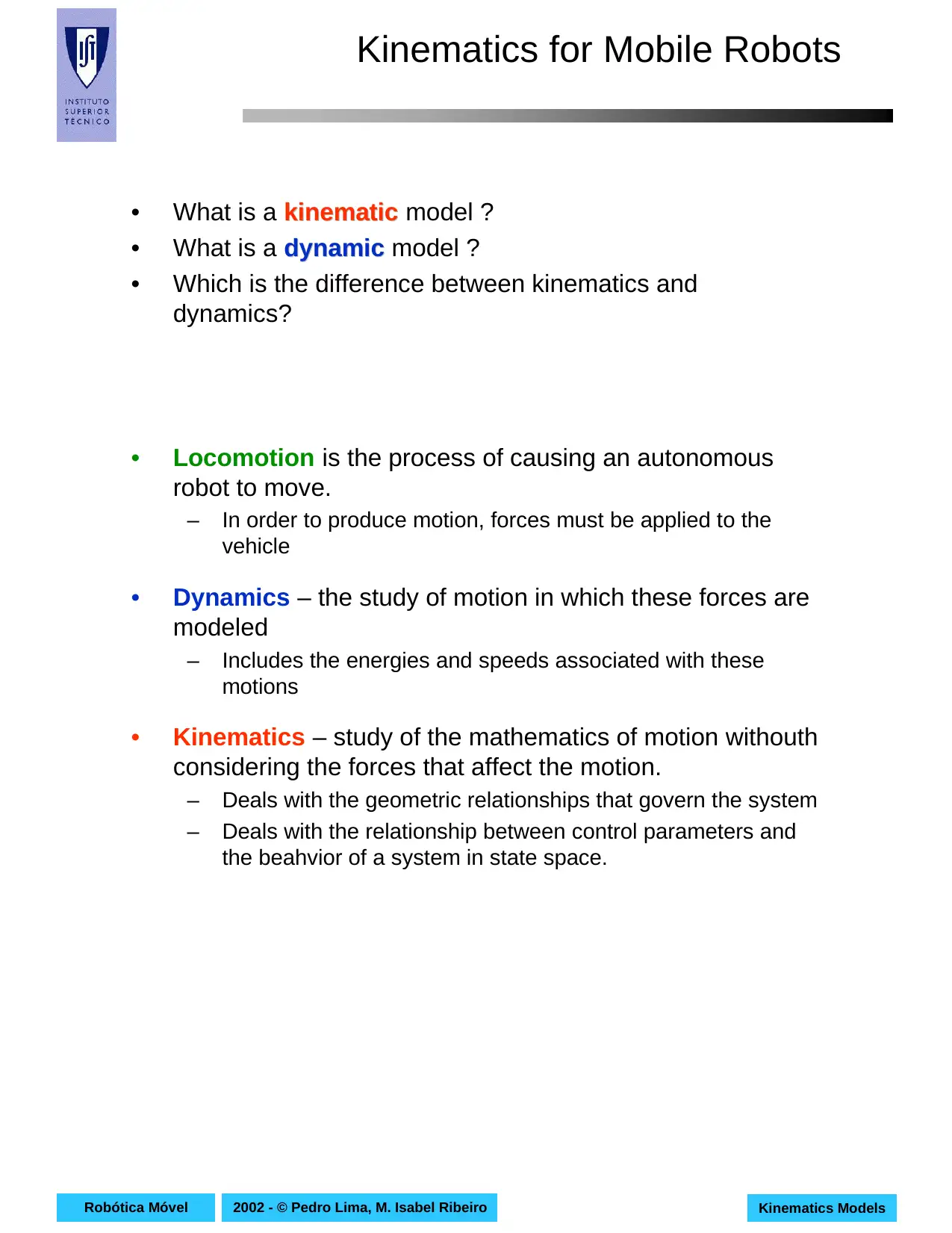
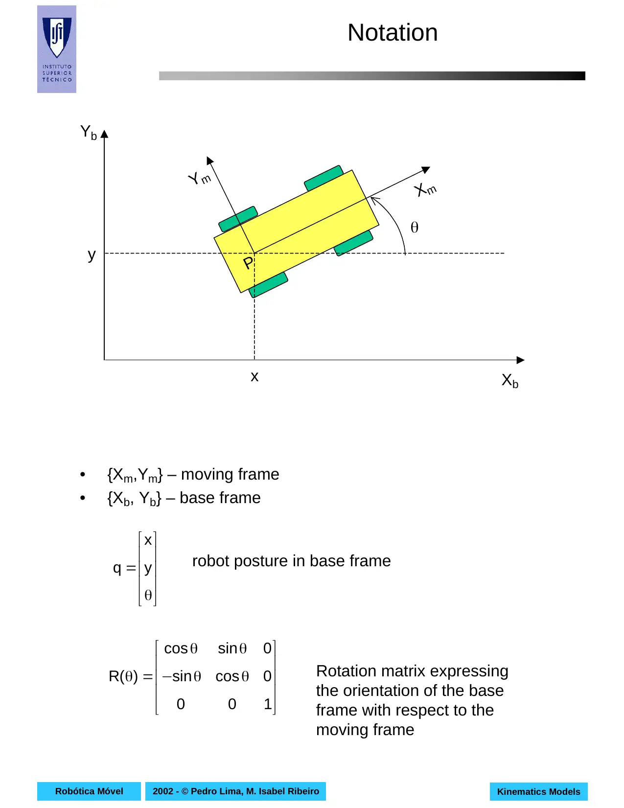
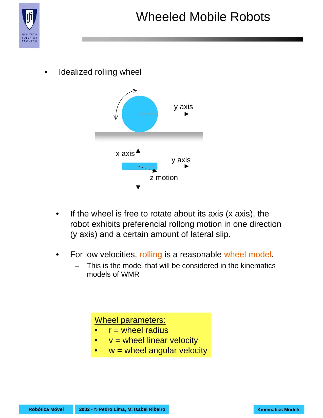
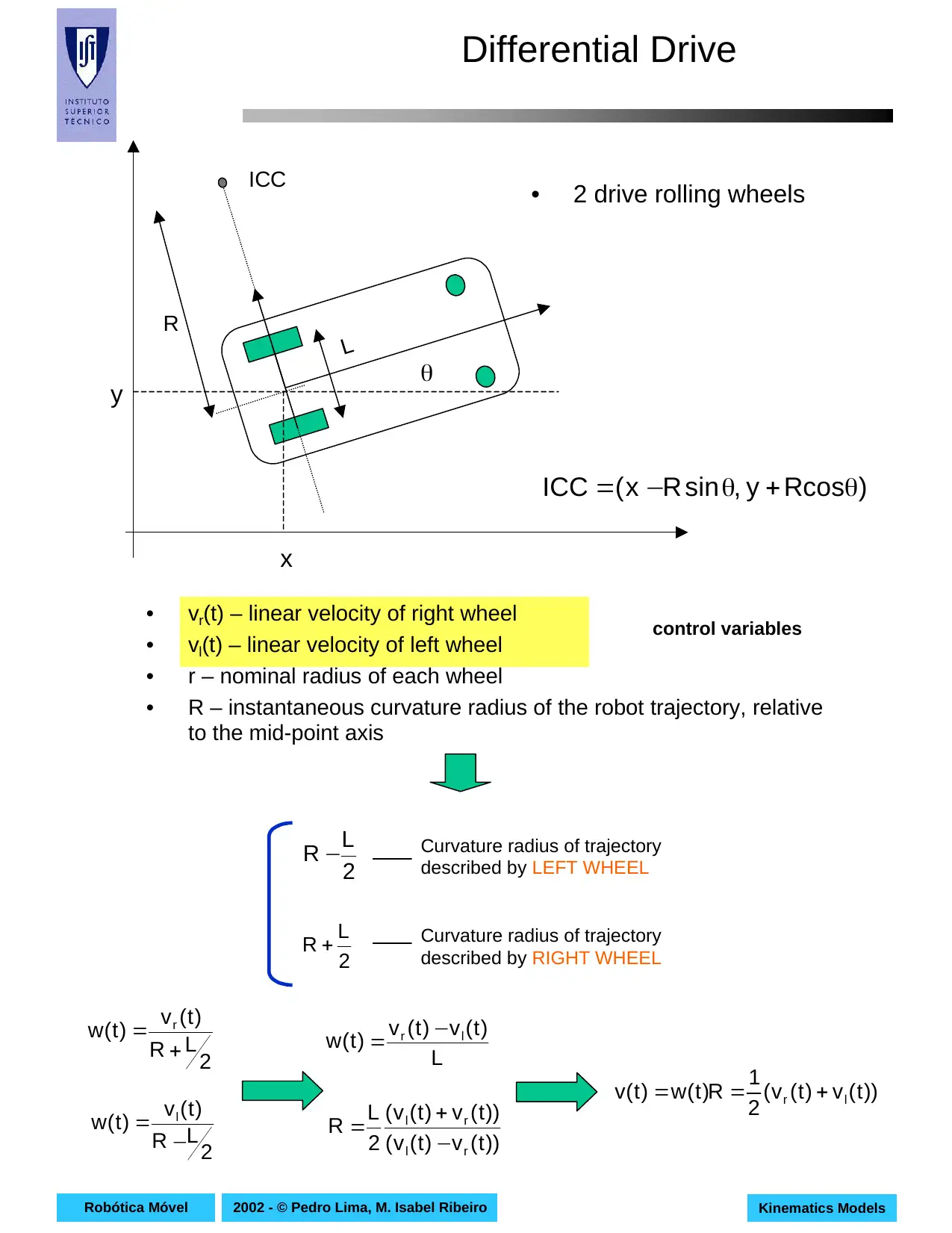
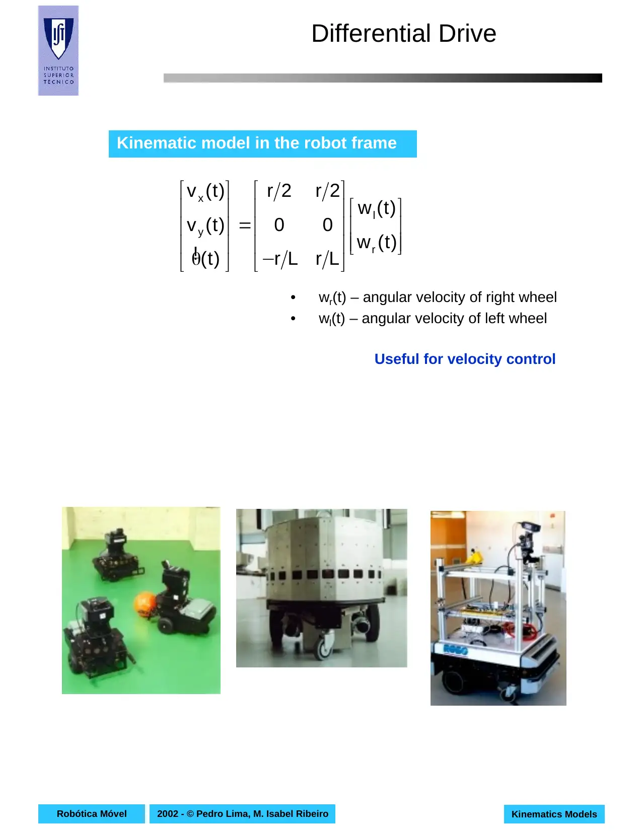
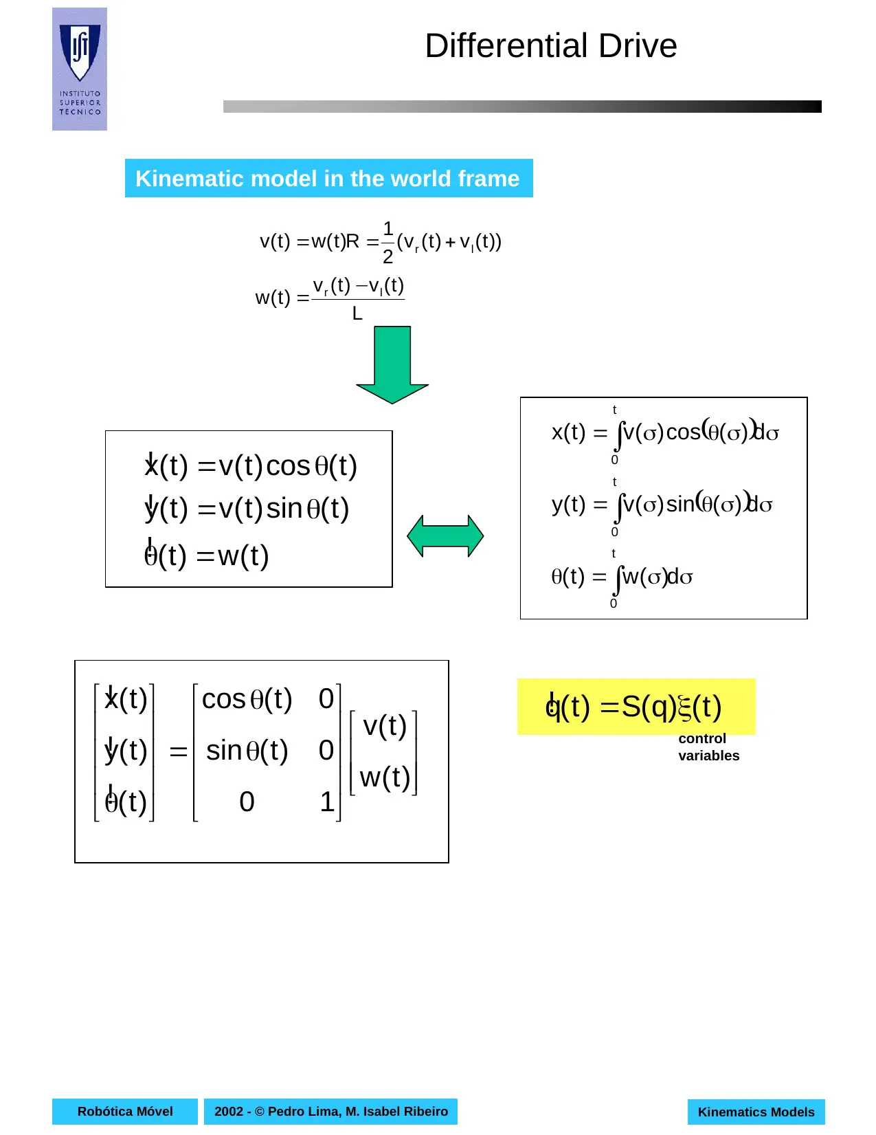
This document presents a comprehensive overview of kinematics models for mobile robots, focusing on the mathematical relationships governing their motion without considering the forces involved. It begins by defining kinematics and its distinction from dynamics, emphasizing the importance of these models in understanding robot locomotion. The paper then delves into specific kinematic models for wheeled mobile robots, including differential drive, synchronous drive, tricycle, and omnidirectional robots. For each model, the document provides detailed explanations, diagrams, equations, and control variables, including the kinematic models in both the robot frame and the world frame, along with particular cases and applications. The content references key concepts like the instantaneous center of curvature (ICC) and explores how different configurations affect robot movement, making it a valuable resource for students in robotics and related fields. The document offers a deep dive into the mathematical and geometric principles underlying mobile robot movement and control.

2002 - © Pedro Lima, M. Isabel RibeiroRobótica Móvel Kinematics Models
KINEMATICS MODELS OFKINEMATICS MODELS OF
MOBILE ROBOTSMOBILE ROBOTS
Maria Isabel Ribeiro
Pedro Lima
mir@isr.ist.utl.pt pal@isr.ist.utl.pt
Instituto Superior Técnico (IST)
Instituto de Sistemas e Robótica (ISR)
Av.Rovisco Pais, 1
1049-001 Lisboa
PORTUGAL
April.2002
All the rights reserved
MOBILE ROBOTICS course
Secure Best Marks with AI Grader
Need help grading? Try our AI Grader for instant feedback on your assignments.

2002 - © Pedro Lima, M. Isabel RibeiroRobótica Móvel Kinematics Models
References
• Gregory Dudek, Michael Jenkin, “Computational Principles of
Mobile Robotics”, Cambridge University Press, 2000 (Chapter 1).
• Carlos Canudas de Wit, Bruno Siciliano, Georges Bastin (eds),
“Theory of Robot Control”, Springer 1996.
References
• Gregory Dudek, Michael Jenkin, “Computational Principles of
Mobile Robotics”, Cambridge University Press, 2000 (Chapter 1).
• Carlos Canudas de Wit, Bruno Siciliano, Georges Bastin (eds),
“Theory of Robot Control”, Springer 1996.

2002 - © Pedro Lima, M. Isabel RibeiroRobótica Móvel Kinematics Models
Kinematics for Mobile Robots
• What is a kinematickinematic model ?
• What is a dynamicdynamic model ?
• Which is the difference between kinematics and
dynamics?
• Locomotion is the process of causing an autonomous
robot to move.
– In order to produce motion, forces must be applied to the
vehicle
• Dynamics – the study of motion in which these forces are
modeled
– Includes the energies and speeds associated with these
motions
• Kinematics – study of the mathematics of motion withouth
considering the forces that affect the motion.
– Deals with the geometric relationships that govern the system
– Deals with the relationship between control parameters and
the beahvior of a system in state space.

2002 - © Pedro Lima, M. Isabel RibeiroRobótica Móvel Kinematics Models
Notation
• {Xm,Ym} – moving frame
• {Xb, Yb} – base frame
Xm
Ym
P
Xb
Yb
x
y
θ
θ
= y
x
q robot posture in base frame
θθ−
θθ
=θ
100
0cossin
0sincos
)(R Rotation matrix expressing
the orientation of the base
frame with respect to the
moving frame
Notation
• {Xm,Ym} – moving frame
• {Xb, Yb} – base frame
Xm
Ym
P
Xb
Yb
x
y
θ
θ
= y
x
q robot posture in base frame
θθ−
θθ
=θ
100
0cossin
0sincos
)(R Rotation matrix expressing
the orientation of the base
frame with respect to the
moving frame
Secure Best Marks with AI Grader
Need help grading? Try our AI Grader for instant feedback on your assignments.

2002 - © Pedro Lima, M. Isabel RibeiroRobótica Móvel Kinematics Models
Wheeled Mobile Robots
• Idealized rolling wheel
y axis
y axis
x axis
z motion
• If the wheel is free to rotate about its axis (x axis), the
robot exhibits preferencial rollong motion in one direction
(y axis) and a certain amount of lateral slip.
• For low velocities, rolling is a reasonable wheel model.
– This is the model that will be considered in the kinematics
models of WMR
Wheel parameters:
• r = wheel radius
• v = wheel linear velocity
• w = wheel angular velocity

2002 - © Pedro Lima, M. Isabel RibeiroRobótica Móvel Kinematics Models
Differential Drive
• vr(t) – linear velocity of right wheel
• vl(t) – linear velocity of left wheel
• r – nominal radius of each wheel
• R – instantaneous curvature radius of the robot trajectory, relative
to the mid-point axis
L
R
ICC
x
y θ
2
L
R −
2
L
R +
Curvature radius of trajectory
described by LEFT WHEEL
Curvature radius of trajectory
described by RIGHT WHEEL
2
LR
)t(v
)t(w r
+
=
2
LR
)t(v
)t(w l
−
=
L
)t(v)t(v
)t(w lr −
=
))t(v)t(v(
))t(v)t(v(
2
L
R
rl
rl
−
+
=
))t(v)t(v(
2
1
R)t(w)t(v lr +==
• 2 drive rolling wheels
)Rcosy,sinRx(ICC θ+θ−=
control variables

2002 - © Pedro Lima, M. Isabel RibeiroRobótica Móvel Kinematics Models
Differential Drive
• Kinematic model in the robot frame
−
=
θ )t(w
)t(w
LrLr
00
2r2r
)t(
)t(v
)t(v
r
l
y
x
!
• wr(t) – angular velocity of right wheel
• wl(t) – angular velocity of left wheel
Useful for velocity control
Differential Drive
• Kinematic model in the robot frame
−
=
θ )t(w
)t(w
LrLr
00
2r2r
)t(
)t(v
)t(v
r
l
y
x
!
• wr(t) – angular velocity of right wheel
• wl(t) – angular velocity of left wheel
Useful for velocity control
Paraphrase This Document
Need a fresh take? Get an instant paraphrase of this document with our AI Paraphraser

2002 - © Pedro Lima, M. Isabel RibeiroRobótica Móvel Kinematics Models
Differential Drive
θ
θ
=
θ )t(w
)t(v
10
0)t(sin
0)t(cos
)t(
)t(y
)t(x
!
!
! )t()q(S)t(q ξ=!
control
variables
))t(v)t(v(
2
1
R)t(w)t(v lr +==
( )
( )
σσ=θ
σσθσ=
σσθσ=
∫
∫
∫
d)(w)t(
d)(sin)(v)t(y
d)(cos)(v)t(x
t
0
t
0
t
0
L
)t(v)t(v
)t(w lr −
=
)t(w)t(
)t(sin)t(v)t(y
)t(cos)t(v)t(x
=θ
θ=
θ=
!
!
!
Kinematic model in the world frame

2002 - © Pedro Lima, M. Isabel RibeiroRobótica Móvel Kinematics Models
Differential Drive
• Particular cases:
– vl(t)=vr(t)
• Straight line trajectory
– vl(t)=-vr(t)
• Circular path with ICC (instantaneous center of curvature) on
the mid-point between drive wheels
.cte)t(0)t(0)t(w
)t(v)t(v)t(v lr
=θ⇒=θ⇒=
==
!
)t(v
L
2
)t(w
0)t(v
R=
=
Differential Drive
• Particular cases:
– vl(t)=vr(t)
• Straight line trajectory
– vl(t)=-vr(t)
• Circular path with ICC (instantaneous center of curvature) on
the mid-point between drive wheels
.cte)t(0)t(0)t(w
)t(v)t(v)t(v lr
=θ⇒=θ⇒=
==
!
)t(v
L
2
)t(w
0)t(v
R=
=

2002 - © Pedro Lima, M. Isabel RibeiroRobótica Móvel Kinematics Models
Synchronous drive
• In a synchronous drive robot (synchro drive) each wheel is
capable of being driven and steered.
• Typical configurations
– Three steered wheels arranged as vertices of an equilateral
triangle often surmounted by a cylindrical platform
– All the wheels turn and drive in unison
• This leads to a holonomic behavior
• Steered wheel
– The orientation of the rotation axis can be controlled
y axis
Secure Best Marks with AI Grader
Need help grading? Try our AI Grader for instant feedback on your assignments.

2002 - © Pedro Lima, M. Isabel RibeiroRobótica Móvel Kinematics Models
Synchronous drive
• All the wheels turn in unison
• All of the three wheels point in the same direction and turn
at the same rate
– This is typically achieved through the use of a complex
collection of belts that physically link the wheels together
• The vehicle controls the direction in which the wheels point
and the rate at which they roll
• Because all the wheels remain parallel the synchro drive
always rotate about the center of the robot
• The synchro drive robot has the ability to control the
orientation θ of their pose diretly.
• Control variables (independent)
– v(t), w(t)
• The ICC is always at infinity
• Changing the orientation of the wheels
manipulates the direction of ICC
( )
( )
σσ=θ
σσθσ=
σσθσ=
∫
∫
∫
d)(w)t(
d)(sin)(v)t(y
d)(cos)(v)t(x
t
0
t
0
t
0

2002 - © Pedro Lima, M. Isabel RibeiroRobótica Móvel Kinematics Models
Synchronous Drive
• Particular cases:
– v(t)=0, w(t)=w=cte. during a time interval
• The robot rotates in place by an amount
– v(t)=v, w(t)=0 during a time interval
• The robot moves in the direction its pointing a distance
t∆
tw ∆
t∆
tv ∆
Synchronous Drive
• Particular cases:
– v(t)=0, w(t)=w=cte. during a time interval
• The robot rotates in place by an amount
– v(t)=v, w(t)=0 during a time interval
• The robot moves in the direction its pointing a distance
t∆
tw ∆
t∆
tv ∆

2002 - © Pedro Lima, M. Isabel RibeiroRobótica Móvel Kinematics Models
Tricycle
• Three wheels and odometers on the two rear wheels
• Steering and power are provided through the front wheel
• control variables:
– steering direction α(t)
– angular velocity of steering wheel ws(t)
ICC ICC
The ICC must lie on
the line that passes
through, and is
perpendicular to, the
fixed rear wheels
R
Paraphrase This Document
Need a fresh take? Get an instant paraphrase of this document with our AI Paraphraser

2002 - © Pedro Lima, M. Isabel RibeiroRobótica Móvel Kinematics Models
Tricycle
If the steering wheel is set to
an angle α(t) from the
straight-line direction, the
tricycle will rotate with
angular velocity w(t) about a
point lying a distance R along
the line perpendicular to and
passing through the rear
wheels.
d
x
y θ
α
R
( ))t(
2
tgd)t(R α−π=
22
s
)t(Rd
r)t(w
)t(w +
=
Xb
Yb
r = steering wheel radius
angular velocity of the moving frame
relative to the base frame
r)t(w)t(v ss = linear velocity of steering wheel
)t(sin
d
)t(v
)t(w s α=

2002 - © Pedro Lima, M. Isabel RibeiroRobótica Móvel Kinematics Models
Tricycle
Kinematic model in the robot frame
Kinematic model in the world frame
)t(sin
d
)t(v
)t(
)t(sin)t(cos)t(v)t(y
)t(cos)t(cos)t(v)t(x
s
s
s
α=θ
θα=
θα=
!
!
!
)t(sin
d
)t(v
)t(
0)t(v
)t(cos)t(v)t(v
s
y
sx
α=θ
=
α=
!
with no splippage
)t(sin
d
)t(v
)t(w
)t(cos)t(v)t(v
s
s
α=
α=
θ
θ
=
θ )t(w
)t(v
10
0)t(sin
0)t(cos
)t(
)t(y
)t(x
!
!
!

2002 - © Pedro Lima, M. Isabel RibeiroRobótica Móvel Kinematics Models
Omnidireccional
Xm
Yf
θ
30º
1
23
L Ym
Xf
−
−
=
θ 3
2
1
y
x
w
w
w
L3
r
L3
r
L3
r
r
3
1
r
3
1
r
3
2
r
3
1
r
3
1
0
V
V
!
Kinematic model in the robot frame
w1, w2, w3 – angular
velocities of the three
swedish wheels
Swedish wheel
Omnidireccional
Xm
Yf
θ
30º
1
23
L Ym
Xf
−
−
=
θ 3
2
1
y
x
w
w
w
L3
r
L3
r
L3
r
r
3
1
r
3
1
r
3
2
r
3
1
r
3
1
0
V
V
!
Kinematic model in the robot frame
w1, w2, w3 – angular
velocities of the three
swedish wheels
Swedish wheel
1 out of 16

Your All-in-One AI-Powered Toolkit for Academic Success.
+13062052269
info@desklib.com
Available 24*7 on WhatsApp / Email
Unlock your academic potential
© 2024 | Zucol Services PVT LTD | All rights reserved.