Faculty of Computing: Design Study of a Smart Collaborative Robot
VerifiedAdded on 2022/09/07
|23
|4209
|19
Report
AI Summary
This report details the model-based system engineering of a smart collaborative robot designed for palletizing tasks. The project encompasses the integration of vision, voice control, and IoT capabilities to enhance the robot's functionality and safety. The report begins with an introduction to collaborative robots and their applications, followed by a literature review of relevant technologies and methodologies. It then outlines the project's objectives, including the development of obstacle detection, pathfinding using the A* algorithm, and the design of a gripper system. The methodology section describes the application of Model Based Systems Engineering (MBSE) for the design process, utilizing SysML diagrams and other tools for requirements specification, design specification, and the creation of block definition diagrams. The results and analysis section provides insights into obstacle detection techniques, including pre-processing, feature detection, and object classification, as well as the implementation of the A* algorithm for path planning. The report concludes with a summary of the findings and a discussion of potential future work.

Model Based System Engineering Of a Smart Collaborative Robot with Vision, Voice and IoT Capabilities
Paraphrase This Document
Need a fresh take? Get an instant paraphrase of this document with our AI Paraphraser
Table of Contents
Introduction......................................................................................................................................2
Aim & Objectives............................................................................................................................2
Literature Review............................................................................................................................3
Methodology....................................................................................................................................4
Requirements Specification.............................................................................................................5
Design Specification........................................................................................................................7
Design Concept and Final Design...................................................................................................9
Results and Analysis......................................................................................................................11
Obstacle detection......................................................................................................................11
Path finding using A* algorithm................................................................................................14
Conclusion.....................................................................................................................................20
References......................................................................................................................................21
1
Introduction
A 1995 research mission (General Motors Foundation) was the basic foundation of the
collaborative robots. The main target of the mission was to devise a method which would enable
the robots (or equipment resembling robots) to work with the humans in their specific
environments in a highly safe manner. Crucial robotic manufacturers (in the collaborative
market) such as KUKA, FANUC, Universal Robots, Motoman and ABB are continuously
working towards the development of responsive and smart robots. Along with making certain
improvements in the functionality of the app, the collaborative robotics movement is also
lowering down the required space in respect to a robotic unit. Numerous benefits are being
offered to the production lines, business houses as well as workers by the collaborative
technology [6]. Cobots have the capability of undertaking varied roles across different industries
as well as operating in almost all work environments along with human beings. Apart from this,
these collaborative machines are also capable of performing numerous tasks like commodity
packing, assembling, palletizing and others.
Aim & Objectives
This project deals with the development of a sharp, collective palletizing robot (in respect
to the manufacturing industry) who has the potential of working along with human beings. So
“safety of humans” must be an important component of the robot’s design. For this, features such
as voice-control, vision, IoT are crucial. Below we are going to mention some activities
(project’s objectives) which are crucial to be undertaken for the achievement of the above
discussed aim.
• Undertake the primary study in respect to the collaborative robot.
• Gather crucial info in regards to collaborative robot.
• Undertake the literature review
• Performance of the design creation process
• Performance of the substitute process of examination and selection
2
⊘ This is a preview!⊘
Do you want full access?
Subscribe today to unlock all pages.
Trusted by 1+ million students worldwide
• Undertaking the task of design development and duplication
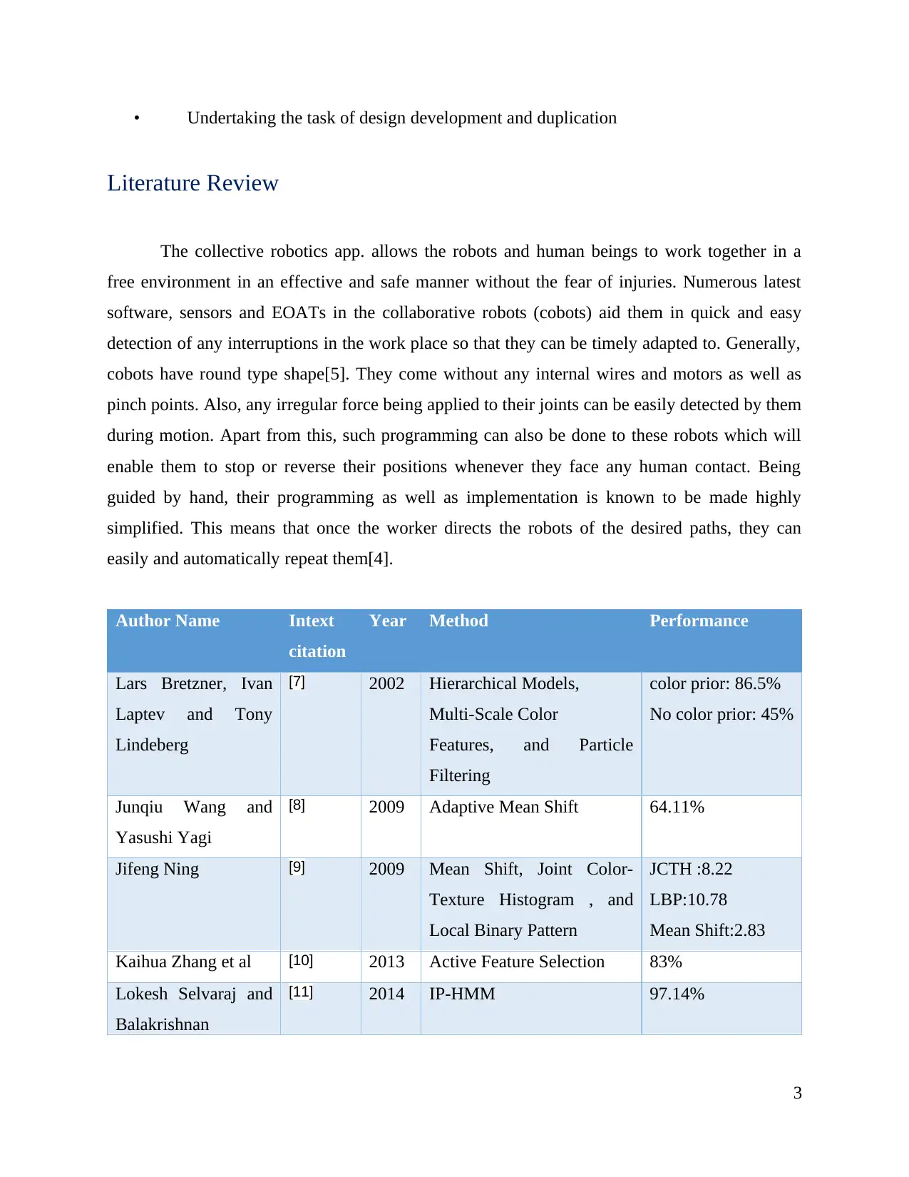
Literature Review
The collective robotics app. allows the robots and human beings to work together in a
free environment in an effective and safe manner without the fear of injuries. Numerous latest
software, sensors and EOATs in the collaborative robots (cobots) aid them in quick and easy
detection of any interruptions in the work place so that they can be timely adapted to. Generally,
cobots have round type shape[5]. They come without any internal wires and motors as well as
pinch points. Also, any irregular force being applied to their joints can be easily detected by them
during motion. Apart from this, such programming can also be done to these robots which will
enable them to stop or reverse their positions whenever they face any human contact. Being
guided by hand, their programming as well as implementation is known to be made highly
simplified. This means that once the worker directs the robots of the desired paths, they can
easily and automatically repeat them[4].
Author Name Intext
citation
Year Method Performance
Lars Bretzner, Ivan
Laptev and Tony
Lindeberg
[7] 2002 Hierarchical Models,
Multi-Scale Color
Features, and Particle
Filtering
color prior: 86.5%
No color prior: 45%
Junqiu Wang and
Yasushi Yagi
[8] 2009 Adaptive Mean Shift 64.11%
Jifeng Ning [9] 2009 Mean Shift, Joint Color-
Texture Histogram , and
Local Binary Pattern
JCTH :8.22
LBP:10.78
Mean Shift:2.83
Kaihua Zhang et al [10] 2013 Active Feature Selection 83%
Lokesh Selvaraj and
Balakrishnan
[11] 2014 IP-HMM 97.14%
3
Paraphrase This Document
Need a fresh take? Get an instant paraphrase of this document with our AI Paraphraser
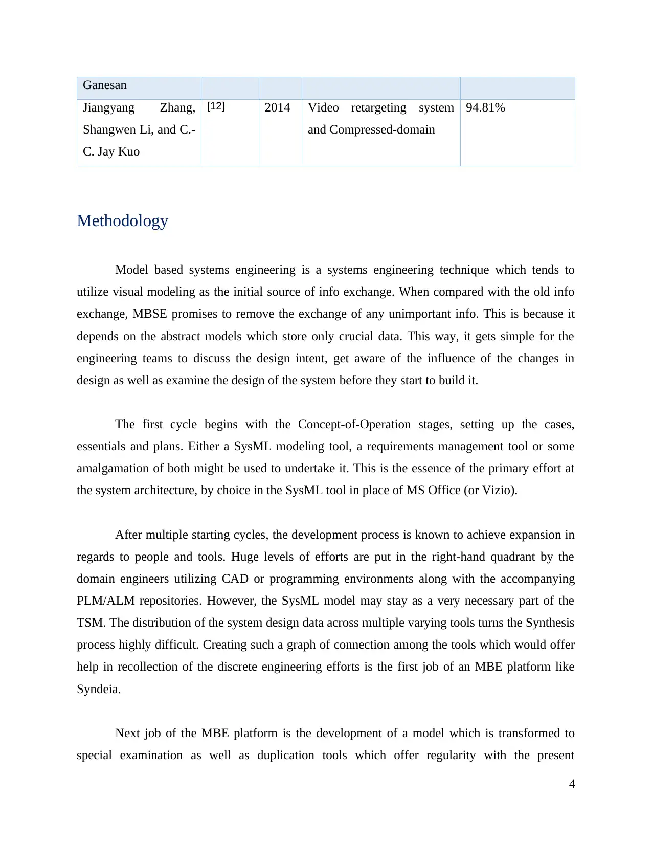
Ganesan
Jiangyang Zhang,
Shangwen Li, and C.-
C. Jay Kuo
[12] 2014 Video retargeting system
and Compressed-domain
94.81%
Methodology
Model based systems engineering is a systems engineering technique which tends to
utilize visual modeling as the initial source of info exchange. When compared with the old info
exchange, MBSE promises to remove the exchange of any unimportant info. This is because it
depends on the abstract models which store only crucial data. This way, it gets simple for the
engineering teams to discuss the design intent, get aware of the influence of the changes in
design as well as examine the design of the system before they start to build it.
The first cycle begins with the Concept-of-Operation stages, setting up the cases,
essentials and plans. Either a SysML modeling tool, a requirements management tool or some
amalgamation of both might be used to undertake it. This is the essence of the primary effort at
the system architecture, by choice in the SysML tool in place of MS Office (or Vizio).
After multiple starting cycles, the development process is known to achieve expansion in
regards to people and tools. Huge levels of efforts are put in the right-hand quadrant by the
domain engineers utilizing CAD or programming environments along with the accompanying
PLM/ALM repositories. However, the SysML model may stay as a very necessary part of the
TSM. The distribution of the system design data across multiple varying tools turns the Synthesis
process highly difficult. Creating such a graph of connection among the tools which would offer
help in recollection of the discrete engineering efforts is the first job of an MBE platform like
Syndeia.
Next job of the MBE platform is the development of a model which is transformed to
special examination as well as duplication tools which offer regularity with the present
4
synthesized TSM. The last job of the MBE platform is to bring the simulation and examination
outcomes inside the V&V quadrant so as to give a picture of the system development’s ongoing
position.
With the advancement of the system development, extra tools and people are added up in
the process. More comprehensive designs and thoroughly authenticate interpretations are made.
This is followed up by the execution of the non-digital activities related to building,
incorporation and testing. At this point, the MBE Wheel takes the image of an onion consisting
of multiple layers. This leads to a rise in the expectations on the MBE platform. In place of
creating new analysis models, consideration should be given to the fact that the framework is
capable of comparing the current models and improving them as needed. The growth of
connections is posing a huge challenge in regards to efficient tracking of links across the TSM.
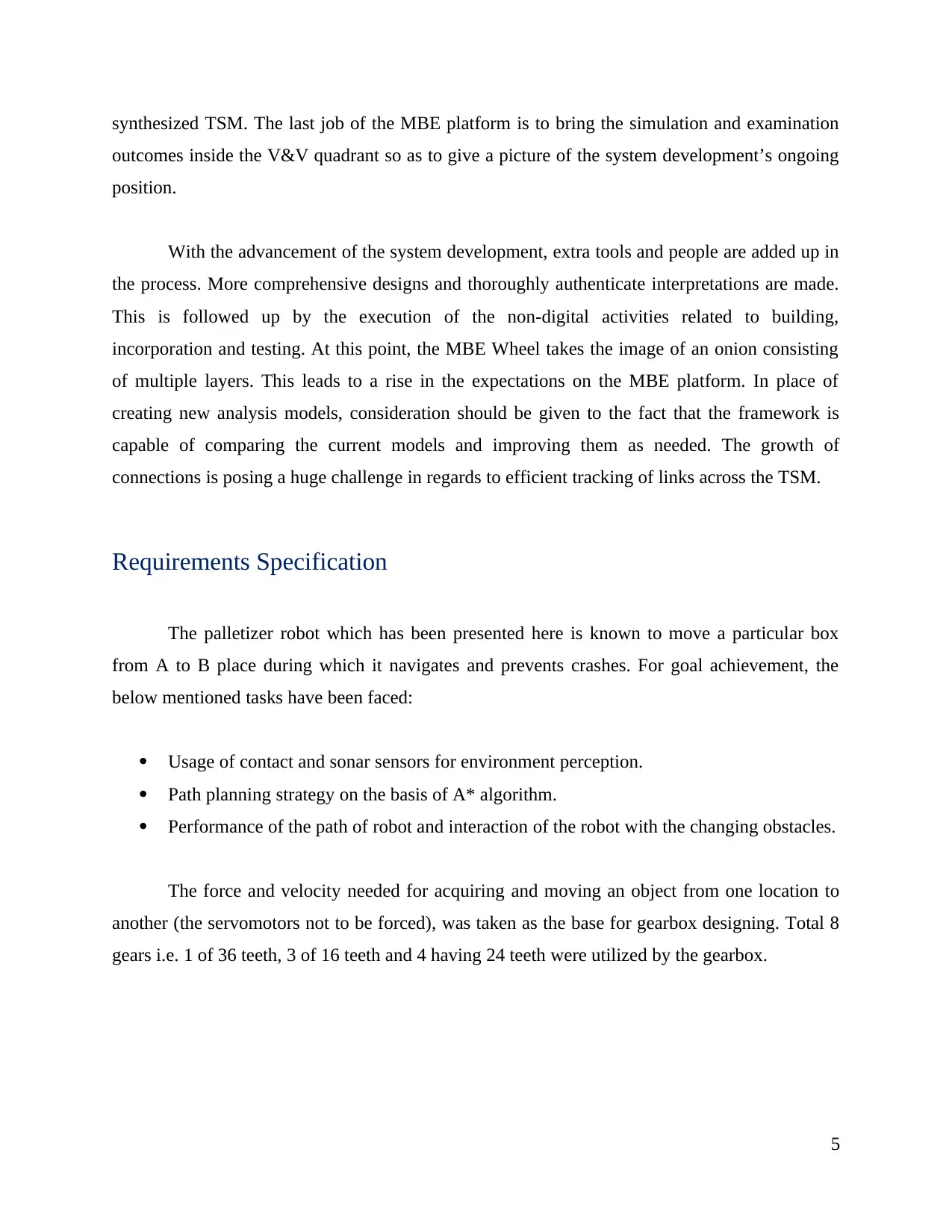
Requirements Specification
The palletizer robot which has been presented here is known to move a particular box
from A to B place during which it navigates and prevents crashes. For goal achievement, the
below mentioned tasks have been faced:
Usage of contact and sonar sensors for environment perception.
Path planning strategy on the basis of A* algorithm.
Performance of the path of robot and interaction of the robot with the changing obstacles.
The force and velocity needed for acquiring and moving an object from one location to
another (the servomotors not to be forced), was taken as the base for gearbox designing. Total 8
gears i.e. 1 of 36 teeth, 3 of 16 teeth and 4 having 24 teeth were utilized by the gearbox.
5
outcomes inside the V&V quadrant so as to give a picture of the system development’s ongoing
position.
With the advancement of the system development, extra tools and people are added up in
the process. More comprehensive designs and thoroughly authenticate interpretations are made.
This is followed up by the execution of the non-digital activities related to building,
incorporation and testing. At this point, the MBE Wheel takes the image of an onion consisting
of multiple layers. This leads to a rise in the expectations on the MBE platform. In place of
creating new analysis models, consideration should be given to the fact that the framework is
capable of comparing the current models and improving them as needed. The growth of
connections is posing a huge challenge in regards to efficient tracking of links across the TSM.
Requirements Specification
The palletizer robot which has been presented here is known to move a particular box
from A to B place during which it navigates and prevents crashes. For goal achievement, the
below mentioned tasks have been faced:
Usage of contact and sonar sensors for environment perception.
Path planning strategy on the basis of A* algorithm.
Performance of the path of robot and interaction of the robot with the changing obstacles.
The force and velocity needed for acquiring and moving an object from one location to
another (the servomotors not to be forced), was taken as the base for gearbox designing. Total 8
gears i.e. 1 of 36 teeth, 3 of 16 teeth and 4 having 24 teeth were utilized by the gearbox.
5
⊘ This is a preview!⊘
Do you want full access?
Subscribe today to unlock all pages.
Trusted by 1+ million students worldwide
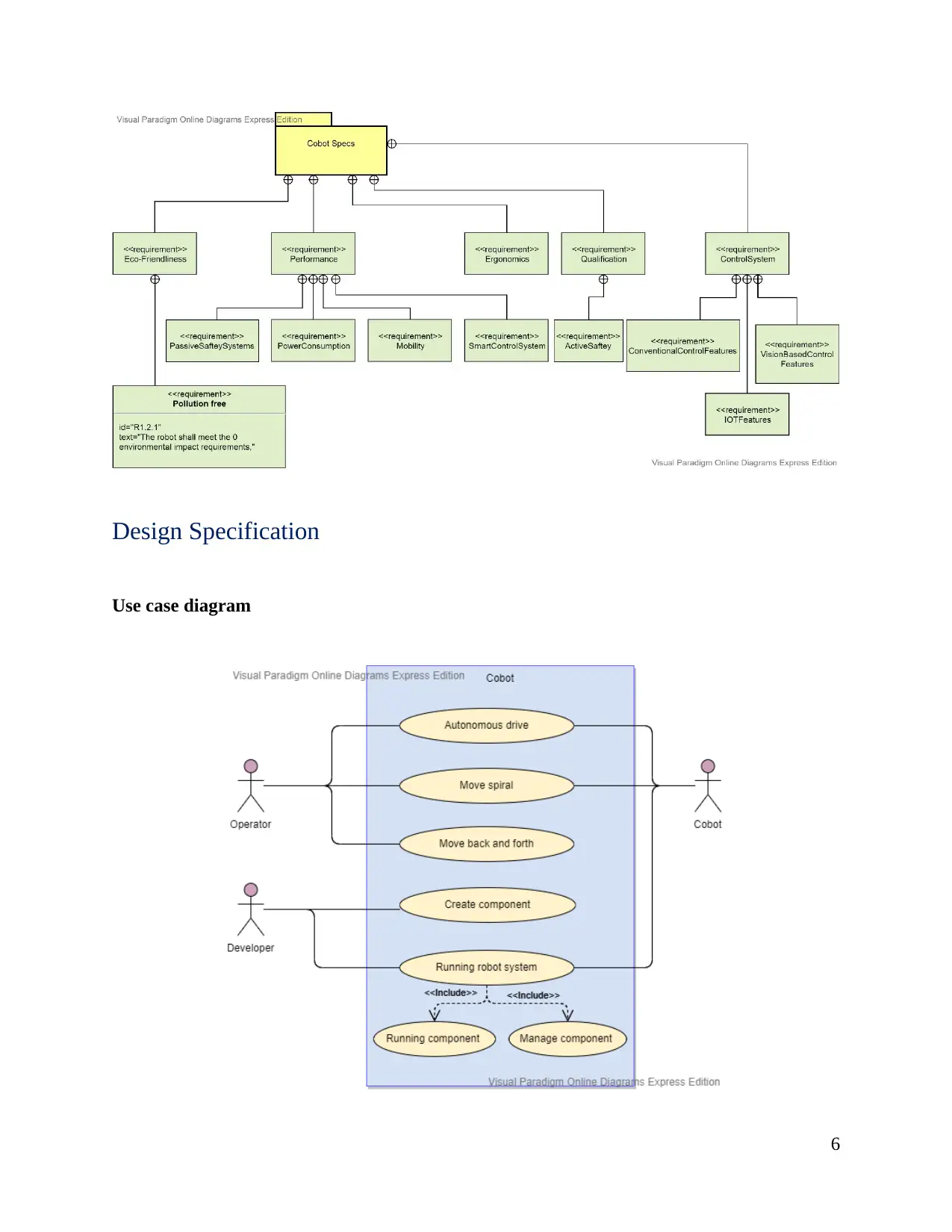
Design Specification
Use case diagram
6
Use case diagram
6
Paraphrase This Document
Need a fresh take? Get an instant paraphrase of this document with our AI Paraphraser
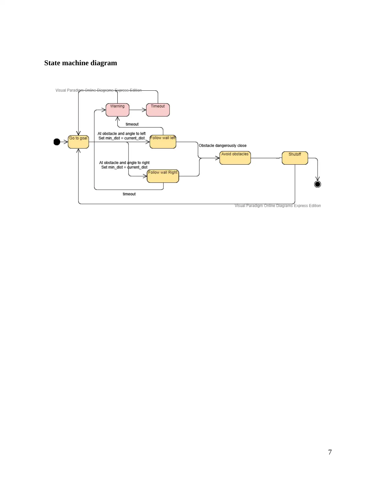
State machine diagram
7
7
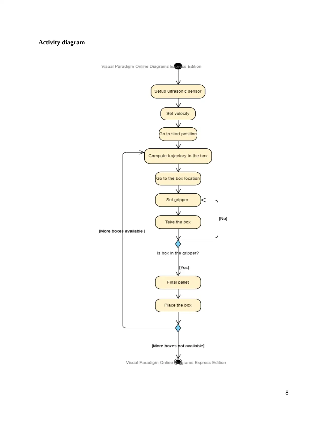
Activity diagram
8
8
⊘ This is a preview!⊘
Do you want full access?
Subscribe today to unlock all pages.
Trusted by 1+ million students worldwide
In the diagram, A* algorithm has been utilized by the action “compute trajectory to the
box” for receiving an already defined environment’s map along with all the fixed obstacles on it.
The programming of the action is undertaken in 2 stages on the DaNI robot: 1st: the robot
moving to the position of box, 2nd: the robot moving to final pallet. Once the robot comes to the
box position after performing 1st stage, the gripper will be configured and positioned to take the
box under the action “set gripper ready” whose programming was done on the NXT Lego. The
trajectory’s 2nd stage followed by the robot moving to the “go to final pallet” action is
performed once the indication regarding the gripper taking the box is given by the sensors. The
robot finds out the gripper which is followed up leaving the box on the pallet properly. After this,
the robot returns to the starting position and the process is repeated again for other boxes. The
sonar sensor finds the dynamic obstacles during which the robot stops, however, the path is
continued on no detection of obstacles.
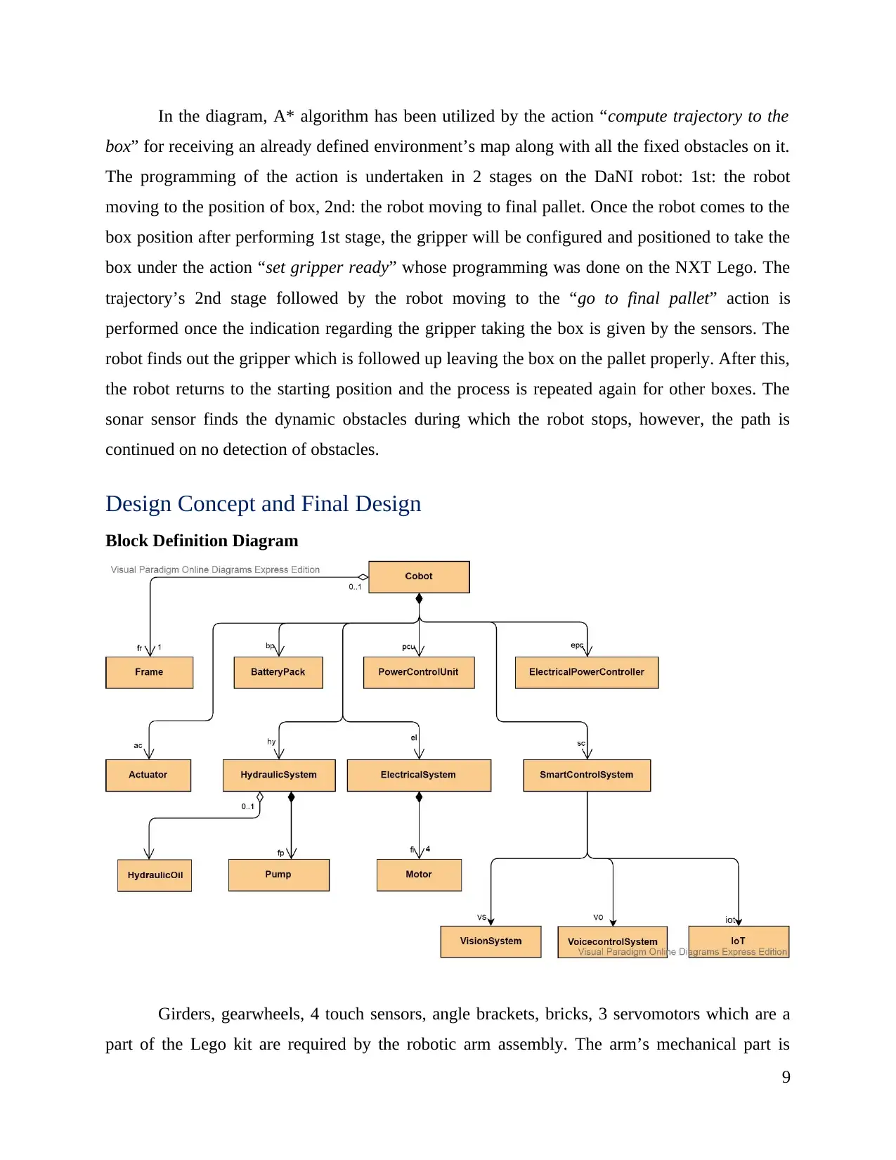
Design Concept and Final Design
Block Definition Diagram
Girders, gearwheels, 4 touch sensors, angle brackets, bricks, 3 servomotors which are a
part of the Lego kit are required by the robotic arm assembly. The arm’s mechanical part is
9
box” for receiving an already defined environment’s map along with all the fixed obstacles on it.
The programming of the action is undertaken in 2 stages on the DaNI robot: 1st: the robot
moving to the position of box, 2nd: the robot moving to final pallet. Once the robot comes to the
box position after performing 1st stage, the gripper will be configured and positioned to take the
box under the action “set gripper ready” whose programming was done on the NXT Lego. The
trajectory’s 2nd stage followed by the robot moving to the “go to final pallet” action is
performed once the indication regarding the gripper taking the box is given by the sensors. The
robot finds out the gripper which is followed up leaving the box on the pallet properly. After this,
the robot returns to the starting position and the process is repeated again for other boxes. The
sonar sensor finds the dynamic obstacles during which the robot stops, however, the path is
continued on no detection of obstacles.
Design Concept and Final Design
Block Definition Diagram
Girders, gearwheels, 4 touch sensors, angle brackets, bricks, 3 servomotors which are a
part of the Lego kit are required by the robotic arm assembly. The arm’s mechanical part is
9
Paraphrase This Document
Need a fresh take? Get an instant paraphrase of this document with our AI Paraphraser
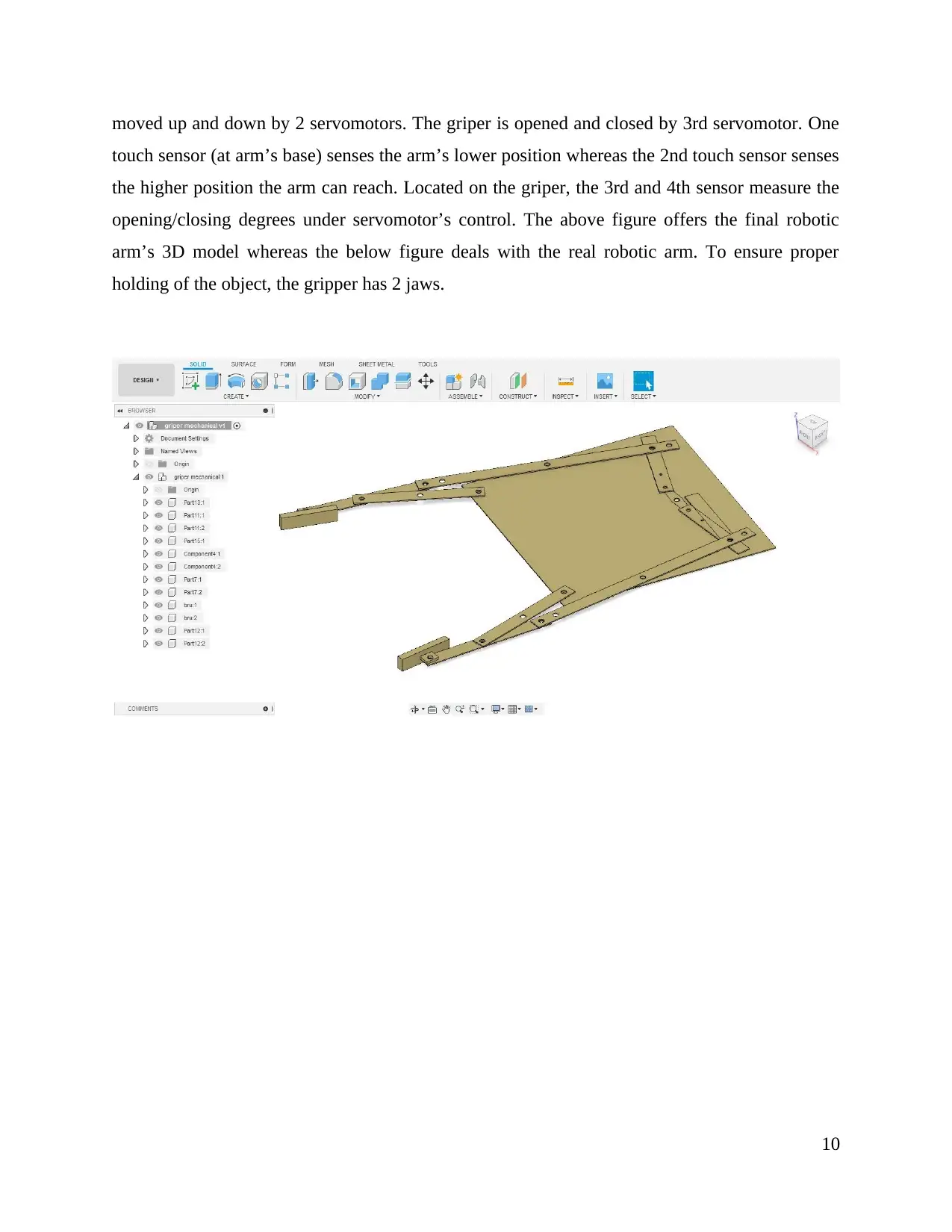
moved up and down by 2 servomotors. The griper is opened and closed by 3rd servomotor. One
touch sensor (at arm’s base) senses the arm’s lower position whereas the 2nd touch sensor senses
the higher position the arm can reach. Located on the griper, the 3rd and 4th sensor measure the
opening/closing degrees under servomotor’s control. The above figure offers the final robotic
arm’s 3D model whereas the below figure deals with the real robotic arm. To ensure proper
holding of the object, the gripper has 2 jaws.
10
Results and Analysis
Obstacle detection
The developers can resort to the below mentioned 4 phrase strategy for the purpose of
overcoming these issues:
Pre-processing- After collecting the data from sensors and cameras, the data gets
converted to a highly beneficial form. In this case, for the purpose of voice command
identification and record mikes, IoT sensors as well as 3 cameras were utilized.
Detection of Feature- The pre-processed data is used to fetch the important features like
edges, corners and others.
Detection and classification of Object: The features are used for object identification
which is followed up by classification based on known feature maps.
Tracking & navigation of object- The identified objects are exposed to time tracking. As
the robot tends to navigate, this may be inclusive of both the objects as well as dynamic
environment viewpoints.
Servos can be controlled; decisions can be taken and other top-level robot-based tasks
can be undertaken based on the generated data.
Real world data is collected by the robot with the help of multiple cameras and sensors.
However, for meeting the set goals exact predictions and measurements are needed, for which
this data may prove to be raw. So, in order to clean the data to make it more beneficial, Digital
Signal Processing might be resorted to. For instance, resizing, contrast enhancement and gamma
correction can be used in case of cleaning the image data.
Proper planning as to how much and how quick the image data is to be collected is a
must. Since 2 stereo images can be supported by the robot, so it’s crucial for the system to
undertake 2 planes process simultaneously. Numerous resolution configurations in the range of
16-32 megapixels as well as frame rates (In 30-60fps range) are also supported. Also, high &
low-speed connectors can be utilized for collection of varied frequency and bit rates related
11
⊘ This is a preview!⊘
Do you want full access?
Subscribe today to unlock all pages.
Trusted by 1+ million students worldwide
1 out of 23
Related Documents


Your All-in-One AI-Powered Toolkit for Academic Success.
+13062052269
info@desklib.com
Available 24*7 on WhatsApp / Email
![[object Object]](/_next/static/media/star-bottom.7253800d.svg)
Unlock your academic potential
Copyright © 2020–2026 A2Z Services. All Rights Reserved. Developed and managed by ZUCOL.