Design and Implementation of a Smart Collaborative Robot with AI
VerifiedAdded on 2022/08/26
|28
|5623
|22
Report
AI Summary
This report details the Model Based System Engineering of a smart collaborative robot designed for packaging applications. The project encompasses the development of an autonomous packing robot, incorporating vision, voice, and IIoT capabilities. The report begins with an introduction to the background and scope, followed by the aim and objectives of the project. A state-of-the-art review provides context for the design, and the methodology section outlines the use of Model-Based Systems Engineering (MBSE) and SysML for system modeling. The requirements specification defines the functional and performance requirements of the robot, including payload, vision system, IoT integration, actuating system, and control system. The design specification further elaborates on these aspects, justifying the design choices. The report includes SysML diagrams such as requirement, use case, block definition, parametric, activity, and state machine diagrams to illustrate the system's architecture and behavior. Python simulations and CAD models are also developed to validate the design. The results and discussion section analyzes the performance of the robot. The report concludes with a summary of the project's achievements and potential future improvements. References are provided to support the findings.
Model Based System Engineering of a smart collaborative robot with vision, voice and IIoT capabilities
Paraphrase This Document
Need a fresh take? Get an instant paraphrase of this document with our AI Paraphraser
2
Table of Contents
1. Introduction..............................................................................................................................2
1.1 Background.......................................................................................................................2
1.2 Scope.................................................................................................................................3
2. Aim and Objectives..................................................................................................................4
3. State of the Art.........................................................................................................................5
4. Methodology............................................................................................................................8
5. Requirements Specification....................................................................................................10
6. Design Specification...............................................................................................................11
7. Design concepts and the final design.....................................................................................13
8. System Modelling using SysML............................................................................................14
8.1 Requirement Diagram.....................................................................................................14
8.2 Use Case Diagram...........................................................................................................15
8.3 Block Definition Diagram/Internal Block Diagram........................................................16
8.4 Parametric Diagram........................................................................................................16
8.5 Activity Diagram/Sequence Diagram.............................................................................17
8.6 State Machine diagram describing the control logic.......................................................18
9. Simulations & CAD Models..................................................................................................19
9.1 Python Simulation and Results.......................................................................................19
9.2 CAD Models...................................................................................................................21
10. Results & Discussion..........................................................................................................22
11. Conclusion..........................................................................................................................23
References......................................................................................................................................24
2
1. Introduction
1.1 Background
It is getting a bit difficult to spot the difference between the collaborative robot tasks and the
industrial robot tasks, and the dominance of collaborative robots in the market is getting clearer
as these robots may be taking over a great market share by leaving behind the industrial robots.
Usually, industrial robots are kept aside for safety purposes and are only called in when the
tough manufacturing tasks like welding are in hand. While the collaborative robots are safe
enough to keep up with the humans and helping in the tasks where no industrial strength is
required. But the things are changing in the industry as the process of implementation of
collaborative robots in any size of the facility is getting easier because these robots are getting
smarter as well as tougher.
Being getting smarter and tougher, collaborative robots could be handling industrial tasks soon.
As the intelligence of collaborative robots leads to more productivity with flexibility, the
manufacturers might desire these robots even more to get maximum return on investment (ROI).
All these trends remind us that collaborative robots will start entering the industrial sector soon
enough.
1.2 Scope
The packaging process in the industry is a really crucial process. The easily integrated and highly
reliable robot automation makes this process easy. Specifically designed robots will take care of
the processes like loading and unloading of boxes, mixing, feeding, and the wrapping. The
design and optimization will be done for the packaging process with the payload of up to 30 kg.
Even the packaging applications like race tracking packing and tracking of moving conveyors
will be done through controllers, software, vision technology, and these robots. The main
highlight is that this automated process must be capable of working with humans as they will be
checking each component and placing it on the conveyors.
⊘ This is a preview!⊘
Do you want full access?
Subscribe today to unlock all pages.
Trusted by 1+ million students worldwide
2
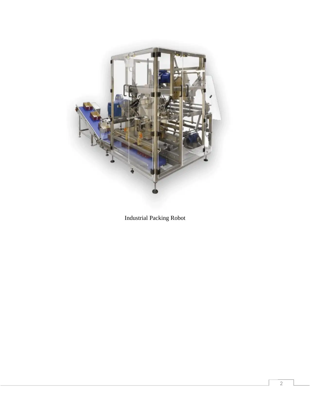
Industrial Packing Robot
Industrial Packing Robot
Paraphrase This Document
Need a fresh take? Get an instant paraphrase of this document with our AI Paraphraser
2
2. Aim and Objectives
The main aim of this project work is to develop the autonomous packing robot. That must
capable of performing packing, wrapping, and palletizing etc. The robot will be implemented in
the footwear manufacturing company. Also, the robot must capable of working with humans and
synchronous conveyors.
Performing initial analysis
Collecting relevant literature
Carry out System modelling process
Finalizing the robot design
Finding scope for improvement
2
3. State of the Art
The packaging process of irregular definitely has issues and the engineering and science
researchers have started to focus on these issues lately. However, there have some constraints
when it comes to the tasks being more manageable and the demands of a given application.
The discussion among the researchers has the main topic of heuristic nesting algorithm for
irregular parts. [8] Trim loss is also being affected by some factors which are also part of the
discussion. The theme of the application shows that the process involves rectangular stock sheets
and the cutting procedure is done to get bill-of-materials. The author likes to take on the problem
through a systematic approach that results well. Performance measurements are developed based
on the produced results. The authors also go through the already published work in this specific
area and find out that there were techniques that were developed for the packaging process of the
irregular shapes but weren’t published due to commercial confidentiality. The irregular shapes in
these studies were presented as non-overlapping rectangles. As a matter of fact, the authors
clearly mention that no more than five non-overlapping orthogonal rectangles can represent each
and every part in their study. [21] The orientation of each part in the system is like that (a) its
length is greater than its height and (b) in the upper-right corner there is the largest
complimentary (void) area. The sorting of the parts is done on the basis of non-increasing part
height. The packing of shapes is done in a raster fashion and the layers are build up
demonstrating intermeshed packed shapes. There are two disadvantages to this approach. The
first disadvantage is the use of rectangles for the approximation of the packing of shapes. [18]
The second disadvantage is assuming that orthogonal will be good patterns for packing.
Instead of using the rectangle, the author chooses polygons to examine the nesting of shapes. The
authors keep in mind the minimizing waste while discussing the favourable way of packing of
two-dimensional polygons [1]. The nesting of congruent2 convex figures is the one where the
algorithm can be applied. [13] The problem here is referred to as the ‘template-layout problem’
in which a number of irregulars yet similar pieces are cut from a steel board. To make it more
convenient, the authors create two sub-problems out of this one problem. In the first sub-
problem, the most appropriate convex polygon is used for the favourable (minimal waste)
⊘ This is a preview!⊘
Do you want full access?
Subscribe today to unlock all pages.
Trusted by 1+ million students worldwide
2
circumscription of the original irregular shape [7]. The circumscription of the convex polygon in
the other sub-problem is done another polygon that can pave the plane that is, covering it with
the replication of the same figures with no gaps or overlaps. It is referred to as the paver polygon.
There are limitations to this approach as it can only be applied to congruent convex figures and
the waste in the margin is neglected because of the assumption that the packing plane is
infinite[19]. Other limitations include the only possible application of this approach to convex
components with straight sides. The paving techniques are used for the nesting of both regular
and irregular identical components.
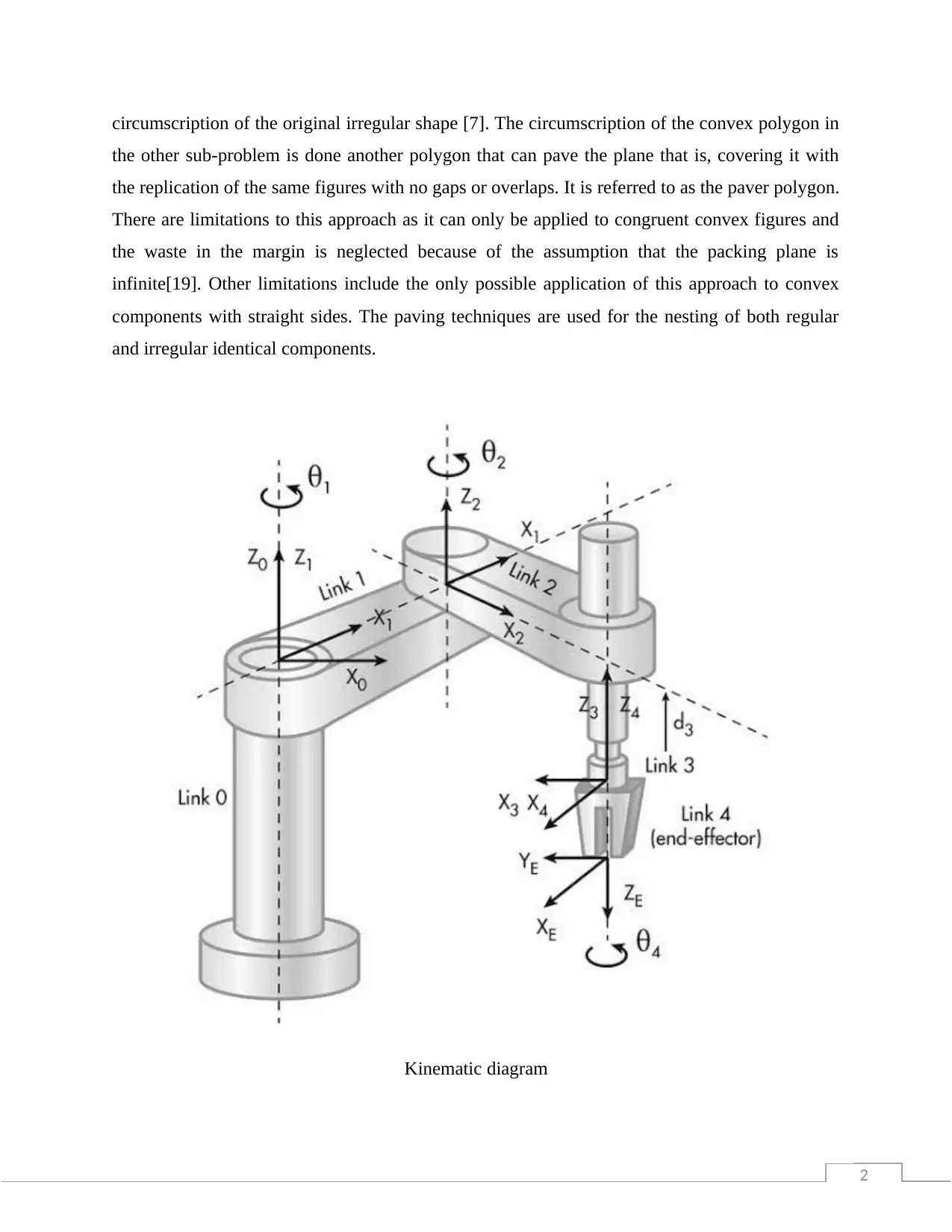
Kinematic diagram
circumscription of the original irregular shape [7]. The circumscription of the convex polygon in
the other sub-problem is done another polygon that can pave the plane that is, covering it with
the replication of the same figures with no gaps or overlaps. It is referred to as the paver polygon.
There are limitations to this approach as it can only be applied to congruent convex figures and
the waste in the margin is neglected because of the assumption that the packing plane is
infinite[19]. Other limitations include the only possible application of this approach to convex
components with straight sides. The paving techniques are used for the nesting of both regular
and irregular identical components.
Kinematic diagram
Paraphrase This Document
Need a fresh take? Get an instant paraphrase of this document with our AI Paraphraser
2
The author developed a system to determine how to cut two-dimensional, regular or irregular,
pieces from shaped (regular or irregular) materials and this system is an automated testing
system. There are some constraints that must be considered for this process. [9] One constraint is
that there are defective regions in the material, an animal hide, which is to be cut. For example,
this problem also appears in industries like the shoe industry and leather upholstery [26]. In
pursuit of determining an efficient nesting position, an object-orientated representational
arrangement in combination with a heuristic search procedure is implemented in this approach.
The authors focus on settling for a satisfactory solution instead of shattering all the possible
packing positions while going after a favourable solution. A solution is seen as a satisfactory
solution if it yields better or equal results compared to the average results of the solution from a
human expert. The evaluation of the overall system is done by doing its performance comparison
against a human expert, and within a 5% average yield difference is claimed. [31]
2
4. Methodology
A multi-disciplinary engineering model in which models are used to support design,
specifications, analysis, and verification of the developed system instead of using documents, is
known as Model-Based Systems Engineering (MBSE). The purpose of creating a Model-Based
Systems Engineering (MBSE) is to establish a digital model of a system so that all the
engineering disciplines, as well as the functional group in the company, can use it easily.
Another use of the MBSE model is carrying out the simulation of the system’s performance in
the same way as Model-Based Development. The flowcharts represented by the MBSE model
are created with System Modeling Language (SysML). Diverse information is presented in the
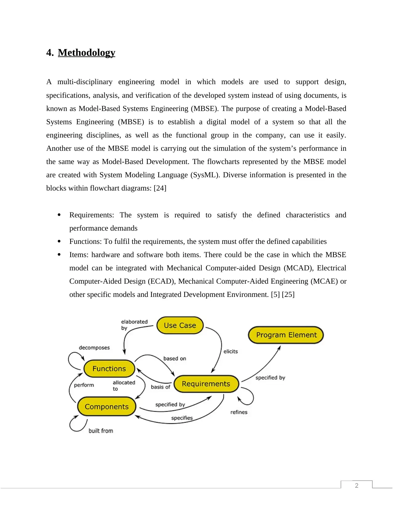
blocks within flowchart diagrams: [24]
Requirements: The system is required to satisfy the defined characteristics and
performance demands
Functions: To fulfil the requirements, the system must offer the defined capabilities
Items: hardware and software both items. There could be the case in which the MBSE
model can be integrated with Mechanical Computer-aided Design (MCAD), Electrical
Computer-Aided Design (ECAD), Mechanical Computer-Aided Engineering (MCAE) or
other specific models and Integrated Development Environment. [5] [25]
4. Methodology
A multi-disciplinary engineering model in which models are used to support design,
specifications, analysis, and verification of the developed system instead of using documents, is
known as Model-Based Systems Engineering (MBSE). The purpose of creating a Model-Based
Systems Engineering (MBSE) is to establish a digital model of a system so that all the
engineering disciplines, as well as the functional group in the company, can use it easily.
Another use of the MBSE model is carrying out the simulation of the system’s performance in
the same way as Model-Based Development. The flowcharts represented by the MBSE model
are created with System Modeling Language (SysML). Diverse information is presented in the
blocks within flowchart diagrams: [24]
Requirements: The system is required to satisfy the defined characteristics and
performance demands
Functions: To fulfil the requirements, the system must offer the defined capabilities
Items: hardware and software both items. There could be the case in which the MBSE
model can be integrated with Mechanical Computer-aided Design (MCAD), Electrical
Computer-Aided Design (ECAD), Mechanical Computer-Aided Engineering (MCAE) or
other specific models and Integrated Development Environment. [5] [25]
⊘ This is a preview!⊘
Do you want full access?
Subscribe today to unlock all pages.
Trusted by 1+ million students worldwide
2
Justification of the selected approach
Clear Communications between Engineering Disciplines: Usually, the systems use multiple
spreadsheets, presentations, and documents. Misinterpretations among the defined documents are
the main issue which might bring errors and delay the development process. [22] A single
definition could solve the problems like this as all the confusion and ambiguity will be over.
Traceability of Change: Engineers get on with different trade studies during the development
process to assess the alternative and find the different possible designs. When it comes to the
MBSE model, everything is defined clearly so the engineers can easily determine what will be
the effects of a change. For instance, an engineer can see the items related to functions that are
further related to requirements. [29] An engineer can also see the alternative of these relations.
This helps in clearing the impact which is done due to the change in design.
Paraphrase This Document
Need a fresh take? Get an instant paraphrase of this document with our AI Paraphraser
2
5. Requirements Specification
The packaging process is crucial and the easy integration of the robot automation process
increases the flexibility and reliability of the packing process. The specifically designed robots
will take care of all the processes like loading and unloading of boxes, mixing of the elements,
feeding of the products, and film wrapping of the final products. This packing process with the
robots will be designed and optimized for a payload of up to 30 kg. Along with the race track,
packing and tracking of the moving conveyors, these robots, controllers, vision technology, and
the software will be a great help in all kinds of packing processes. [27] The crucial point is that
all of it has to be capable enough to work with humans. Human labour is responsible for
checking and putting back each and every part back on the conveyor after examining.
All the problems which are associated with the automated packing and nesting of irregular
shapes are of great importance. There are great industrial interested associated with these
problems as well. Robotics, Adaptive material handling systems, and automated assembly are
important because the ability of these to manipulate objects along with visual control is the key
task out of many others. It is of great importance that the capability of these systems must be
trustworthy enough for handling variable products in different procedures in the industrial
environment. It is essential that these systems will have to be able to handle and manipulate
arbitrary shapes in a flexible way. [15] Several techniques like machine vision and flexible
packing strategies must be combined together to create automated material handling systems that
are essential to automate this part of the manufacturing process.
2
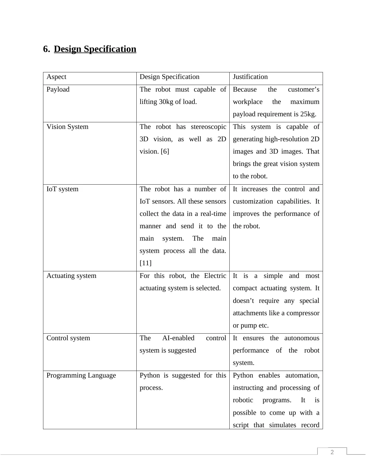
6. Design Specification
Aspect Design Specification Justification
Payload The robot must capable of
lifting 30kg of load.
Because the customer’s
workplace the maximum
payload requirement is 25kg.
Vision System The robot has stereoscopic
3D vision, as well as 2D
vision. [6]
This system is capable of
generating high-resolution 2D
images and 3D images. That
brings the great vision system
to the robot.
IoT system The robot has a number of
IoT sensors. All these sensors
collect the data in a real-time
manner and send it to the
main system. The main
system process all the data.
[11]
It increases the control and
customization capabilities. It
improves the performance of
the robot.
Actuating system For this robot, the Electric
actuating system is selected.
It is a simple and most
compact actuating system. It
doesn’t require any special
attachments like a compressor
or pump etc.
Control system The AI-enabled control
system is suggested
It ensures the autonomous
performance of the robot
system.
Programming Language Python is suggested for this
process.
Python enables automation,
instructing and processing of
robotic programs. It is
possible to come up with a
script that simulates record
⊘ This is a preview!⊘
Do you want full access?
Subscribe today to unlock all pages.
Trusted by 1+ million students worldwide
1 out of 28


Your All-in-One AI-Powered Toolkit for Academic Success.
+13062052269
info@desklib.com
Available 24*7 on WhatsApp / Email
![[object Object]](/_next/static/media/star-bottom.7253800d.svg)
Unlock your academic potential
Copyright © 2020–2026 A2Z Services. All Rights Reserved. Developed and managed by ZUCOL.