MSc Building Services: Electrical Services Design Assignment

Verified

Added on  2023/06/15

|18
|2360
|463
Practical Assignment
AI Summary
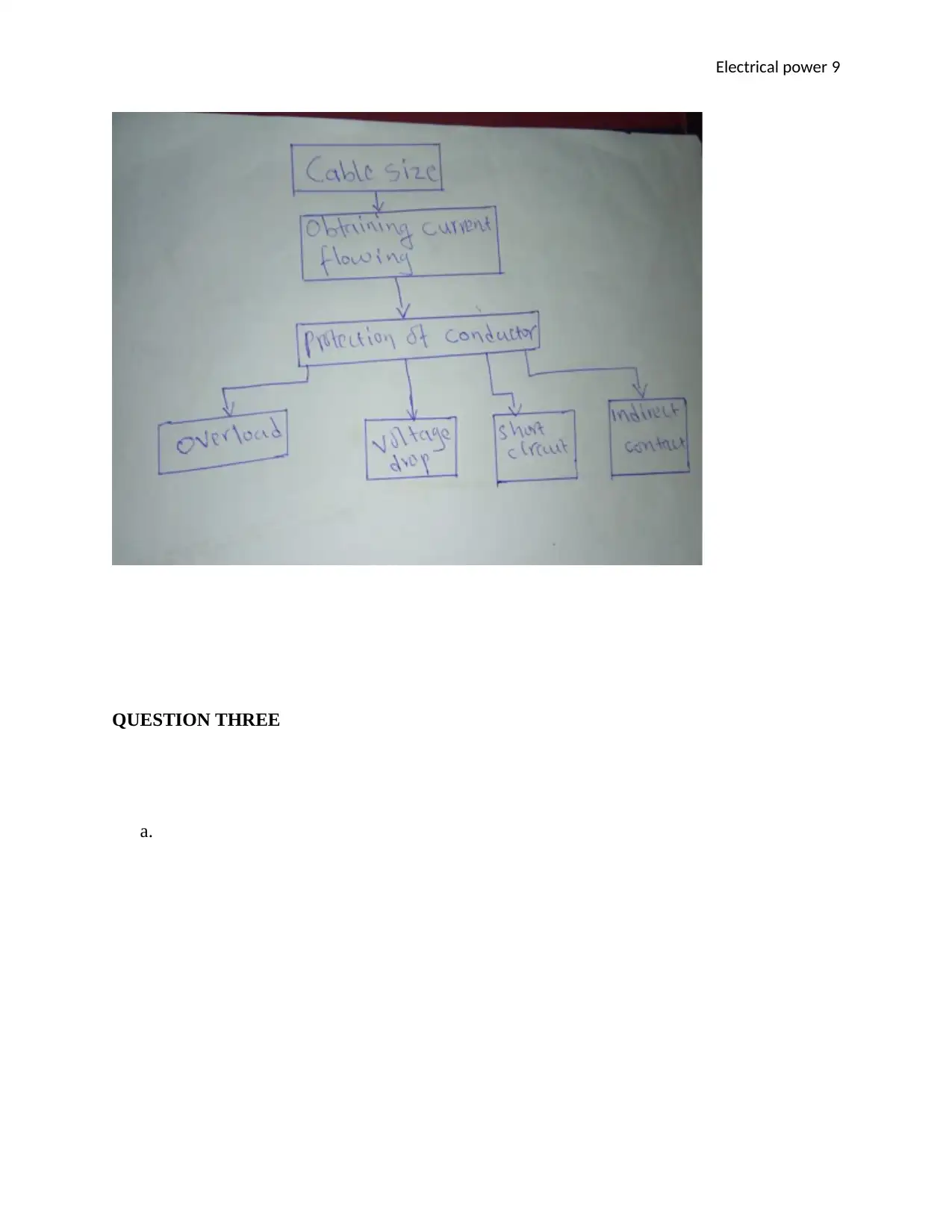
This assignment solution details the electrical services design for a 5-story commercial building, addressing key aspects such as cable sizing based on BS 7671, overload protection, short circuit protection, indirect contact, and voltage drop. It includes calculations for cable size selection, considering factors like insulation type, voltage drop, and current carrying capacity. The document also covers discrimination in protective devices, the impact of ambient temperature on conductor sizing, and methods for mitigating harmonics in electrical systems. Furthermore, it provides a voltage drop calculation for a busbar system and discusses the installation of a standby generator, ensuring compliance with electrical characteristics and derating factors. The solution uses flow diagrams and equations to illustrate the design process and assumptions made during calculations. This resource is available on Desklib, which offers a range of study tools and solved assignments for students.
Document Page
Electrical power 1
ELECTRICAL POWER
By Name
Course
Instructor
Institution
Location
Date
tabler-icon-diamond-filled.svg

Paraphrase This Document

Need a fresh take? Get an instant paraphrase of this document with our AI Paraphraser
Document Page
Electrical power 2
QUESTION ONE
a. Categories of A and B of MCCB ( Molded Case Circuit Breaker)
Category A
Without an international short time delay for choosiness for conditions of short circuit and
hence without a short circuit withstanding rating of current. For this category, they are actually
miniature circuit breaker which operates at the end of the socket outlets and the final distribution.
If a short circuit occurs, they will trip immediately (Bird, 2012).
Category B
This category of MCCB has withstood breaking ability. Hence they do not essentially trip in
case of any short circuit. This will make the downstream circuit breakers to switch off.
b.
We always impose an upper limit on the earth fault loop impedance to ensure that all the faults
are covered within that range (Hambley, 2017). With the upper limit most electrical appliances
if not all are fully protected by the earth loop impedance protection. There is a different circuit
with different loads and rating (socket outlets and lighting circuits’ protections are different). In
cases where we cannot attain the upper limit, we employ the correct cable sizes calculations to
ensure that a suitable and a perfect cable size is employed.
c.
Document Page
Electrical power 3
Discrimination is an act of choosing a protective device and adjusting their settings in order to
limit interruption to electrical installations under fault conditions (Hesse, 2011). This can be
checked through evaluation of current and time discrimination.
Time discrimination: This is checked as the circuit breaker are put to withstand electrodynamics
effects and thermal effects of the current fault at the time of the delay (delay period).
Current discrimination: This has two kinds of discrimination (overload discrimination and
short circuit discrimination). The overload is checked through a selection of an upstream device
having a higher current rating and a pickup level for the next downstream device. While the
short circuit is checked through setting a circuit breaker to a limit which doesn’t cause
unnecessary trip (Ojwach, 2012).
d. Ambient temperature has a direct impact on the conductor sizing. The temperature to be
considered is that of the air around the cables used during the installation. Depending on
the ambient temperature set, the size of insulation will be chosen for a particular ambient
temperature. For our case, the ambient temperature is 400 and 300 for the rest of the rest
of the building. The PVC insulation which will be required is 0.77 mm all-round the
cable.
Grouping of circuits together will lead to a reduction current carry capacity and this is suitable
for correction factors hence it will ensure that there is no overheating in the cables (PRASAD,
2014).
Document Page
Electrical power 4
e.
Overheating occurs in a conductor when the current through the passing through the conductor is
too high for the size of the cable, therefore, the correct size of the cable is obtained through
calculation. Choosing the accurate cable during installation is vital to ensure an acceptable
conductors’ life and insulation subjected to the thermal effects of carrying current for long
periods of time in ordinary service (Smith, 2013).
And the calculation of the cable size is done using the below equation.
S = (Ia² …………………………………………………………
tabler-icon-diamond-filled.svg

Paraphrase This Document

Need a fresh take? Get an instant paraphrase of this document with our AI Paraphraser
Document Page
Electrical power 5
t) ……………………1
k
whe
re
S is the minimum protective conductor cross-sectional area
(mm2)
Ia is the fault current (A)
t is the opening time of the protective device (s)
k is a factor depending on the conductor material and
insulation, and the initial and maximum insulation
temperatures (Tharaja, 2013).
QUESTION TWO
Option A
Draw a flow diagram to show how you would select a cable size that satisfies the BS 7671
protection requirements for Overload, Short Circuit, Indirect Contact and Voltage Drop
Protection against overload
For the selection of the conductor size in order to avoid overheating the following are taken into
account;
The type of the insulation which will define the maximum permissible temperature during the
operation, and according to CIBSE the insulation of EPR can withstand 900 C while the PVC can
withstand 700 C (Tonardo, 2013). Therefore from the formula of getting the overload thermal as
Document Page
Electrical power 6
V=I2R . . . . . . . . . . . . . . . . . . . . . . . . . . . . . . . . . . . . . . . . . . . . . . . . . . . . . . . . . . . . . . . . . . . . . . 2
So when a given voltage is pushing a current then the resistance can be obtained, lets assume that
the resistance is 0.2 Ω
R= A
L . . . . . . . . . . . . . . . . . . . . . . . . . . . . . . . . . . . . . . . . . . . . . . . . . . . . . . . . . . . . . . . . . . . . . . .
3
And taking the conductor to be copper = 1.72 × 10 -8
The length can be taken as 100 m
0.2= 1.72×1 08 A
100
A= 1176470588 m2
A=π r2
r= 1.9 mm
Cable size according to the voltage drop.
The cable size can be selected from the voltage drop, and this is done through some calculations
(John, 2013).
Assuming that
Current rating= 250 A/ ampere
Document Page
Electrical power 7
R1= 0.5 m Ω/ft
X1= 0. 4m Ω/ft
The total length =72ft
Power factor = 0.9
The voltage drop
V= 3I (R1cos ɵ + X1sin ɵ)
Where V is the voltage drop in volts, I is the current in ampere/ phase, R1 is the conductive
resistance in ohm/ft, X1 is conductor inductive in ohm/ft, ɵ is the angle obtained from power
factor and L is one way length of the circuit source to load in kft (Couling, 2015).
Power factor = cos ɵ
ɵ= cos-1 0.9
ɵ = 25.840.
L= 72
1000
L= 0.072 kft
V= 3I (R1cos ɵ + X1sin ɵ)
V= 1.73× 250 [ (0.5 × cos 25.84) + ( 0.4 × sin 25.84 )] × 0.072
tabler-icon-diamond-filled.svg

Paraphrase This Document

Need a fresh take? Get an instant paraphrase of this document with our AI Paraphraser
Document Page
Electrical power 8
V= 433× 0.6243× 0.072
V = 19.46 volts
Voltage drop 6 %
The size of the cable is obtained by the following equation
r= VD ×1000
3× L× I
r= 0.06× 1000
1.732× 0.072× 250
r= 60
31.176
r= 1.92 mm
D= 3.89 mm
Document Page
Electrical power 9
QUESTION THREE
a.
Document Page
Electrical power 10
tabler-icon-diamond-filled.svg

Paraphrase This Document

Need a fresh take? Get an instant paraphrase of this document with our AI Paraphraser
Document Page
Electrical power 11
b.
The ground floor distribution is connected 2 meters while the other five floors have 4 meters
each.
Current rating= 250 A/ ampere
R1= 0.38 m Ω/m
X1= 0.13m Ω/m
Document Page
Electrical power 12
The total length is given by 2+ (4×5) = 22 m
The voltage drop along the length of Busbar 2 (East) can be given by the following equations
V= 3I (R1cos ɵ + X1sin ɵ) . . . . . . . . . . . . . . . . . . . . . . . . . . . . . . . . . . . . . . . . . . . . . . . . . . . . 2
Where V is the voltage drop in volts, I is the current in ampere/ phase, R1 is the conductive
resistance in ohm/ft, X1 is conductor inductive in ohm/ft, ɵ is the angle obtained from power
factor and L is one way length of the circuit source to load in kft (Katz, 2010).
Power factor = cos ɵ
ɵ= cos-1 0.9
ɵ = 25.840.
And from 1 ft= 0.3048m
R1= 0.38 ×0.3048
R1= 0.115824Ω/ft
X1= 0.13 ×0.3048
X1= 0.0396 Ω/ft
L= 22 m
L= 22/0.3048
chevron_up_icon
1 out of 18
circle_padding
hide_on_mobile
zoom_out_icon
[object Object]