Report on Designing a Multi-Stage Bi-Polar Amplifier in Electronics

Verified

Added on  2023/04/11

|3
|313
|182
Report
AI Summary
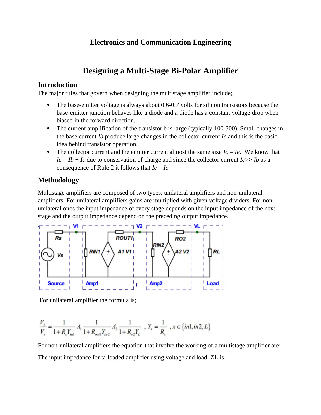
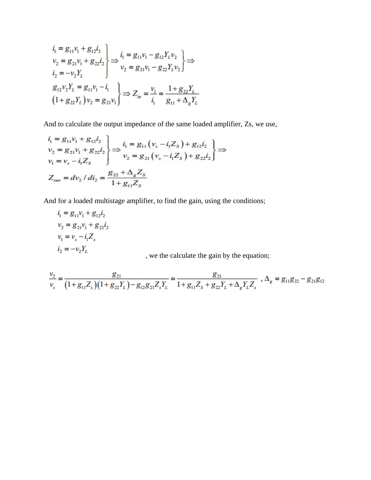
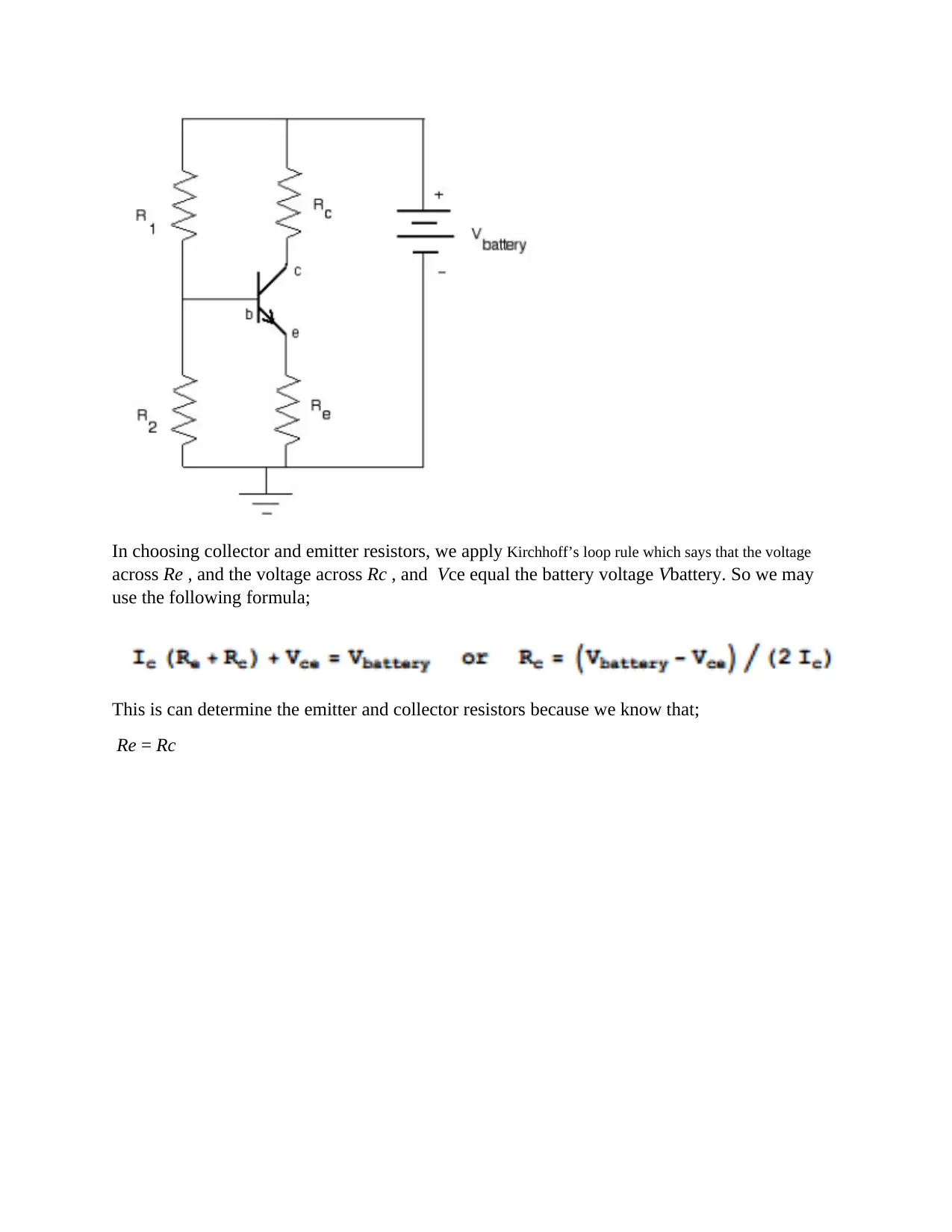
This report provides a detailed solution for designing a multi-stage bi-polar amplifier in Electronics and Communication Engineering. It outlines the fundamental rules governing amplifier design, including the behavior of base-emitter voltage, transistor current amplification, and the relationship between collector and emitter currents. The methodology section differentiates between unilateral and non-unilateral amplifiers, presenting the relevant formulas for calculating input impedance, output impedance, and gain. It also explains the application of Kirchhoff’s loop rule for selecting appropriate collector and emitter resistors, ensuring proper voltage distribution within the amplifier circuit. This document is designed to help students understand the complexities involved in designing multi-stage bi-polar amplifiers.
Document Page
Electronics and Communication Engineering
Designing a Multi-Stage Bi-Polar Amplifier
Introduction
The major rules that govern when designing the multistage amplifier include;
The base-emitter voltage is always about 0.6-0.7 volts for silicon transistors because the
base-emitter junction behaves like a diode and a diode has a constant voltage drop when
biased in the forward direction.
The current amplification of the transistor b is large (typically 100-300). Small changes in
the base current Ib produce large changes in the collector current Ic and this is the basic
idea behind transistor operation.
The collector current and the emitter current almost the same size Ic = Ie. We know that
Ie = Ib + Ic due to conservation of charge and since the collector current Ic>> Ib as a
consequence of Rule 2 it follows that Ic = Ie
Methodology
Multistage amplifiers are composed of two types; unilateral amplifiers and non-unilateral
amplifiers. For unilateral amplifiers gains are multiplied with given voltage dividers. For non-
unilateral ones the input impedance of every stage depends on the input impedance of the next
stage and the output impedance depend on the preceding output impedance.
For unilateral amplifier the formula is;
For non-unilateral amplifiers the equation that involve the working of a multistage amplifier are;
The input impedance for ta loaded amplifier using voltage and load, ZL is,
tabler-icon-diamond-filled.svg

Paraphrase This Document

Need a fresh take? Get an instant paraphrase of this document with our AI Paraphraser
Document Page
And to calculate the output impedance of the same loaded amplifier, Zs, we use,
And for a loaded multistage amplifier, to find the gain, using the conditions;
, we the calculate the gain by the equation;
Document Page
In choosing collector and emitter resistors, we apply Kirchhoff’s loop rule which says that the voltage
across Re , and the voltage across Rc , and Vce equal the battery voltage Vbattery. So we may
use the following formula;
This is can determine the emitter and collector resistors because we know that;
Re = Rc
chevron_up_icon
1 out of 3
circle_padding
hide_on_mobile
zoom_out_icon
[object Object]