Principles of Naval Architecture: Ship Design & System Integration
VerifiedAdded on 2023/04/08
|27
|6177
|206
Report
AI Summary
This report provides a comprehensive overview of ship design and system integration within the fields of naval architecture and marine engineering. It explores the multifaceted, iterative nature of ship design, influenced by client vision, cost efficiency, and regulatory compliance. Key areas covered include engineering drawing, ship structure and construction, hydrostatics, ship stability, resistance, propulsion, sea keeping, maneuvering, marine machinery and system design, and air conditioning. The report further examines design factors such as commercial aspects, operational requirements, and external regulations, emphasizing the importance of collaboration between designers, clients, and suppliers. It also delves into system integration, propeller and engine selection, fuel consumption estimation, and mechanical and thermodynamics related to main and auxiliary engineering systems. The document concludes by highlighting the critical role of advanced software and close cooperation in achieving successful ship designs for the future.
PRINCIPLES OF NAVAL ARCHITECTURE AND MARINE ENGINEERING
SHIP DESIGN AND SYSTEM INTEGRATION
Flor S. Lagat
BEng Naval Architecture and Marine Engineering
University of Southampton
SHIP DESIGN AND SYSTEM INTEGRATION
Flor S. Lagat
BEng Naval Architecture and Marine Engineering
University of Southampton
Paraphrase This Document
Need a fresh take? Get an instant paraphrase of this document with our AI Paraphraser
SHIP DESIGN AND SYSTEM INTEGRATION
Abstract
Ship design is a complex, iterative and various procedure, influenced by some factors.
Based on the vision of a customer, the ship designer must develop the most cost-efficient
ship for a designated task, in a period of boundaries of international and national rules and
regulations. Studying the best compromise within the given boundaries is the challenge for
the ship architect and system integrator. In the offshore sector, merchant vessel design is
getting more and more diverse, with more stringent rules and regulations ensuring safe and
secure operation, as well as more advanced operational requirements.
Furthermore, the physical and functional integration of systems and equipment on board is
getting more complex. 2D and 3D design, modelling, simulation, and calculation software are
playing an important part in making the design process more efficient and successful. A
successfully designed ship is the result of close and good cooperation between the designer,
the customer, the yard and the equipment suppliers. None of these players can be left out in
the process of designing the ships of the future.
TABLE OF CONTENTS
Abstract.......................................................................................................................................
Research background..................................................................................................................
Literature review..........................................................................................................................
Engineering Drawing and Ship Design.........................................................................................
Ship Structure and Construction..................................................................................................
Hydrostatics.................................................................................................................................
Ship Stability................................................................................................................................
Ship resistance............................................................................................................................
Ship Propulsion............................................................................................................................
See keeping and Maneuvering....................................................................................................
Marine Machinery & System Design............................................................................................
Marine Engines & Air Conditioning..............................................................................................
Ship Design-Design factors and requirements.............................................................................
Commercial Aspects....................................................................................................................
Operational Requirements.........................................................................................................
External requirements................................................................................................................
Ship Design – The Design Process............................................................................................
Engineering Drawing/Computer Aided Design (CAD) Drawing..................................................
System Integration.....................................................................................................................
The propeller and engine selecting system................................................................................
Fuel consumption estimation.....................................................................................................
Specific fuel oil consumption......................................................................................................
The main propulsion shaft torque and speed measurement......................................................
Engine effective power...............................................................................................................
Mechanical and thermodynamics relating to the main and auxiliary engineering
systems..........................................................................................................................
Thermal efficiency......................................................................................................................
Conclusion.................................................................................................................................
References................................................................................................................................
⊘ This is a preview!⊘
Do you want full access?
Subscribe today to unlock all pages.
Trusted by 1+ million students worldwide
Research background
In the Historical perspective, the design of ships has been based on the nature of the
existing vessel designs and on the minor breakthrough innovations, which have helped the
industry to make some of the positive steps. Currently, the design of ships has been
developed whereby the ships are customized to meet the expectations of the clients, needs
of the market and new regulations regarding ship design and construction (Zubaly, 2018).
The modern design and construction can be categorized into two categories, i.e., the design
of ships which evolve from the research and development project of the ship designers or
the design of ships from a sustained development together with the client. The research and
development projects in most cases are independent of the contract projects and are usually
based on the long-term strategies (Lewis, 2016).
The ship designers start an innovative process, based on market studies and new ideas and
concepts. After a successful design process, the new ship design will be introduced to the
market. This report will focus on developing a broad understanding of Naval Architecture and
Marine Engineering fields such as ship design, construction, hydrostatics, ship stability,
resistance, propulsion, structural design, sea keeping, manoeuvring.
Paraphrase This Document
Need a fresh take? Get an instant paraphrase of this document with our AI Paraphraser
Literature review
Engineering Drawing and Ship Design
Engineering drawing refers to technical drawings which are used to clearly and fully define
the requirements for an engineering item. The engineering activities are used to produce
engineering drawings. The drawings are more than the mere drawing of the pictures; it is
also the language which is used. The language used in the engineering drawing is a
graphical language which is used to communicate ideas and information from one part to
another (Tuppe, 2014). The professional who is involved in the design of ships are referred
to as naval architects, and the architecture of designing ship is referred to as naval
architecture. The naval architects are responsible for the design, survey, classification,
construction, and maintenance of boats, ships and other naval vessels and other offshore
structures.
Ship Structure and Construction
Ship structure refers to a box girder which is composed of stiffened plates such as deck
plating, side shells platting and the bottom plating, while ship construction refers to the
building of ships and other floating vessels which includes ships and boats. The construction
of these vessels takes place in a specialized facility referred to as a shipyard. The personnel
involved in the construction of ships are referred to as shipbuilders are known as
shipwrights, the science of ship construction and maintenance, both for military and
commercial purposes is referred to as naval engineering (Collins, 2011).
Hydrostatics
Hydrostatics in naval engineering refers to the branch of physics which deals with the
characteristics of fluids which are at rest and in most cases in with the pressure in
water or any other fluid or the pressure exerted by a fluid on the immersed body (Lewis,
Principles of Naval Architecture: Motions in waves and controllability, 2018).
Ship Stability
To understand the idea behind the stability of a floating ship one needs to understand the
concept of equilibrium. Regarding ship stability, the total of three types of equilibrium
conditions which can develop to a floating ship, rely upon on the connection between the
situations of centre of gravity and the centre of buoyancy.
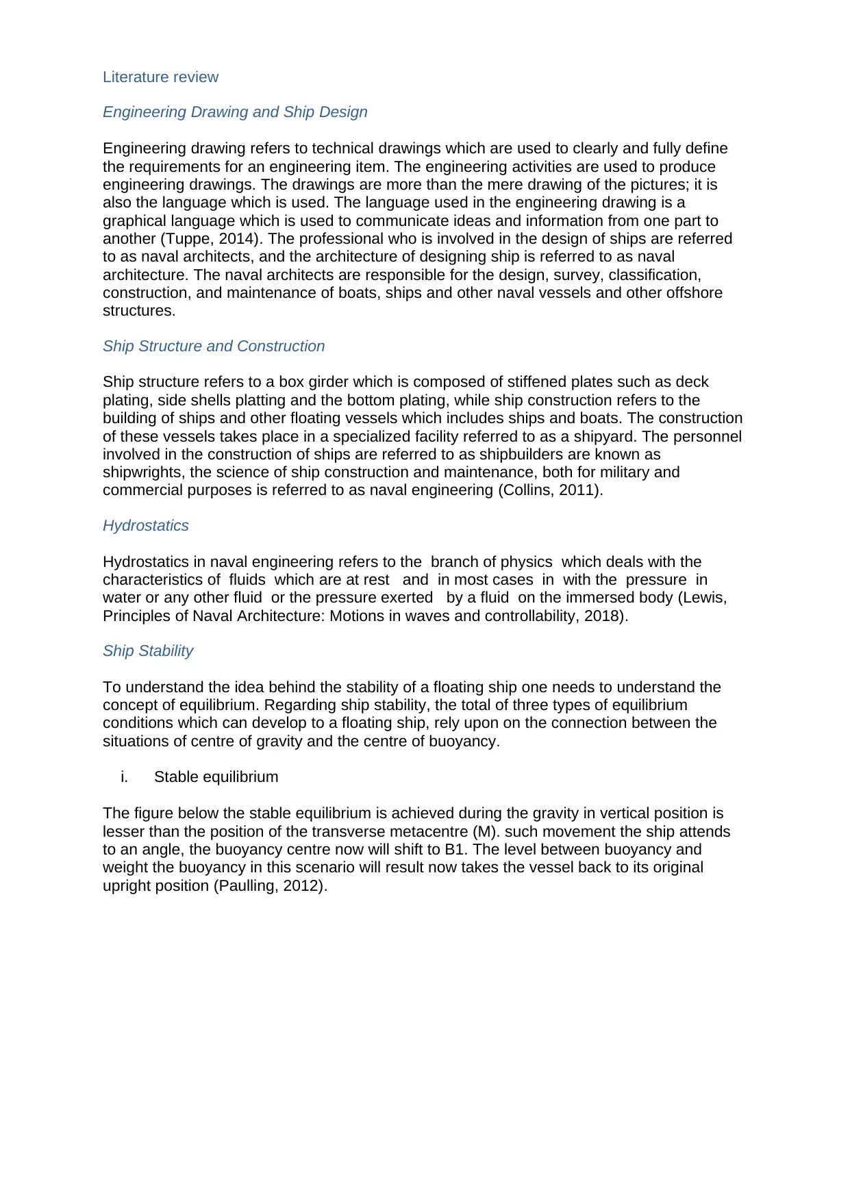
i. Stable equilibrium
The figure below the stable equilibrium is achieved during the gravity in vertical position is
lesser than the position of the transverse metacentre (M). such movement the ship attends
to an angle, the buoyancy centre now will shift to B1. The level between buoyancy and
weight the buoyancy in this scenario will result now takes the vessel back to its original
upright position (Paulling, 2012).
Engineering Drawing and Ship Design
Engineering drawing refers to technical drawings which are used to clearly and fully define
the requirements for an engineering item. The engineering activities are used to produce
engineering drawings. The drawings are more than the mere drawing of the pictures; it is
also the language which is used. The language used in the engineering drawing is a
graphical language which is used to communicate ideas and information from one part to
another (Tuppe, 2014). The professional who is involved in the design of ships are referred
to as naval architects, and the architecture of designing ship is referred to as naval
architecture. The naval architects are responsible for the design, survey, classification,
construction, and maintenance of boats, ships and other naval vessels and other offshore
structures.
Ship Structure and Construction
Ship structure refers to a box girder which is composed of stiffened plates such as deck
plating, side shells platting and the bottom plating, while ship construction refers to the
building of ships and other floating vessels which includes ships and boats. The construction
of these vessels takes place in a specialized facility referred to as a shipyard. The personnel
involved in the construction of ships are referred to as shipbuilders are known as
shipwrights, the science of ship construction and maintenance, both for military and
commercial purposes is referred to as naval engineering (Collins, 2011).
Hydrostatics
Hydrostatics in naval engineering refers to the branch of physics which deals with the
characteristics of fluids which are at rest and in most cases in with the pressure in
water or any other fluid or the pressure exerted by a fluid on the immersed body (Lewis,
Principles of Naval Architecture: Motions in waves and controllability, 2018).
Ship Stability
To understand the idea behind the stability of a floating ship one needs to understand the
concept of equilibrium. Regarding ship stability, the total of three types of equilibrium
conditions which can develop to a floating ship, rely upon on the connection between the
situations of centre of gravity and the centre of buoyancy.
i. Stable equilibrium
The figure below the stable equilibrium is achieved during the gravity in vertical position is
lesser than the position of the transverse metacentre (M). such movement the ship attends
to an angle, the buoyancy centre now will shift to B1. The level between buoyancy and
weight the buoyancy in this scenario will result now takes the vessel back to its original
upright position (Paulling, 2012).
The moment causing up the righting of the ship into initial positioning is called Righting
Moment. The righting of a ship is the segregation of vertical lines transient across the B1 and
G. Then abbreviated is named as GZ.
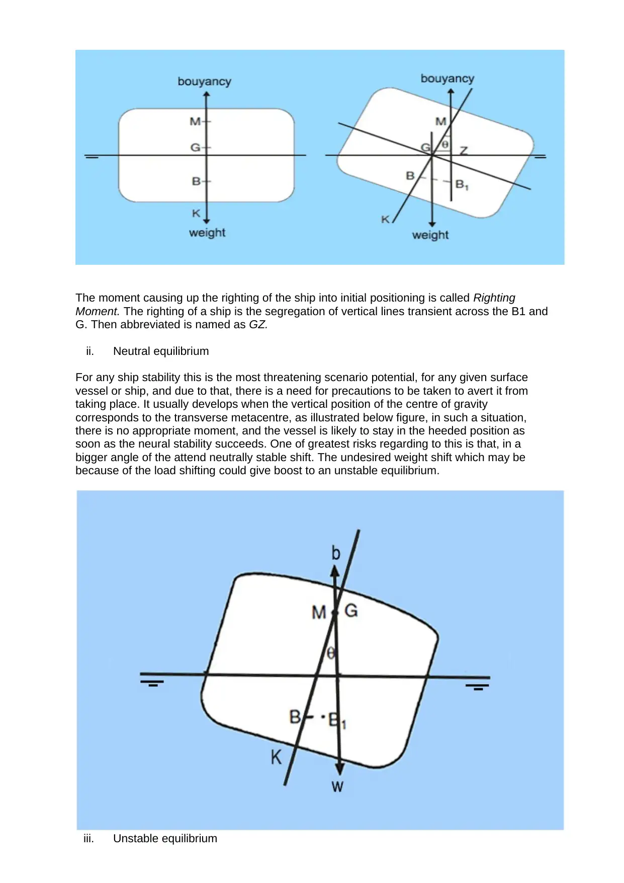
ii. Neutral equilibrium
For any ship stability this is the most threatening scenario potential, for any given surface
vessel or ship, and due to that, there is a need for precautions to be taken to avert it from
taking place. It usually develops when the vertical position of the centre of gravity
corresponds to the transverse metacentre, as illustrated below figure, in such a situation,
there is no appropriate moment, and the vessel is likely to stay in the heeded position as
soon as the neural stability succeeds. One of greatest risks regarding to this is that, in a
bigger angle of the attend neutrally stable shift. The undesired weight shift which may be
because of the load shifting could give boost to an unstable equilibrium.
iii. Unstable equilibrium
Moment. The righting of a ship is the segregation of vertical lines transient across the B1 and
G. Then abbreviated is named as GZ.
ii. Neutral equilibrium
For any ship stability this is the most threatening scenario potential, for any given surface
vessel or ship, and due to that, there is a need for precautions to be taken to avert it from
taking place. It usually develops when the vertical position of the centre of gravity
corresponds to the transverse metacentre, as illustrated below figure, in such a situation,
there is no appropriate moment, and the vessel is likely to stay in the heeded position as
soon as the neural stability succeeds. One of greatest risks regarding to this is that, in a
bigger angle of the attend neutrally stable shift. The undesired weight shift which may be
because of the load shifting could give boost to an unstable equilibrium.
iii. Unstable equilibrium
⊘ This is a preview!⊘
Do you want full access?
Subscribe today to unlock all pages.
Trusted by 1+ million students worldwide
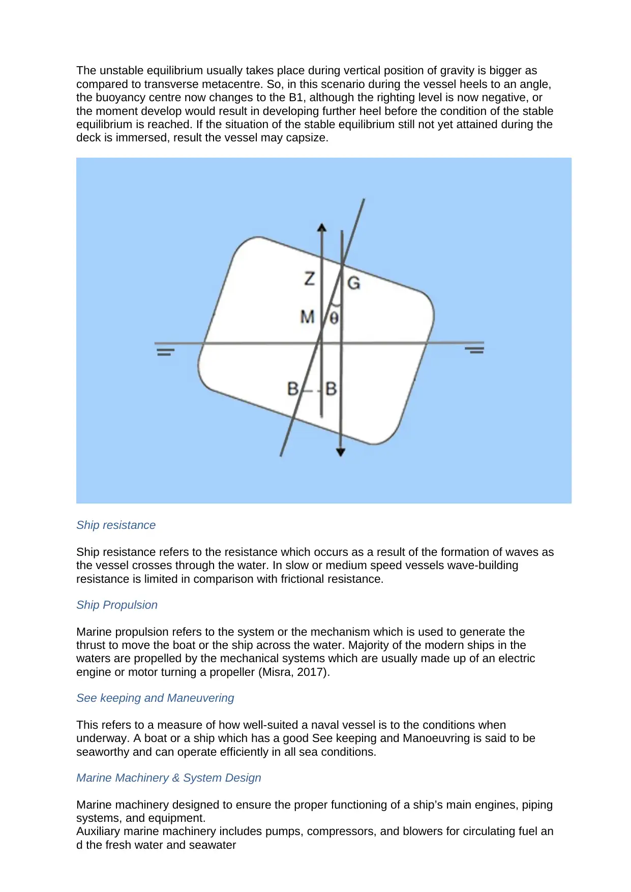
The unstable equilibrium usually takes place during vertical position of gravity is bigger as
compared to transverse metacentre. So, in this scenario during the vessel heels to an angle,
the buoyancy centre now changes to the B1, although the righting level is now negative, or
the moment develop would result in developing further heel before the condition of the stable
equilibrium is reached. If the situation of the stable equilibrium still not yet attained during the
deck is immersed, result the vessel may capsize.
Ship resistance
Ship resistance refers to the resistance which occurs as a result of the formation of waves as
the vessel crosses through the water. In slow or medium speed vessels wave-building
resistance is limited in comparison with frictional resistance.
Ship Propulsion
Marine propulsion refers to the system or the mechanism which is used to generate the
thrust to move the boat or the ship across the water. Majority of the modern ships in the
waters are propelled by the mechanical systems which are usually made up of an electric
engine or motor turning a propeller (Misra, 2017).
See keeping and Maneuvering
This refers to a measure of how well-suited a naval vessel is to the conditions when
underway. A boat or a ship which has a good See keeping and Manoeuvring is said to be
seaworthy and can operate efficiently in all sea conditions.
Marine Machinery & System Design
Marine machinery designed to ensure the proper functioning of a ship’s main engines, piping
systems, and equipment.
Auxiliary marine machinery includes pumps, compressors, and blowers for circulating fuel an
d the fresh water and seawater
Paraphrase This Document
Need a fresh take? Get an instant paraphrase of this document with our AI Paraphraser
used in cooling systems, for supplying air to the starting system of the main engine, for cooli
ng refrigerated holds, and for air-conditioning various parts of the ship and for refrigeration m
achinery (Lewis, Principles of Naval Architecture: Resistance, propulsion and vibration,
2013).
Marine Engines & Air Conditioning
Air conditioning refers to the treatment of air in the ship or any other naval vessel aimed at
modifying the internal environment in terms of fresh air, humidity and temperature. In the
ship air conditioning system, it usually rejects the heat from the space to be cooled into the
surrounding seawater through flow in seawater cooled condenser (Mansour, 2015).
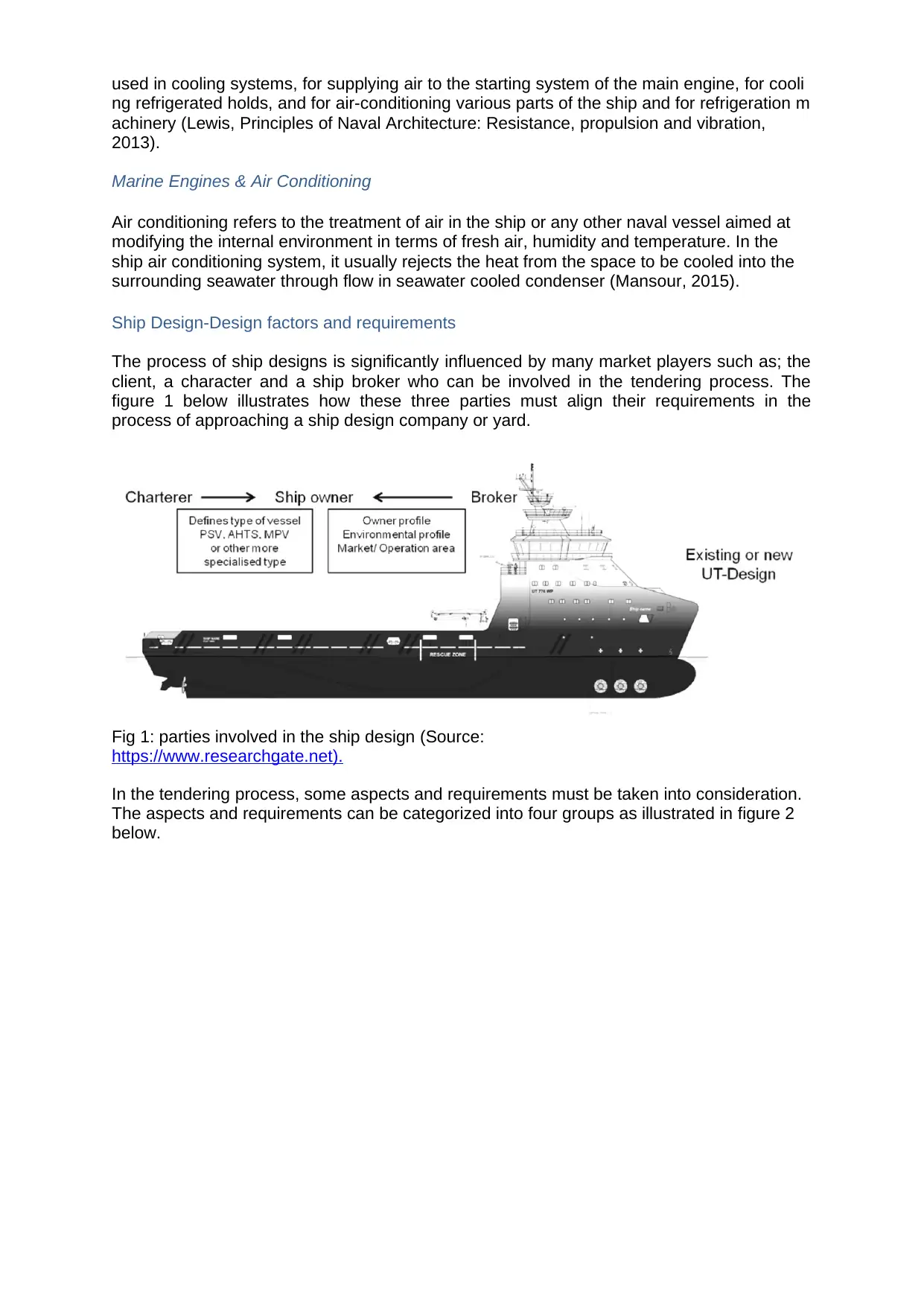
Ship Design-Design factors and requirements
The process of ship designs is significantly influenced by many market players such as; the
client, a character and a ship broker who can be involved in the tendering process. The
figure 1 below illustrates how these three parties must align their requirements in the
process of approaching a ship design company or yard.
Fig 1: parties involved in the ship design (Source:
https://www.researchgate.net).
In the tendering process, some aspects and requirements must be taken into consideration.
The aspects and requirements can be categorized into four groups as illustrated in figure 2
below.
ng refrigerated holds, and for air-conditioning various parts of the ship and for refrigeration m
achinery (Lewis, Principles of Naval Architecture: Resistance, propulsion and vibration,
2013).
Marine Engines & Air Conditioning
Air conditioning refers to the treatment of air in the ship or any other naval vessel aimed at
modifying the internal environment in terms of fresh air, humidity and temperature. In the
ship air conditioning system, it usually rejects the heat from the space to be cooled into the
surrounding seawater through flow in seawater cooled condenser (Mansour, 2015).
Ship Design-Design factors and requirements
The process of ship designs is significantly influenced by many market players such as; the
client, a character and a ship broker who can be involved in the tendering process. The
figure 1 below illustrates how these three parties must align their requirements in the
process of approaching a ship design company or yard.
Fig 1: parties involved in the ship design (Source:
https://www.researchgate.net).
In the tendering process, some aspects and requirements must be taken into consideration.
The aspects and requirements can be categorized into four groups as illustrated in figure 2
below.
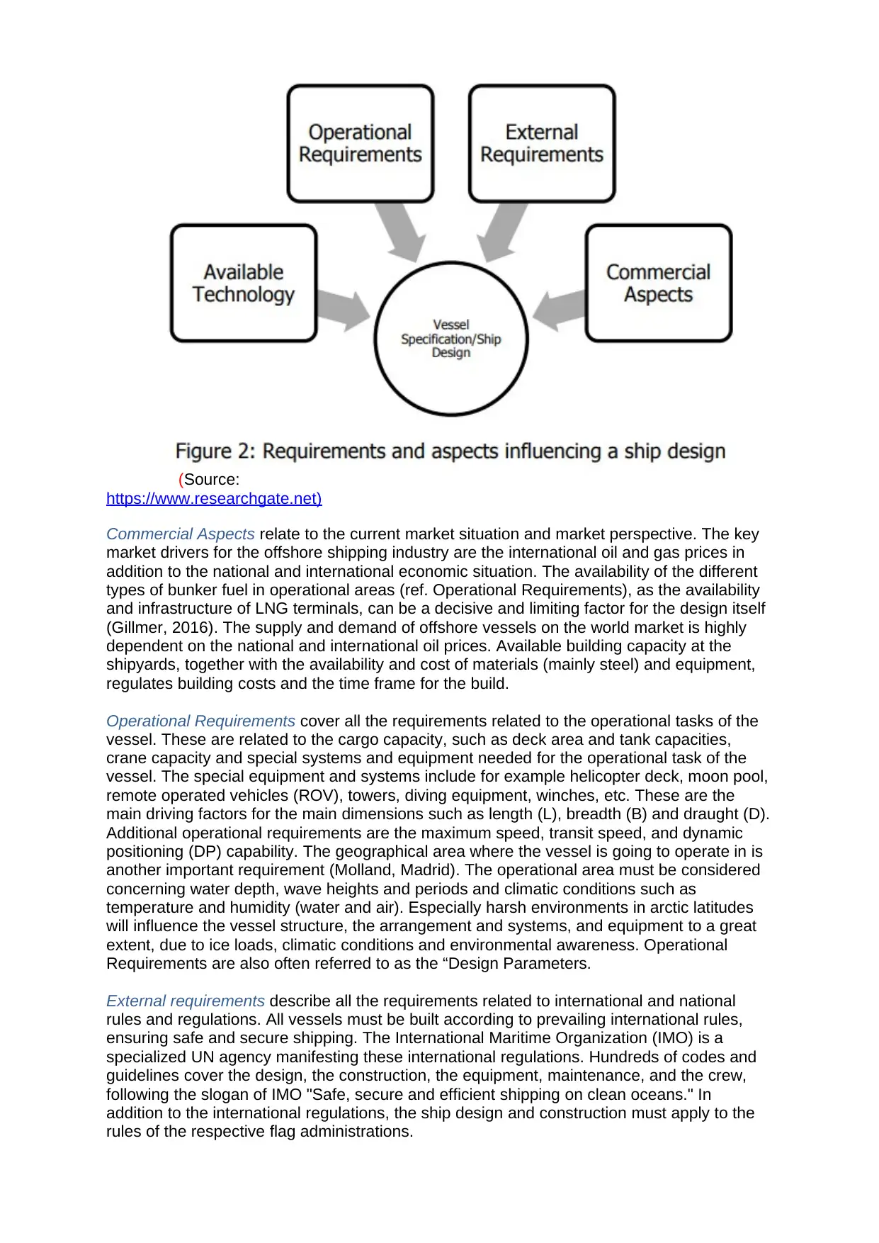
(Source:
https://www.researchgate.net)
Commercial Aspects relate to the current market situation and market perspective. The key
market drivers for the offshore shipping industry are the international oil and gas prices in
addition to the national and international economic situation. The availability of the different
types of bunker fuel in operational areas (ref. Operational Requirements), as the availability
and infrastructure of LNG terminals, can be a decisive and limiting factor for the design itself
(Gillmer, 2016). The supply and demand of offshore vessels on the world market is highly
dependent on the national and international oil prices. Available building capacity at the
shipyards, together with the availability and cost of materials (mainly steel) and equipment,
regulates building costs and the time frame for the build.
Operational Requirements cover all the requirements related to the operational tasks of the
vessel. These are related to the cargo capacity, such as deck area and tank capacities,
crane capacity and special systems and equipment needed for the operational task of the
vessel. The special equipment and systems include for example helicopter deck, moon pool,
remote operated vehicles (ROV), towers, diving equipment, winches, etc. These are the
main driving factors for the main dimensions such as length (L), breadth (B) and draught (D).
Additional operational requirements are the maximum speed, transit speed, and dynamic
positioning (DP) capability. The geographical area where the vessel is going to operate in is
another important requirement (Molland, Madrid). The operational area must be considered
concerning water depth, wave heights and periods and climatic conditions such as
temperature and humidity (water and air). Especially harsh environments in arctic latitudes
will influence the vessel structure, the arrangement and systems, and equipment to a great
extent, due to ice loads, climatic conditions and environmental awareness. Operational
Requirements are also often referred to as the “Design Parameters.
External requirements describe all the requirements related to international and national
rules and regulations. All vessels must be built according to prevailing international rules,
ensuring safe and secure shipping. The International Maritime Organization (IMO) is a
specialized UN agency manifesting these international regulations. Hundreds of codes and
guidelines cover the design, the construction, the equipment, maintenance, and the crew,
following the slogan of IMO "Safe, secure and efficient shipping on clean oceans." In
addition to the international regulations, the ship design and construction must apply to the
rules of the respective flag administrations.
⊘ This is a preview!⊘
Do you want full access?
Subscribe today to unlock all pages.
Trusted by 1+ million students worldwide
On top of that, certain specific restrictions might apply due to the operational area of the ship
(see for example MARPOL Annex VI: Prevention of air pollution by ships). Emission Control
Areas (ECA) limit emissions to air, introducing solutions such as gas-fuelled engines,
exhaust gas cleaning and low sulphur fuels. A classification society, listed accordingly to
IMO and authorized by the flag administration, is an independent organization verifying the
compliance with its own classification rules during construction and the service life of a
vessel (Stokoe, 2010).
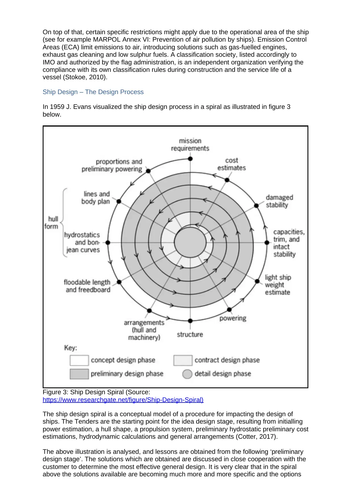
Ship Design – The Design Process
In 1959 J. Evans visualized the ship design process in a spiral as illustrated in figure 3
below.
Figure 3: Ship Design Spiral (Source:
https://www.researchgate.net/figure/Ship-Design-Spiral)
The ship design spiral is a conceptual model of a procedure for impacting the design of
ships. The Tenders are the starting point for the idea design stage, resulting from initialling
power estimation, a hull shape, a propulsion system, preliminary hydrostatic preliminary cost
estimations, hydrodynamic calculations and general arrangements (Cotter, 2017).
The above illustration is analysed, and lessons are obtained from the following ‘preliminary
design stage’. The solutions which are obtained are discussed in close cooperation with the
customer to determine the most effective general design. It is very clear that in the spiral
above the solutions available are becoming much more and more specific and the options
(see for example MARPOL Annex VI: Prevention of air pollution by ships). Emission Control
Areas (ECA) limit emissions to air, introducing solutions such as gas-fuelled engines,
exhaust gas cleaning and low sulphur fuels. A classification society, listed accordingly to
IMO and authorized by the flag administration, is an independent organization verifying the
compliance with its own classification rules during construction and the service life of a
vessel (Stokoe, 2010).
Ship Design – The Design Process
In 1959 J. Evans visualized the ship design process in a spiral as illustrated in figure 3
below.
Figure 3: Ship Design Spiral (Source:
https://www.researchgate.net/figure/Ship-Design-Spiral)
The ship design spiral is a conceptual model of a procedure for impacting the design of
ships. The Tenders are the starting point for the idea design stage, resulting from initialling
power estimation, a hull shape, a propulsion system, preliminary hydrostatic preliminary cost
estimations, hydrodynamic calculations and general arrangements (Cotter, 2017).
The above illustration is analysed, and lessons are obtained from the following ‘preliminary
design stage’. The solutions which are obtained are discussed in close cooperation with the
customer to determine the most effective general design. It is very clear that in the spiral
above the solutions available are becoming much more and more specific and the options
Paraphrase This Document
Need a fresh take? Get an instant paraphrase of this document with our AI Paraphraser
available are narrowed down. In a successful tender process, a final proposal and a contract
proposal lead to a signed design contract, and the detailed design and real building process
begin (Personnel, 2010).
In the ship designing process, many tools and equipment are used. This includes and not
limited to CFD calculations, simulations, 3D modelling, and tank tests. In the recent past, the
application and availability of the simulation and calculation software have increased; this
has been attributed to the fact that the computer utility is today cheaper and requires less
processing time. The results obtained from the simulations and calculations help the
designers to verify predictions and at the same time to optimize the design (Biran, 2015).
The updated tools such as the soft wares help speed up iterations of the design spiral.
However, the tasks remain unchanged since the design spiral was drawn in 1959. Besides
verifying assumptions and predictions in the design process by calculations, computer-based
modelling, and tank tests, it is important to incorporate the feedback and experience of the
customers/users. This feedback is essential to constantly improve vessel designs and to
stay ahead of the competition. Really important feedback in this context is the logging of the
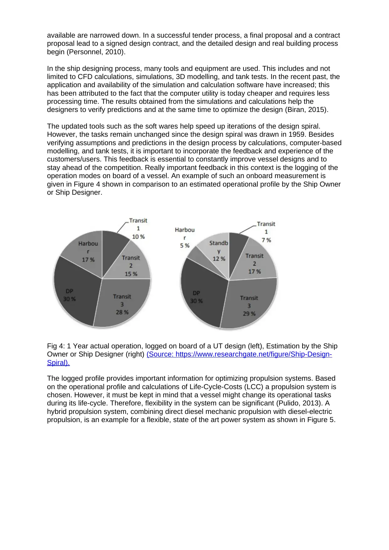
operation modes on board of a vessel. An example of such an onboard measurement is
given in Figure 4 shown in comparison to an estimated operational profile by the Ship Owner
or Ship Designer.
Fig 4: 1 Year actual operation, logged on board of a UT design (left), Estimation by the Ship
Owner or Ship Designer (right) (Source: https://www.researchgate.net/figure/Ship-Design-
Spiral).
The logged profile provides important information for optimizing propulsion systems. Based
on the operational profile and calculations of Life-Cycle-Costs (LCC) a propulsion system is
chosen. However, it must be kept in mind that a vessel might change its operational tasks
during its life-cycle. Therefore, flexibility in the system can be significant (Pulido, 2013). A
hybrid propulsion system, combining direct diesel mechanic propulsion with diesel-electric
propulsion, is an example for a flexible, state of the art power system as shown in Figure 5.
proposal lead to a signed design contract, and the detailed design and real building process
begin (Personnel, 2010).
In the ship designing process, many tools and equipment are used. This includes and not
limited to CFD calculations, simulations, 3D modelling, and tank tests. In the recent past, the
application and availability of the simulation and calculation software have increased; this
has been attributed to the fact that the computer utility is today cheaper and requires less
processing time. The results obtained from the simulations and calculations help the
designers to verify predictions and at the same time to optimize the design (Biran, 2015).
The updated tools such as the soft wares help speed up iterations of the design spiral.
However, the tasks remain unchanged since the design spiral was drawn in 1959. Besides
verifying assumptions and predictions in the design process by calculations, computer-based
modelling, and tank tests, it is important to incorporate the feedback and experience of the
customers/users. This feedback is essential to constantly improve vessel designs and to
stay ahead of the competition. Really important feedback in this context is the logging of the
operation modes on board of a vessel. An example of such an onboard measurement is
given in Figure 4 shown in comparison to an estimated operational profile by the Ship Owner
or Ship Designer.
Fig 4: 1 Year actual operation, logged on board of a UT design (left), Estimation by the Ship
Owner or Ship Designer (right) (Source: https://www.researchgate.net/figure/Ship-Design-
Spiral).
The logged profile provides important information for optimizing propulsion systems. Based
on the operational profile and calculations of Life-Cycle-Costs (LCC) a propulsion system is
chosen. However, it must be kept in mind that a vessel might change its operational tasks
during its life-cycle. Therefore, flexibility in the system can be significant (Pulido, 2013). A
hybrid propulsion system, combining direct diesel mechanic propulsion with diesel-electric
propulsion, is an example for a flexible, state of the art power system as shown in Figure 5.
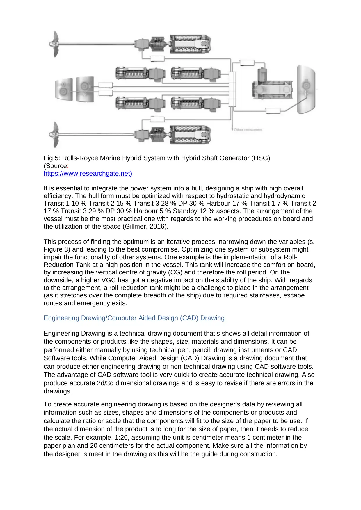
Fig 5: Rolls-Royce Marine Hybrid System with Hybrid Shaft Generator (HSG)
(Source:
https://www.researchgate.net)
It is essential to integrate the power system into a hull, designing a ship with high overall
efficiency. The hull form must be optimized with respect to hydrostatic and hydrodynamic
Transit 1 10 % Transit 2 15 % Transit 3 28 % DP 30 % Harbour 17 % Transit 1 7 % Transit 2
17 % Transit 3 29 % DP 30 % Harbour 5 % Standby 12 % aspects. The arrangement of the
vessel must be the most practical one with regards to the working procedures on board and
the utilization of the space (Gillmer, 2016).
This process of finding the optimum is an iterative process, narrowing down the variables (s.
Figure 3) and leading to the best compromise. Optimizing one system or subsystem might
impair the functionality of other systems. One example is the implementation of a Roll-
Reduction Tank at a high position in the vessel. This tank will increase the comfort on board,
by increasing the vertical centre of gravity (CG) and therefore the roll period. On the
downside, a higher VGC has got a negative impact on the stability of the ship. With regards
to the arrangement, a roll-reduction tank might be a challenge to place in the arrangement
(as it stretches over the complete breadth of the ship) due to required staircases, escape
routes and emergency exits.
Engineering Drawing/Computer Aided Design (CAD) Drawing
Engineering Drawing is a technical drawing document that’s shows all detail information of
the components or products like the shapes, size, materials and dimensions. It can be
performed either manually by using technical pen, pencil, drawing instruments or CAD
Software tools. While Computer Aided Design (CAD) Drawing is a drawing document that
can produce either engineering drawing or non-technical drawing using CAD software tools.
The advantage of CAD software tool is very quick to create accurate technical drawing. Also
produce accurate 2d/3d dimensional drawings and is easy to revise if there are errors in the
drawings.
To create accurate engineering drawing is based on the designer’s data by reviewing all
information such as sizes, shapes and dimensions of the components or products and
calculate the ratio or scale that the components will fit to the size of the paper to be use. If
the actual dimension of the product is to long for the size of paper, then it needs to reduce
the scale. For example, 1:20, assuming the unit is centimeter means 1 centimeter in the
paper plan and 20 centimeters for the actual component. Make sure all the information by
the designer is meet in the drawing as this will be the guide during construction.
⊘ This is a preview!⊘
Do you want full access?
Subscribe today to unlock all pages.
Trusted by 1+ million students worldwide
1 out of 27
Related Documents


Your All-in-One AI-Powered Toolkit for Academic Success.
+13062052269
info@desklib.com
Available 24*7 on WhatsApp / Email
![[object Object]](/_next/static/media/star-bottom.7253800d.svg)
Unlock your academic potential
Copyright © 2020–2026 A2Z Services. All Rights Reserved. Developed and managed by ZUCOL.