Naval Engineering: Applying Principles to Solve Real-World Problems
VerifiedAdded on 2023/04/22
|20
|4943
|281
Report
AI Summary
This report examines the application of engineering principles to solve various problems within naval engineering. It begins with an overview of how engineering has transformed sea travel and navigation, highlighting advancements in ship design and technology. The report then delves into specific challenges, such as the problem of partial loading in cargo tanks, focusing on sloshing effects in LNG tanks and the improvements made to mitigate these issues. The report also discusses the benefits of parallel operation of power generators, detailing the advantages in terms of reliability, expandability, flexibility, and cost-effectiveness. Furthermore, it includes a discussion on ship power load, the calculation of power requirements, and the decision-making process for determining the number of diesel generators required, considering factors like sailing, maneuvering, and harbor conditions. The report also touches upon the use of direct current (DC) generators. This comprehensive analysis provides insights into the practical application of engineering principles in addressing real-world problems in the naval sector.

APPLY ENGINEERING PRINCIPLES TO SOLVE PROBLEMS
[Author Name(s), First M. Last, Omit Titles and Degrees]
[Institutional Affiliation(s)]
[Author Name(s), First M. Last, Omit Titles and Degrees]
[Institutional Affiliation(s)]
Paraphrase This Document
Need a fresh take? Get an instant paraphrase of this document with our AI Paraphraser

Introduction
Engineering principles are applied in almost all aspects of life. Travel, farming or even teaching
have all benefited from engineering. Travel through sea has always been dependent on
engineering. Traditional sea farers depended on manpower and wind for propulsion. This has
changed over the past two centuries. Navigation was also based largely on human knowledge of
the stars to provide direction (Mallam & Lundh, 2016). Over the years, sea navigation has
become more mechanized. It is no longer dependent on the skills of one person but rather on the
ability to read instruments and act upon them.
Naval vessels have improved their overall performance by taking advantage of engineering. In
the past there was no navigation but current navigation tools have allowed sailors to know their
environment even without looking outside their vessels. The engineering of the bodies of ships
have also become more efficient compared to the past. This has consequently seen a growth in
the number of vessels made for transport of cargo, luxury cruise ships or commercial fishing
expeditions. All these vessels have benefited from improved technology. In the ship yards I have
visited, I have learnt a lot about how ships are made and how technologies have improved over
the years.
From the design to the launching of the ship, there are steps followed to ensure that the ship is up
to the required standard (Jafarzadeh, Paltrinieri, Utne & Ellingsen, 2017). Quality control
departments are there to ensure that every step of construction conforms to the safety standards.
Without a set standard, there are bound to be failures in the fabrication process. The ships have
to be built to withstand a lot of emphasis on durability and safety. Investments into ship building
are always bound to high. Ships built should be able to last through any kind of weather.

The construction process incorporates many fields of engineering. This includes the structural,
mechanical and electrical parts. All of these discipline work together to deliver quality and
reliable ships. They are dependent on each other and therefore produce the best quality desired.
Each skill has its own role to play. Need for stronger ships have increased and made life easier
for cargo transport and mass transit of people.
Naval engineering
Naval engineering applies a lot of scientific principles. Ship building incorporates mechanical
and electronic principles. The ship is driven by mechanical power, mainly powered by fuels. The
controls are mainly done by electronic circuit boards and have a feedback mechanism. Ship
building also encompasses civil and structural engineering. Depending on the size of the ship, the
type of material used has to vary (Platzer & Sarigul-Klijn, 2018). The ship propulsion system is a
crucial part of the ship. The stability of the ship and the strength also feature prominently in the
design consideration of the ship. The power supply systems are also an important consideration
in the design of the ship.
Ship construction yards are made to resemble docks, where a ship can be tested on completion.
The ship construction process takes a long time and therefore it is necessary for construction to
be completely flawless. One fault in any sector can lead to fatalities once the ship leaves the
dock. The layout of a ship yard, just like any other workings, put serious consideration into
safety and ease of doing work. Safety covers the positioning of the work pieces, demarcation of
work space and fire fighting equipment as required by safety standards (Sun et al., 2019).
⊘ This is a preview!⊘
Do you want full access?
Subscribe today to unlock all pages.
Trusted by 1+ million students worldwide
Problem of partial loading of cargo tanks and filling limits
Within a range of the levels of tank filling, the rolling as well as pitching movements of the ship
at seas as well as the liquid free-surface effect may result in the liquid moving within the tank.
There is a possibility of movement of considerable liquid resulting in high impact pressure on the
surface of the tank. This effect is referred to as sloshing and may lead to structural damage.
Sloshing is a challenge which has effects on the membrane constructed tanks. The same sloshing
impacts are not experienced by the independent containment systems including the IHI prismatic
design were well as the spherical Moss design. Partial loading at any level of tank filling comes
from the design of Moss design tanks offering them distinct advantages over the membrane
containment systems during handling of ship trades as well as offshore loading (Mallam, Lundh
& MacKinnon, 2015).
This has taken on an even bigger importance with the operators looking for the operational
flexibility of partial cargo loading alongside the growing preference for containment systems of
membrane type. Liquefied gas carrier is transmitted at about-160⁰C. As the low-filling condition
generates progressive waves called hydraulic jumps, the partially-loaded carriers may exhibit
high dynamic loads.
As a result, sloshing owing to partial fulfilling has been carefully examined. Features unique to
lLNG among them compressibility of the entrapped gas, low temperature, hydrodynamic
interaction between the containment system and liquid as well as dynamic material features
challenge the strength of the vessel and may need extra reinforcement at the critical regions.
Such areas include the tank structure, insulation system as well as pump tower that act as the
Paraphrase This Document
Need a fresh take? Get an instant paraphrase of this document with our AI Paraphraser

connection for cargo handling to the hill as well as the base support (McKay, Stiny & de
Pennington, 2016).
The sloshing motion experienced in an LNG tanks at the low levels of filling tends to be quite
dissimilar from the one that is encounter when the levels of filling are high.
The front of the hydraulic pump tends to be steeper when the tank is experiencing large motion
hence the development of a breaking wave. A large impact may be generated in case the
hydraulic pump knocks the bulkhead prior to breaking. The uniform speed of the hydraulic jump
as well leads into a strong and large drag force on the pump tower’s lower pump as well as the
supporting system. Sloshing impacts are experienced when a sudden change in the wet surface is
experienced as a result of the motion of the liquid in the tank. In a compartment that is partially
filled, a broader region of the tank wall tends to be vulnerable to the cargo impact.
Improvements and design modifications
The main concerns are the high dynamic loads as well as the impact of sloshing pressure on the
system of insulation and structure of the tank in a membrane –type vessel. Borrowing from the
experience gathered on the initial LNG ships put into work and from enormous quantity of
model tests as well as computer analyses as there have been numerous improvements to control
the sloshing impact. The height of chamfer at the side of the top was increased and the insulation
boxes as the top tank reinforced using tolerable slashing impact in the entirely laden condition
Keane, R. G., Deschamps & Maguire, 2016. There has been a significant improvement in the
construction n as well as design of the membrane alongside supporting insulation structures.

Parallel Operation of Power Generators
Using generators that are similar or at least having the same rating of output as well as alternator
pitch is one of the simplest ways of setting up a parallel system. Still, having two or more
generators that are of variable output is yet another approach in backing up the power
requirements. In either of the cases, the generators may be connected in parallel having
paralleling switchgear in order to attain maximum output during peak need or the desired
minimal output at some other times.
Parallel standby power systems have remained to be significantly advantageous in comparison
with large single generator units. Nevertheless the implementation of the systems has since been
limited to big projects or applications that are mission critical owing to the constraint of high
complexity levels, space and cost that are associated with the setup and maintenance (Niese,
Kana & Singer, 2015). Among the benefits of parallel operation generators over single large
generator units include:
Reliability: A greater reliability is provided by the redundancy interest that is in parallel
operation of numerous generators for critical loads. In case of failure of one of the units,
redistribution of the critical loads is done across all the other remaining functional units within
the system on a priority basis.
⊘ This is a preview!⊘
Do you want full access?
Subscribe today to unlock all pages.
Trusted by 1+ million students worldwide
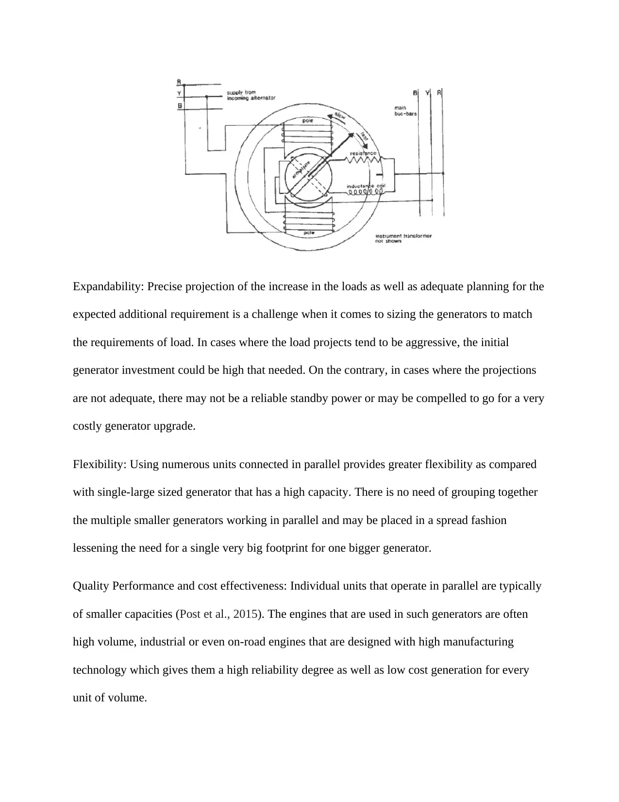
Expandability: Precise projection of the increase in the loads as well as adequate planning for the
expected additional requirement is a challenge when it comes to sizing the generators to match
the requirements of load. In cases where the load projects tend to be aggressive, the initial
generator investment could be high that needed. On the contrary, in cases where the projections
are not adequate, there may not be a reliable standby power or may be compelled to go for a very
costly generator upgrade.
Flexibility: Using numerous units connected in parallel provides greater flexibility as compared
with single-large sized generator that has a high capacity. There is no need of grouping together
the multiple smaller generators working in parallel and may be placed in a spread fashion
lessening the need for a single very big footprint for one bigger generator.
Quality Performance and cost effectiveness: Individual units that operate in parallel are typically
of smaller capacities (Post et al., 2015). The engines that are used in such generators are often
high volume, industrial or even on-road engines that are designed with high manufacturing
technology which gives them a high reliability degree as well as low cost generation for every
unit of volume.
Paraphrase This Document
Need a fresh take? Get an instant paraphrase of this document with our AI Paraphraser
Ease of serviceability and maintenance: The individual units may be dismembered and service in
case of a breakdown or the need of maintenance of a generator in the system without necessarily
having to interfering with the functioning of the remaining units. The redundancy inherent in a
parallel system offers multiple protection layers besides ensuring uninterrupted power supply of
the critical units.
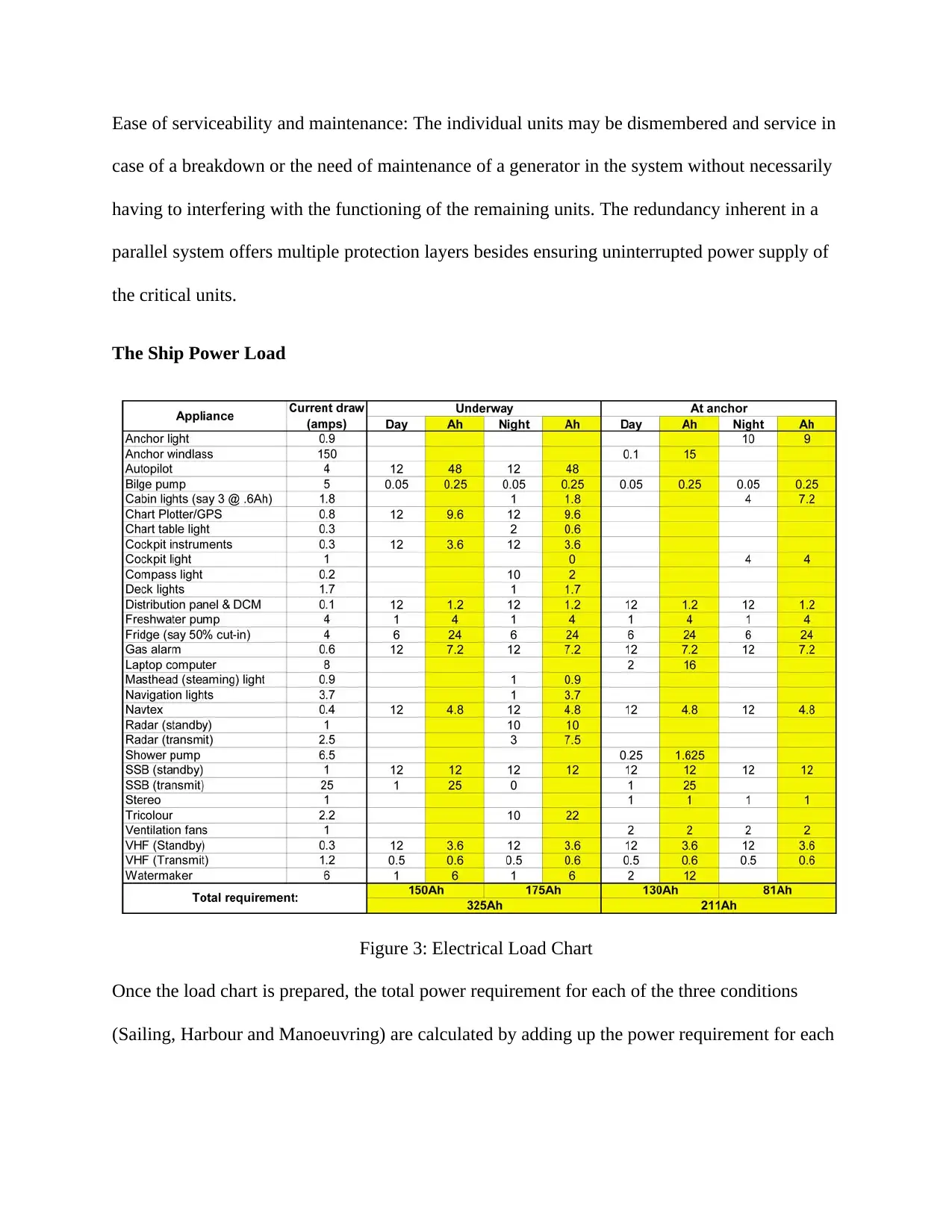
The Ship Power Load
Figure 3: Electrical Load Chart
Once the load chart is prepared, the total power requirement for each of the three conditions
(Sailing, Harbour and Manoeuvring) are calculated by adding up the power requirement for each
case of a breakdown or the need of maintenance of a generator in the system without necessarily
having to interfering with the functioning of the remaining units. The redundancy inherent in a
parallel system offers multiple protection layers besides ensuring uninterrupted power supply of
the critical units.
The Ship Power Load
Figure 3: Electrical Load Chart
Once the load chart is prepared, the total power requirement for each of the three conditions
(Sailing, Harbour and Manoeuvring) are calculated by adding up the power requirement for each

component for each of the conditions (follow calculation below). Once this is clear, we will now
refer to calculation below to understand how the total number of diesel generators is decided.
Required generator capacity
1. Sailing Condition
At SAILING total sea load in kW=1058.62
4*500 kW
Percentage of loading on each generator=58.26%
Manoeuvring condition
At Manoeuvring total load in kW=1582.69
5*500 kW
Percentage of loading in each generator=52.26%
Harbour condition
At Harbour total load in kW=786.32
2*500 kW
Percentage of Loading on generator=54.69%
The two rules to be followed in deciding upon the number of generators are:
⊘ This is a preview!⊘
Do you want full access?
Subscribe today to unlock all pages.
Trusted by 1+ million students worldwide

If more than one generator is operating in any condition, both the generators should share
equal amount of load.
The load on each generator in any of the three conditions should not be more than 70
percent of the rated power of the generator. (Or, the maximum rating of each generator
is decided based upon the condition that seventy percent of the maximum rating is more
than the load on the generator in any of the three conditions) (Song & Huang, 2018)
One additional generator should always be included, which is for standby purpose. Note
that this standby generator will not share the load in any of the above three conditions
unless any of the working generators are out of order. So, the standby generator is not
included in the above calculation, but it is usually of the same rating as of the other
generators.
This process is iterated by varying power ratings and varying number of generators until the
above first two conditions are satisfied, and a situation like the one in calculation below is
obtained. It is advised that you analyse the first two conditions using the above figure to
understand it in first hand.
Direct current (DC) Generator
Paraphrase This Document
Need a fresh take? Get an instant paraphrase of this document with our AI Paraphraser

Recommendations
More often than not, each of the individual generators that are connected in parallel is composed
of between four to six microcontrollers which are together hardwired. The complexity of the
generators increases should the individual generators be manufactured by various vendors as
well as the controllers are dependent on the combination of analog and digital technologies.
Setting up a large capacity generator in parallel takes between three to four weeks and the
following recommendations are provided:
Speed control: Every individual generator works at its own stipulated speed and frequency of the
engine. The speeds of the engines are locked into the general speed of the whole system when
the individual generators are jointly coupled. The speed of the engine is determined by the load
that is shared by each of the generators and in case of a parallel system the whole load is shared
by all the linked generators.
Gunset controller: The controller is installed for checking of the various engine parameters as
well as the alternators of every unit in the system. Scheduling and load control generators going
off/on may as well be done using some of the newer and digital controllers that are available
(Andrews, Kana, Hopman & Romanoff, 2018). The installation of each of the controllers has to
be done in such a way that they are able to control the operation of the individual generators as
well as have to be synchronised with the functioning of the parallel system that is controlled by
the main controller. As a result of the simultaneous operation of various controllers, a lot of
electric noise is generated by the parallel systems which results in disturbance and such systems
are often susceptible to temporary collapse. This calls for the need of frequent supervision to
ensure consistent power supply during instances of power failures.

The use of integrated paralleling aids in the reduction of the noise and improved the performance
of the parallel power unit. Still such controller are play and plug devices such that in case of
failure of any of them, it is simply unplugged and replaced using the available spare parts.
Synchronization: The phase of each of the generators to the entire systems should be
synchronized. The use of automatic synchronizing equipment is recommended.
Thermodynamics principles
Making the correct calculations on the refrigeration requirements of a cold store call for a good
deal of experience which should just be carried out by qualified personnel. The calculation
below, even though not to completion, acts to serve two roles. It enables making of similar
calculation for the cold store of the shop and thus coming up with estimated requirements for
refrigeration. It as well aids in appreciating the number of factors which have to be considered in
the calculation of the heat load alongside giving some idea regarding their relative importance.
A significant heat load that will be omitted in this calculation will be the heat load that is as a
result of solar radiation. This factor relies on numerous conditions that are related with the
construction method as well as the location of the store (Karczewski & Kozak, 2017). In some
instances, the solar heat load can be significant while in others, there may be need to take
precaution in reducing the effect
Cold store refrigeration load
Assuming the specifications:
Store temperature= -30⁰C
Dimensions 20 m by 10 m by 5 m=1000m3
⊘ This is a preview!⊘
Do you want full access?
Subscribe today to unlock all pages.
Trusted by 1+ million students worldwide
1 out of 20

Your All-in-One AI-Powered Toolkit for Academic Success.
+13062052269
info@desklib.com
Available 24*7 on WhatsApp / Email
![[object Object]](/_next/static/media/star-bottom.7253800d.svg)
Unlock your academic potential
Copyright © 2020–2026 A2Z Services. All Rights Reserved. Developed and managed by ZUCOL.