Network Topologies, Architectures, and Physical Layer Report
VerifiedAdded on 2021/04/16
|40
|10002
|305
Report
AI Summary
This report provides a comprehensive overview of network architecture, delving into key concepts such as peer-to-peer and client-server models, and comparing their advantages and disadvantages. It explores various network topologies, including bus, ring, mesh, and star topologies, analyzing their suitability for different architectural designs. The report also examines the physical layer, discussing guided and unguided media like twisted pair cables, coaxial cables, fiber-optic cables, radio waves, microwaves, and Wi-Fi. It includes diagrams of LAN and MAN, and concludes with a comparison of Internet Service Providers (ISPs) such as Sri Lanka Telecom (SLT) and Dialog, covering their growth and network infrastructure. The report highlights the importance of network architecture in today's world and the impact of network evolution on daily life.
Contents
1. Executive summary (Part-01)................................................................................................3
2. Introduction............................................................................................................................3
3. Introduction to network..........................................................................................................3
LAN........................................................................................................................................3
MAN......................................................................................................................................4
WAN.......................................................................................................................................4
4. Introduction to network architecture......................................................................................5
1. Peer-to-Peer architecture or P2P.....................................................................................5
Suitable topology for Peer to Peer..................................................................................7
2. Client-Server Architecture..............................................................................................7
Suitable topology for client-server architecture............................................................8
5. Comparison between peer to peer and client-server..............................................................9
6. Physical Layer........................................................................................................................9
I. Guided Media...................................................................................................................10
1. Twisted Pair Cables................................................................................................10
2. Coaxial cable..........................................................................................................10
3. Fiber-Optic cable...................................................................................................10
II. Unguided Media..............................................................................................................11
1. Radio waves...........................................................................................................11
2. Microwaves............................................................................................................11
3. Infrared...................................................................................................................11
4. Wi-Fi..............................................................................................................................11
7. Network Topology................................................................................................................11
I. Importance of network topology...................................................................................12
II. Classification of network topologies.........................................................................12
A. Bus Topology.........................................................................................................12
B. Ring topology........................................................................................................13
C. Mesh topology...........................................................................................................14
D. Start topology............................................................................................................16
Comparison between Mesh and Start topology....................................................................17
8. Conclusion............................................................................................................................17
References................................................................................................................................18
1 | P a g e
Paraphrase This Document
Need a fresh take? Get an instant paraphrase of this document with our AI Paraphraser
1. Executive summary ( Part-02 )............................................................................................19
2. Introduction..........................................................................................................................19
3. LAN......................................................................................................................................19
Advantage of LAN...............................................................................................................19
Disadvantage of LAN..........................................................................................................19
4. Wi-Fi....................................................................................................................................20
Advantages...........................................................................................................................20
Disadvantages......................................................................................................................20
5. Comparison..........................................................................................................................20
7. ISP........................................................................................................................................21
1. Sri Lanka Telecom...........................................................................................................21
Growth of SLT................................................................................................................22
2. Dialog...............................................................................................................................22
Growth of network.........................................................................................................22
8. ISP comparison....................................................................................................................23
9. Conclusion............................................................................................................................23
References................................................................................................................................23
Table of figures
Figure 1 LAN Diagram..............................................................................................................4
Figure 2 MAN Diagram.............................................................................................................4
Figure 3 MAN Diagram.............................................................................................................5
Figure 4 Peer to Peer Architecture.............................................................................................6
Figure 5 Client-Server Architecture...........................................................................................8
Figure 6 Transmission Media Table.........................................................................................10
Figure 7 Bus Topology.............................................................................................................12
Figure 8 Ring Topology...........................................................................................................14
Figure 9 Mesh Topology..........................................................................................................15
Figure 10 Star Topology...........................................................................................................16
Figure 11 Logo of SLT.............................................................................................................21
Figure 12 Logo of Dialog.........................................................................................................22
2 | P a g e
1. Executive summary (Part-01)
This report provides information about the main aspect of Network architecture, the physical
layer and its design and network topologies. This report include the information about
network architecture such as peer to peer and client-server, advantage and disadvantage of
these architectures, uses of network topology and comparison between them.
2. Introduction
In today’s world network becomes one of the most important and core part of human life.
Most of don’t even realize how network is having impact in our daily life. Our life just
changed dramatically in last decades because of the evolution of the networks. According to
the statistics, nowadays 55.1 percentage of world population has internet access, which is
more than 4 billion. This massive internet is also a network. If you ask how much impact we
have with network is? The best answer is think a day without WhatsApp, Facebook, Twitter,
Call or anything that you do with the mobile or laptops. That’s the disaster that every human
being can face in modern world. The world economy will fall and many terrible things will
happen because nowadays we can’t survive without network in this progressed world.
3. Introduction to network
In simple words computer network is interconnection between two or more computers or
devices, in order to share the internet, peripheral devices such as printer, scanner, etc… In
order to connect to network we need to have network components such as Network Interface
Card, Hub, Switch, Router and etc.… There are many types of network out there such as
1. LAN
2. MAN
3. WAN
To get to know about network topologies and all, we need to have short introduction about
these network types.
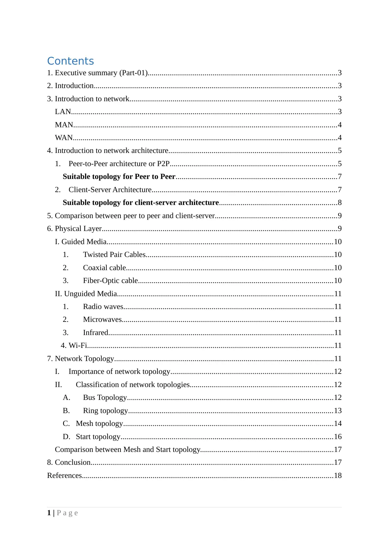
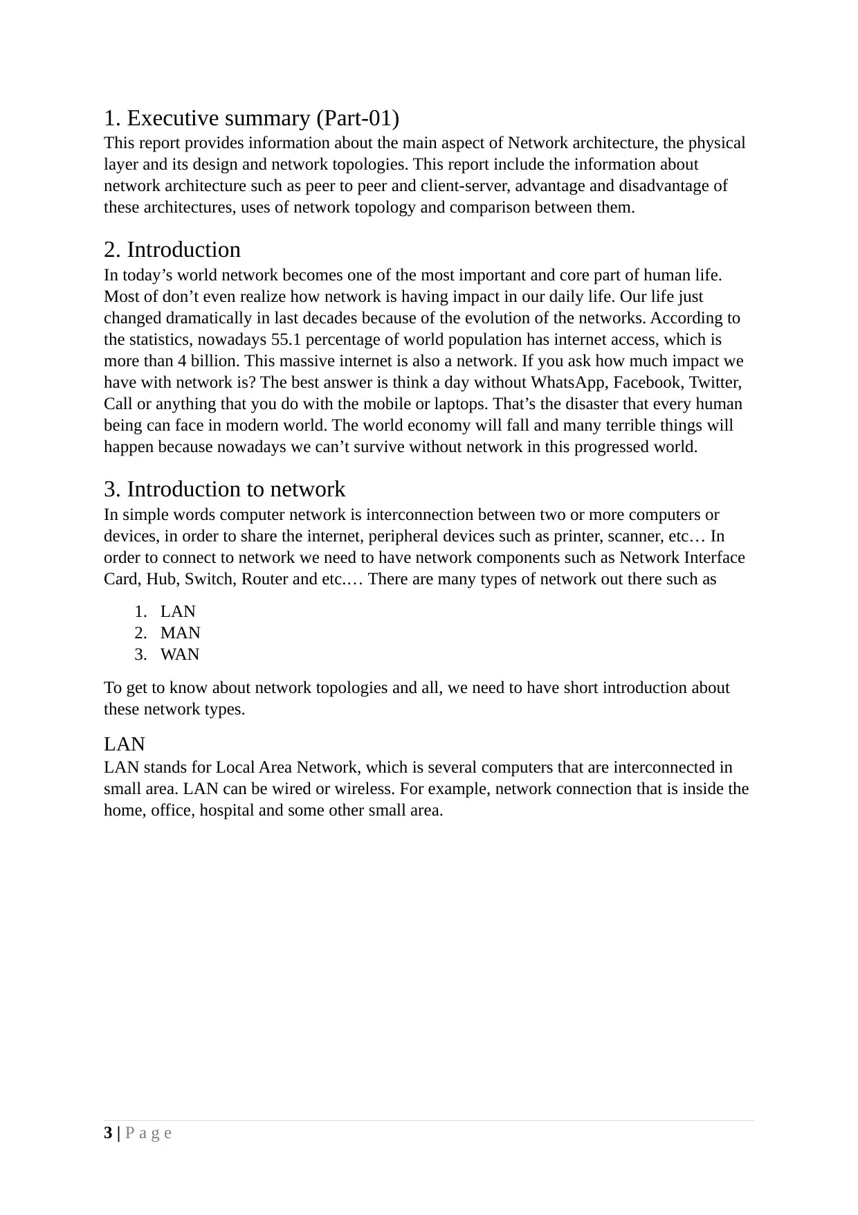
LAN
LAN stands for Local Area Network, which is several computers that are interconnected in
small area. LAN can be wired or wireless. For example, network connection that is inside the
home, office, hospital and some other small area.
3 | P a g e
This report provides information about the main aspect of Network architecture, the physical
layer and its design and network topologies. This report include the information about
network architecture such as peer to peer and client-server, advantage and disadvantage of
these architectures, uses of network topology and comparison between them.
2. Introduction
In today’s world network becomes one of the most important and core part of human life.
Most of don’t even realize how network is having impact in our daily life. Our life just
changed dramatically in last decades because of the evolution of the networks. According to
the statistics, nowadays 55.1 percentage of world population has internet access, which is
more than 4 billion. This massive internet is also a network. If you ask how much impact we
have with network is? The best answer is think a day without WhatsApp, Facebook, Twitter,
Call or anything that you do with the mobile or laptops. That’s the disaster that every human
being can face in modern world. The world economy will fall and many terrible things will
happen because nowadays we can’t survive without network in this progressed world.
3. Introduction to network
In simple words computer network is interconnection between two or more computers or
devices, in order to share the internet, peripheral devices such as printer, scanner, etc… In
order to connect to network we need to have network components such as Network Interface
Card, Hub, Switch, Router and etc.… There are many types of network out there such as
1. LAN
2. MAN
3. WAN
To get to know about network topologies and all, we need to have short introduction about
these network types.
LAN
LAN stands for Local Area Network, which is several computers that are interconnected in
small area. LAN can be wired or wireless. For example, network connection that is inside the
home, office, hospital and some other small area.
3 | P a g e
⊘ This is a preview!⊘
Do you want full access?
Subscribe today to unlock all pages.
Trusted by 1+ million students worldwide
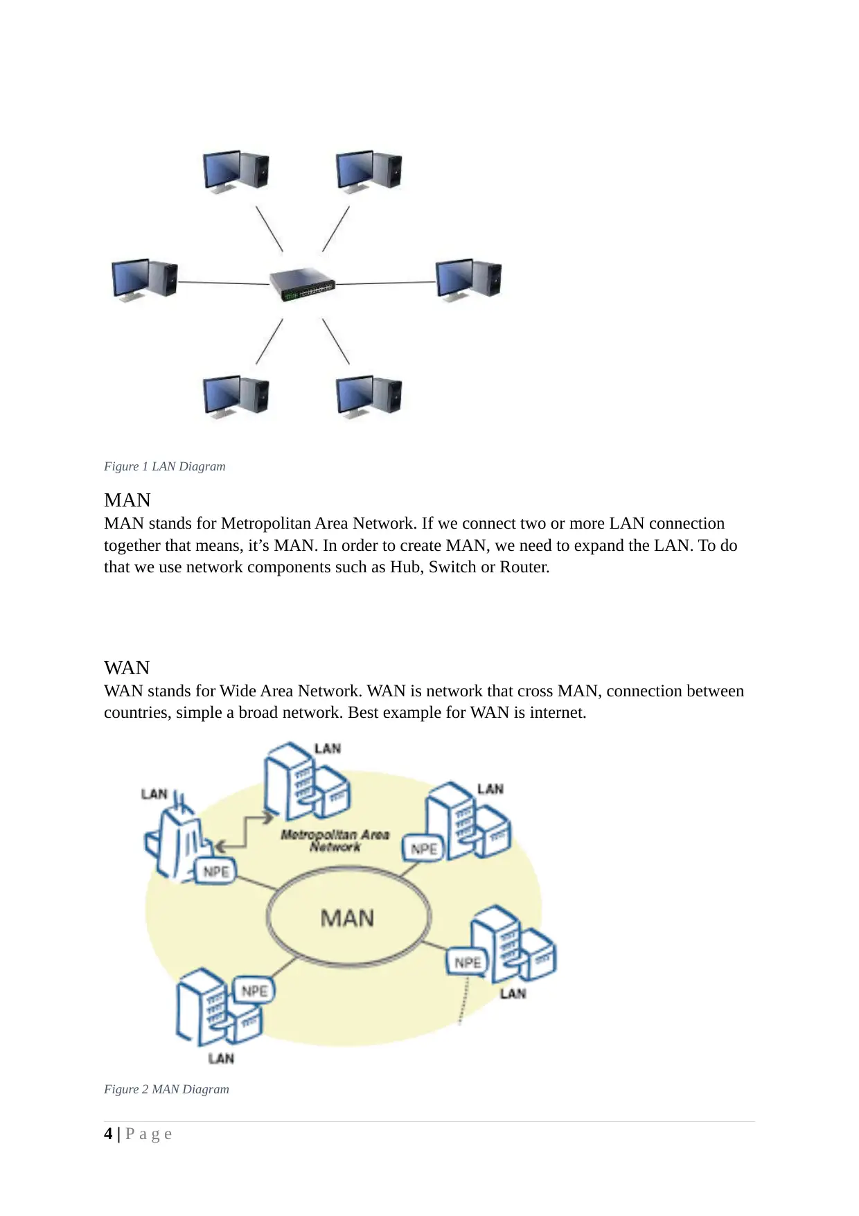
Figure 1 LAN Diagram
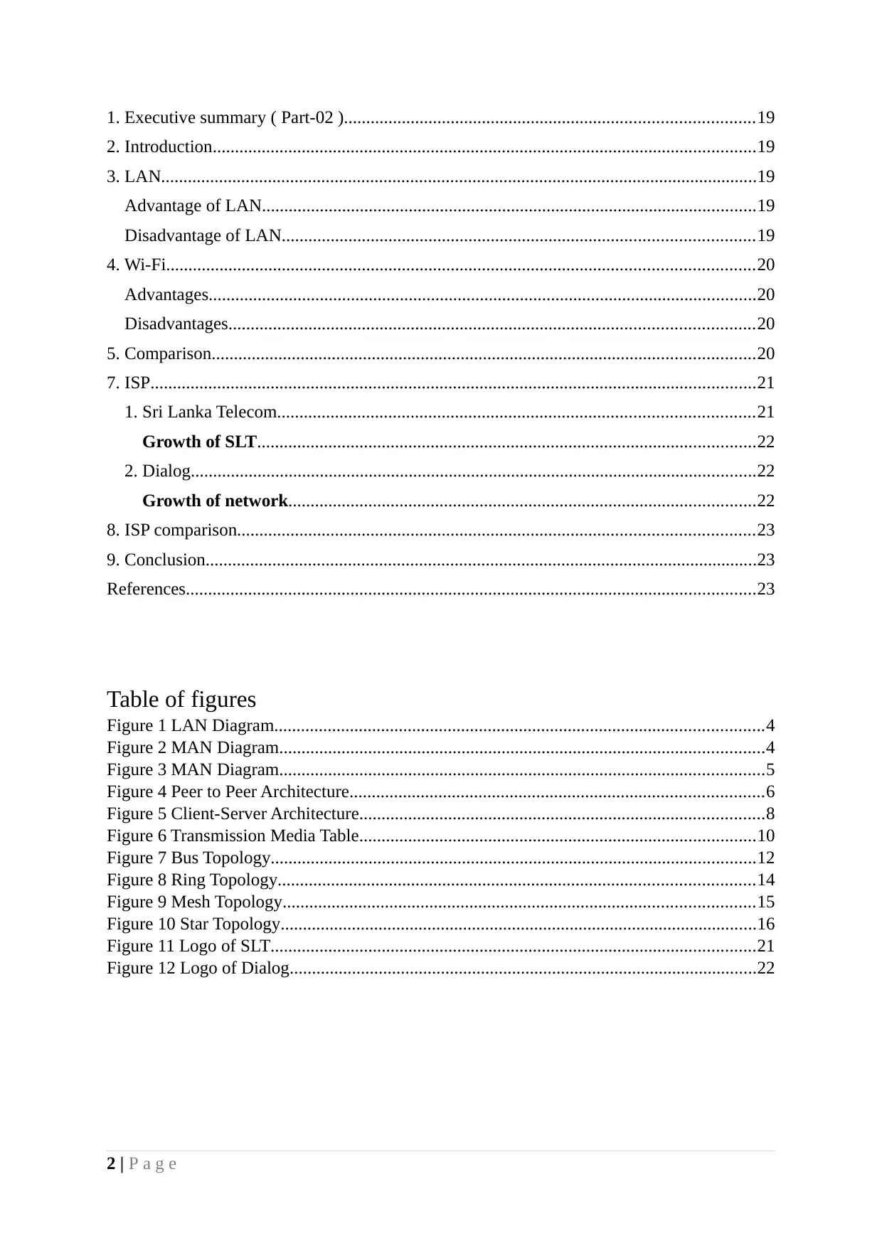
MAN
MAN stands for Metropolitan Area Network. If we connect two or more LAN connection
together that means, it’s MAN. In order to create MAN, we need to expand the LAN. To do
that we use network components such as Hub, Switch or Router.
WAN
WAN stands for Wide Area Network. WAN is network that cross MAN, connection between
countries, simple a broad network. Best example for WAN is internet.
Figure 2 MAN Diagram
4 | P a g e
Paraphrase This Document
Need a fresh take? Get an instant paraphrase of this document with our AI Paraphraser
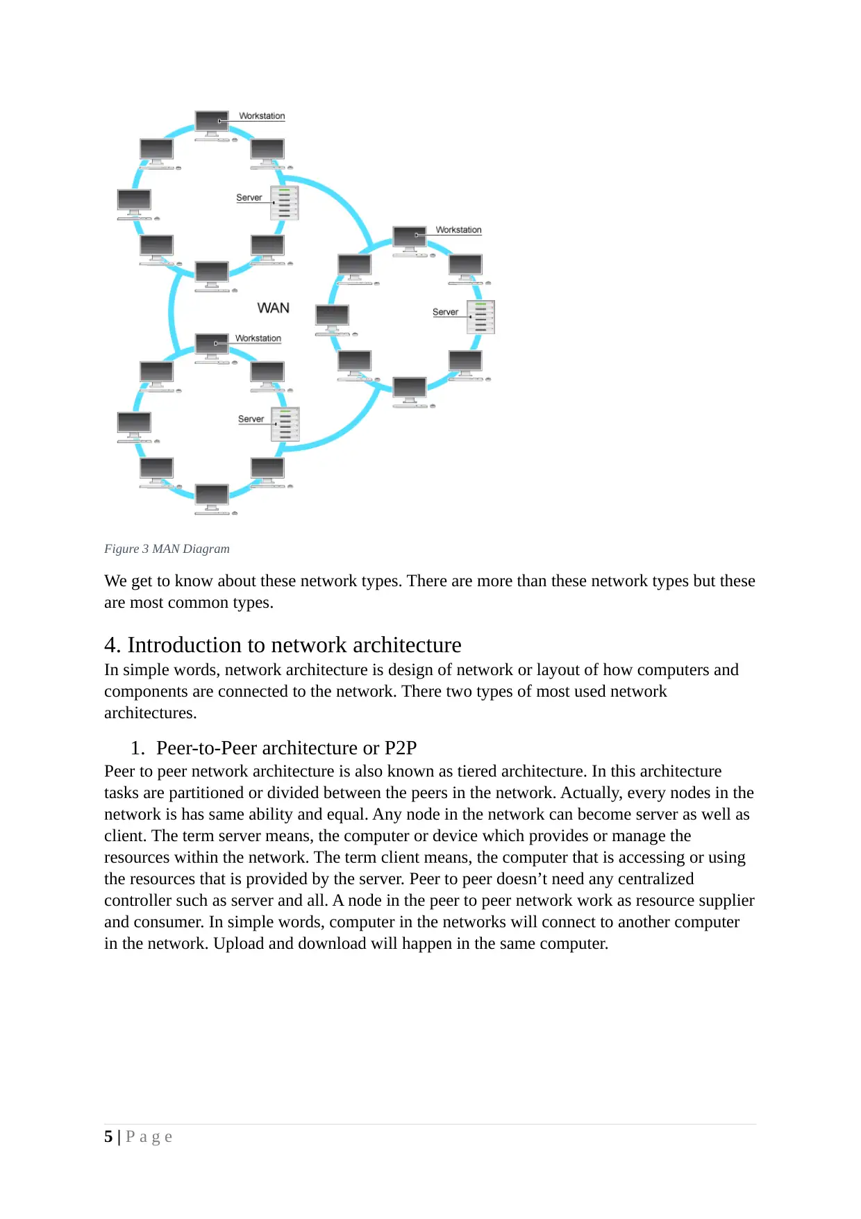
Figure 3 MAN Diagram
We get to know about these network types. There are more than these network types but these
are most common types.
4. Introduction to network architecture
In simple words, network architecture is design of network or layout of how computers and
components are connected to the network. There two types of most used network
architectures.
1. Peer-to-Peer architecture or P2P
Peer to peer network architecture is also known as tiered architecture. In this architecture
tasks are partitioned or divided between the peers in the network. Actually, every nodes in the
network is has same ability and equal. Any node in the network can become server as well as
client. The term server means, the computer or device which provides or manage the
resources within the network. The term client means, the computer that is accessing or using
the resources that is provided by the server. Peer to peer doesn’t need any centralized
controller such as server and all. A node in the peer to peer network work as resource supplier
and consumer. In simple words, computer in the networks will connect to another computer
in the network. Upload and download will happen in the same computer.
5 | P a g e
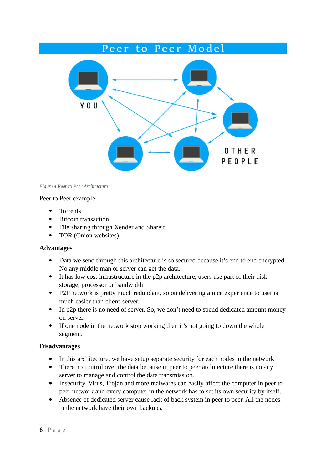
Figure 4 Peer to Peer Architecture
Peer to Peer example:
Torrents
Bitcoin transaction
File sharing through Xender and Shareit
TOR (Onion websites)
Advantages
Data we send through this architecture is so secured because it’s end to end encrypted.
No any middle man or server can get the data.
It has low cost infrastructure in the p2p architecture, users use part of their disk
storage, processor or bandwidth.
P2P network is pretty much redundant, so on delivering a nice experience to user is
much easier than client-server.
In p2p there is no need of server. So, we don’t need to spend dedicated amount money
on server.
If one node in the network stop working then it’s not going to down the whole
segment.
Disadvantages
In this architecture, we have setup separate security for each nodes in the network
There no control over the data because in peer to peer architecture there is no any
server to manage and control the data transmission.
Insecurity, Virus, Trojan and more malwares can easily affect the computer in peer to
peer network and every computer in the network has to set its own security by itself.
Absence of dedicated server cause lack of back system in peer to peer. All the nodes
in the network have their own backups.
6 | P a g e
⊘ This is a preview!⊘
Do you want full access?
Subscribe today to unlock all pages.
Trusted by 1+ million students worldwide
Suitable topology for Peer to Peer
Mesh topology is suitable topology for Peer to Peer architecture. There are several reasons for
that.
In mesh topology each and every computer is interconnected with another computer.
So far, in peer to peer also all nodes are connected with every other nodes. For some
special cases we can use partial mesh topology to connect a node to several nodes in
the network
In mesh topology we don’t have any centralized server in the network which is same
for the peer to peer architecture. There is no any centralized device in peer to peer
architecture.
In peer to peer every node in the network is server and client in case using mesh
topology will make data transmission more effective because in mesh topology
multiple devices can transmit data simultaneously.
If a one node fail in the network that will not affect the whole segment in the peer to
peer in this case, using mesh topology will be more efficient.
2. Client-Server Architecture
There client-server model is one of the computer will act as server which will provide
resources and manage the network. Other computers or nodes that are connected to the
network will be client which request resources from server. In this architecture, Server
computer holds the core part because it’s providing the resources. Client can’t share their
resources in this architecture, they can request the resources from server computers.
Example for this client-server, the bank provide online banking or ATM services. Clients can
request these services such as, current bank balance, online money transfer, cash withdraw
and deposit and more… In this case bank is server and customer is client.
7 | P a g e
Paraphrase This Document
Need a fresh take? Get an instant paraphrase of this document with our AI Paraphraser
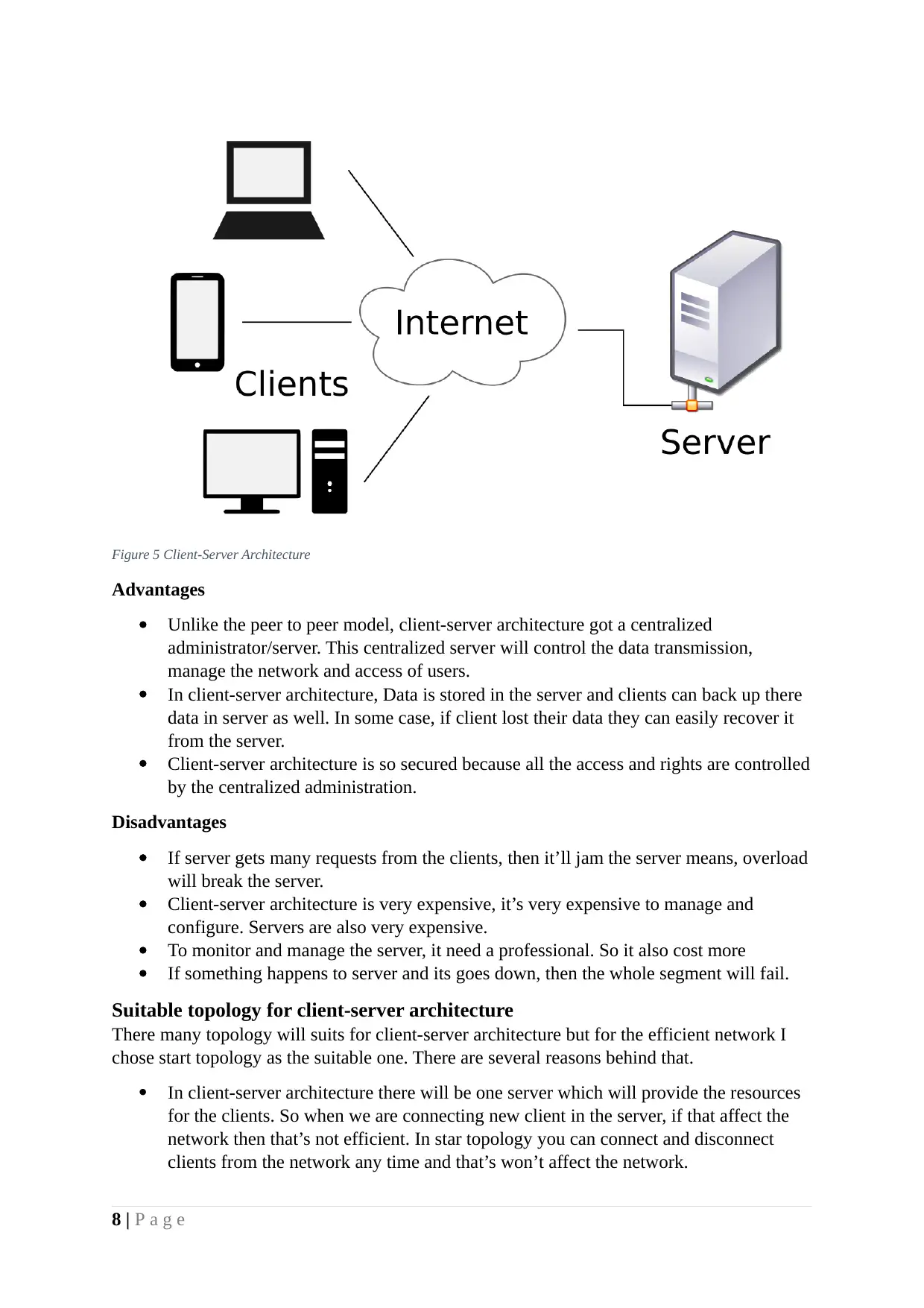
Figure 5 Client-Server Architecture
Advantages
Unlike the peer to peer model, client-server architecture got a centralized
administrator/server. This centralized server will control the data transmission,
manage the network and access of users.
In client-server architecture, Data is stored in the server and clients can back up there
data in server as well. In some case, if client lost their data they can easily recover it
from the server.
Client-server architecture is so secured because all the access and rights are controlled
by the centralized administration.
Disadvantages
If server gets many requests from the clients, then it’ll jam the server means, overload
will break the server.
Client-server architecture is very expensive, it’s very expensive to manage and
configure. Servers are also very expensive.
To monitor and manage the server, it need a professional. So it also cost more
If something happens to server and its goes down, then the whole segment will fail.
Suitable topology for client-server architecture
There many topology will suits for client-server architecture but for the efficient network I
chose start topology as the suitable one. There are several reasons behind that.
In client-server architecture there will be one server which will provide the resources
for the clients. So when we are connecting new client in the server, if that affect the
network then that’s not efficient. In star topology you can connect and disconnect
clients from the network any time and that’s won’t affect the network.
8 | P a g e
In client-server architecture, there will be many clients. By choosing star topology for
architecture we can get safe from network fail because in most of the topology, if a
node in the network fails that’ll down the whole segment.
We can easily detect the faults in the network, in topology like bus it’s difficult to
figure the problems in the network.
In client-server architecture, server will store the data which is go through the
network. In that case, data is more secure in the star topology rather than other
topologies like bus and ring.
We can send the data simultaneously. It’s not possible in topologies like bus because
in that data flow is in one direction.
5. Comparison between peer to peer and client-server
Client-server architecture is built to operate the network that is based on centralized server
which will provide the resources to clients. In peer to peer all the computer or node that are
connected to the network can be server and client. This is the major difference between these
two architectures.
In client-server architecture, the centralized server will back up the data in its server but in
the peer to peer it doesn’t happen because peer to peer doesn’t have a database like in client-
server architecture. So on, peers need to have their own back up itself.
There is a case called “Bottle-Neck effect” which means, the capacity is limited by the
allocated amount of resources. This phenomenon is mostly could happen in client-server
architecture because in this model on server is providing all the clients. Bottleneck effect
chances are low in peer to peer.
In client-server architecture, server contains all the login information of clients itself. If a
client wants to connect to the server then they have to provide proper email and password but
in peer to peer, each and every nodes in the network need to have their own security such as
windows password for its security. There no any centralized devices to control the peers in
the network. In client-server architecture, there high chance to get the data when the
transmission is high compared to peer to peer. Peer to peer is direct connection, so far chance
of man in the middle attack is low.
6. Physical Layer
Below the physical layer is the place where transmission media is located and also it’s
controlled by the physical layer itself.
Transmission media is something that carry the information from sender to receiver. There
two type of transmission media.
9 | P a g e
⊘ This is a preview!⊘
Do you want full access?
Subscribe today to unlock all pages.
Trusted by 1+ million students worldwide
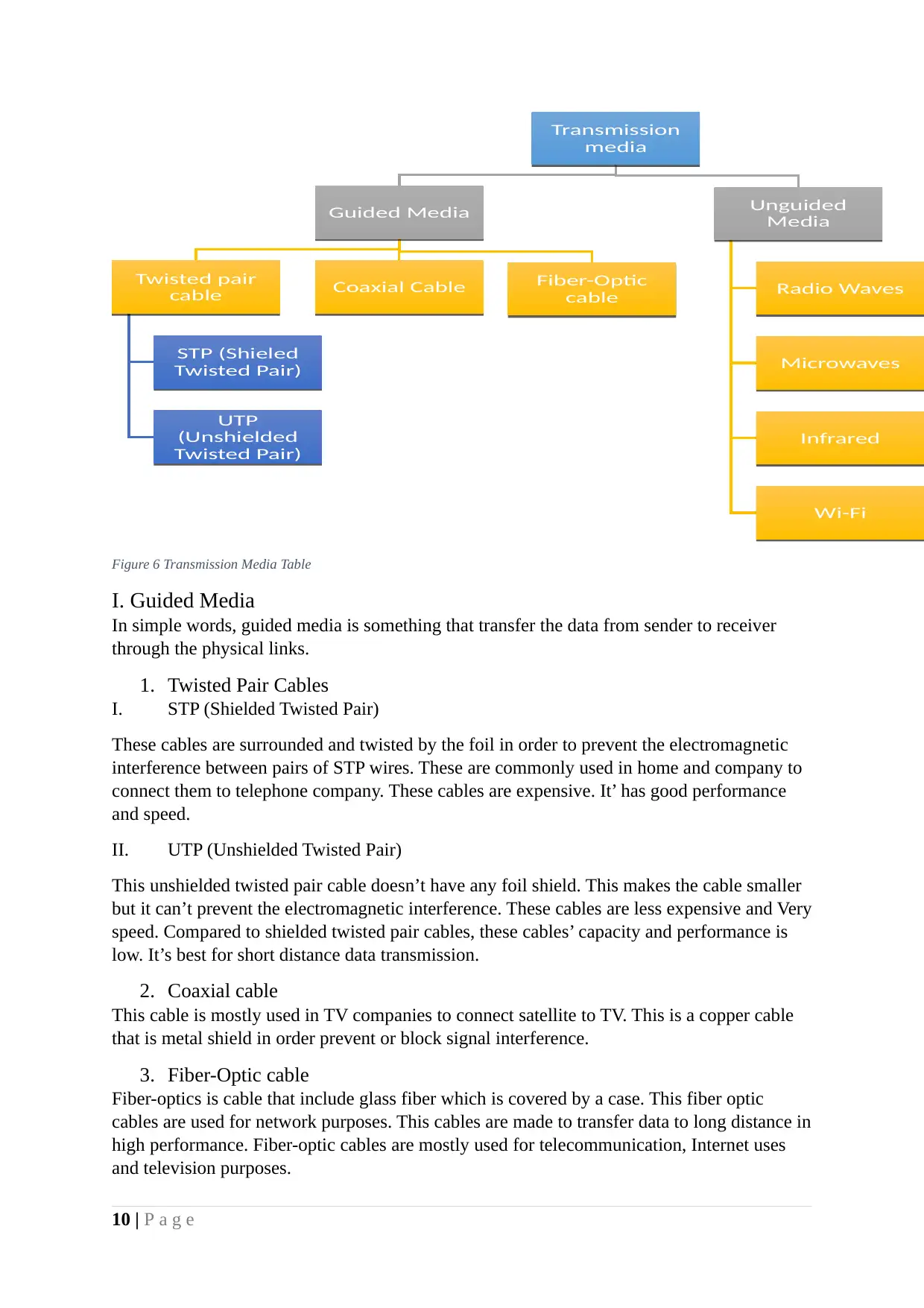
Figure 6 Transmission Media Table
I. Guided Media
In simple words, guided media is something that transfer the data from sender to receiver
through the physical links.
1. Twisted Pair Cables
I. STP (Shielded Twisted Pair)
These cables are surrounded and twisted by the foil in order to prevent the electromagnetic
interference between pairs of STP wires. These are commonly used in home and company to
connect them to telephone company. These cables are expensive. It’ has good performance
and speed.
II. UTP (Unshielded Twisted Pair)
This unshielded twisted pair cable doesn’t have any foil shield. This makes the cable smaller
but it can’t prevent the electromagnetic interference. These cables are less expensive and Very
speed. Compared to shielded twisted pair cables, these cables’ capacity and performance is
low. It’s best for short distance data transmission.
2. Coaxial cable
This cable is mostly used in TV companies to connect satellite to TV. This is a copper cable
that is metal shield in order prevent or block signal interference.
3. Fiber-Optic cable
Fiber-optics is cable that include glass fiber which is covered by a case. This fiber optic
cables are used for network purposes. This cables are made to transfer data to long distance in
high performance. Fiber-optic cables are mostly used for telecommunication, Internet uses
and television purposes.
10 | P a g eTransmission
media
Transmission
mediaGuided Media
Guided MediaTwisted pair
cable
Twisted pair
cableSTP (Shieled
Twisted Pair)
STP (Shieled
Twisted Pair)UTP
(Unshielded
Twisted Pair)
UTP
(Unshielded
Twisted Pair)Coaxial Cable
Coaxial CableFiber-Optic
cable Fiber-Optic
cableUnguided
Media
Unguided
MediaRadio Waves
Radio WavesMicrowaves
MicrowavesInfrared
InfraredWi-Fi
Wi-Fi
Paraphrase This Document
Need a fresh take? Get an instant paraphrase of this document with our AI Paraphraser
Fiber optic cables supports higher capacity of bandwidth. It can transmit the data for long
distance in high performance without losing its speed.
II. Unguided Media
Unlike guided media, unguided don’t use any sort of physical media to transfer data. It uses
electromagnetic signal as transmission medium.
1. Radio waves
In some case we have to pass our data to some other building, in the case our data have to
pass through the walls and all. One of the best way to transmit the data through the building
is radio waves. It’s easy and efficient because the antennas do have to be aligned for
transmission. Phones and FM radios are using this radio waves for the data transmission.
2. Microwaves
In order the transfer data via microwaves, the antennas should be aligned. Microwaves got
high frequency waves. These frequency is made by many transmitters. In phone we have
transmitter chip.
Mobile phones is also using microwaves for communication. Even for the television channel
distribution we use microwaves.
3. Infrared
This is used for short distance data transmission. In our daily life, we use remote to control
the TV. It also made by infrared. Wireless mouse and keyboard also using this infrared. This
infrared al penetrate through the wall.
4. Wi-Fi
The term Wi-Fi stands for wireless fidelity. Best way to understand the Wi-Fi is to home and
company or most of the public places support Wi-Fi now. To transmit wireless signal for Wi-
Fi, we need devices like router, smart phone or computer. Using Wi-Fi we can communicate
and transfer the data via wireless signals.
7. Network Topology
Network topology is the systematic and visual representation of network arrangement and
connection of nodes, connecting lines and wires.
There are two types of network topologies.
1. Physical topology
Physical topology is just like a map of network. It describes the workstation, cables and all
other components in the network visually. This physical topology is based on the physical
layer of the OSI model that we see before.
2. Logical topology
Logical topology is about how the information and data flows through the network. Logical
topology defines how data should transfer in the network. This defines the way signals react
with network and how nodes in the network communicate with each and another.
11 | P a g e
I. Importance of network topology
1. After the advent of network topology, the evolution in network field is very huge and
efficient.
2. By knowing about topologies will give good understanding in network field. People
will know how computer network will works? And importance of it also. Through
network topologies people will get better understanding in components like router,
cables and more.
3. Network topology is helping us to improve the performance and efficient of network.
4. By using network topologies, we can effectively manage the network components and
resources.
II. Classification of network topologies
There are many network topologies out there. So far I gave here four basic network
topologies.
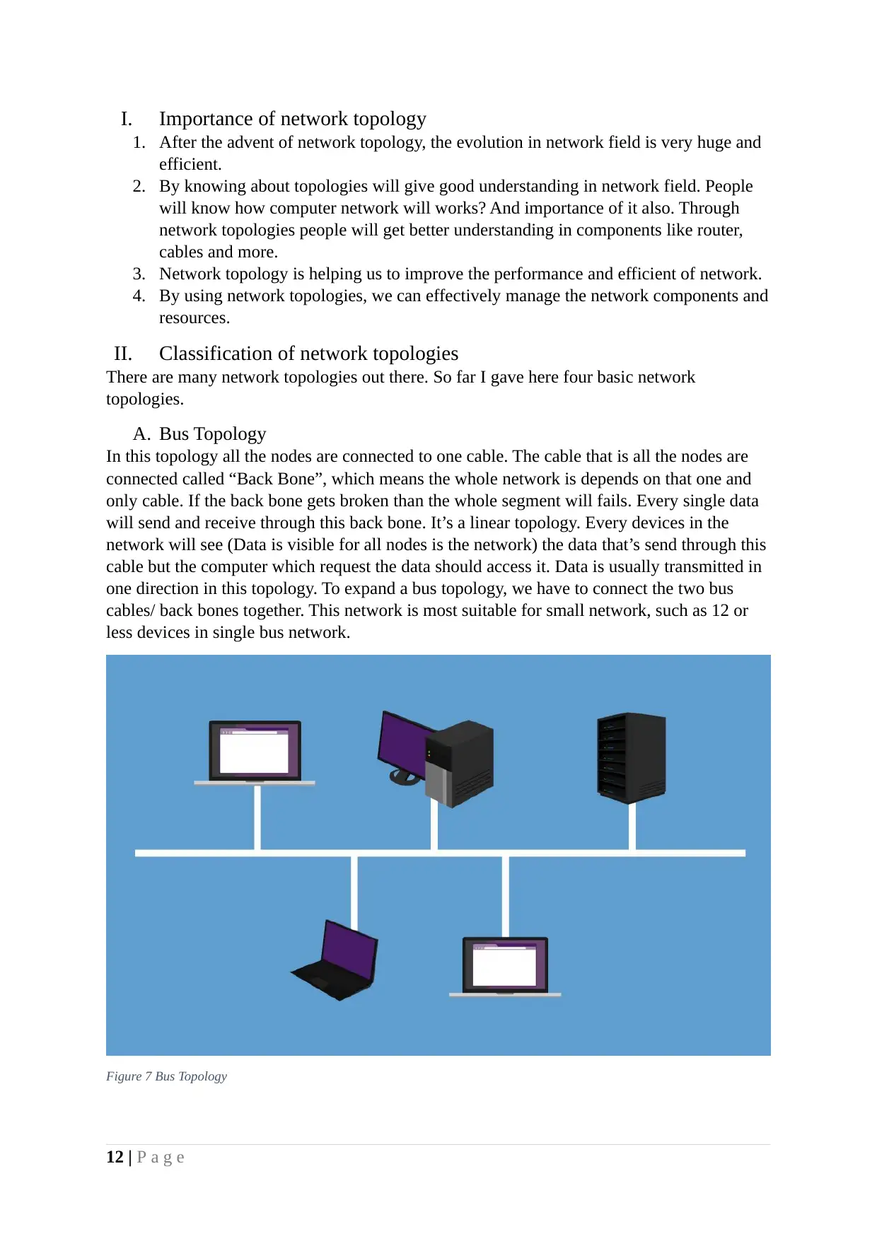
A. Bus Topology
In this topology all the nodes are connected to one cable. The cable that is all the nodes are
connected called “Back Bone”, which means the whole network is depends on that one and
only cable. If the back bone gets broken than the whole segment will fails. Every single data
will send and receive through this back bone. It’s a linear topology. Every devices in the
network will see (Data is visible for all nodes is the network) the data that’s send through this
cable but the computer which request the data should access it. Data is usually transmitted in
one direction in this topology. To expand a bus topology, we have to connect the two bus
cables/ back bones together. This network is most suitable for small network, such as 12 or
less devices in single bus network.
Figure 7 Bus Topology
12 | P a g e
1. After the advent of network topology, the evolution in network field is very huge and
efficient.
2. By knowing about topologies will give good understanding in network field. People
will know how computer network will works? And importance of it also. Through
network topologies people will get better understanding in components like router,
cables and more.
3. Network topology is helping us to improve the performance and efficient of network.
4. By using network topologies, we can effectively manage the network components and
resources.
II. Classification of network topologies
There are many network topologies out there. So far I gave here four basic network
topologies.
A. Bus Topology
In this topology all the nodes are connected to one cable. The cable that is all the nodes are
connected called “Back Bone”, which means the whole network is depends on that one and
only cable. If the back bone gets broken than the whole segment will fails. Every single data
will send and receive through this back bone. It’s a linear topology. Every devices in the
network will see (Data is visible for all nodes is the network) the data that’s send through this
cable but the computer which request the data should access it. Data is usually transmitted in
one direction in this topology. To expand a bus topology, we have to connect the two bus
cables/ back bones together. This network is most suitable for small network, such as 12 or
less devices in single bus network.
Figure 7 Bus Topology
12 | P a g e
⊘ This is a preview!⊘
Do you want full access?
Subscribe today to unlock all pages.
Trusted by 1+ million students worldwide
1 out of 40
Related Documents


Your All-in-One AI-Powered Toolkit for Academic Success.
+13062052269
info@desklib.com
Available 24*7 on WhatsApp / Email
![[object Object]](/_next/static/media/star-bottom.7253800d.svg)
Unlock your academic potential
Copyright © 2020–2026 A2Z Services. All Rights Reserved. Developed and managed by ZUCOL.